COMPUSTAR RS1B-DC3 Remote Starter Kit

WELCOME
Congratulations on the purchase of your RS1BDC3 solution. You are now a few simple steps away from enjoying your new remote starter unit with enhanced features. Before starting your installation, please ensure that your RS1B-DC3 module is programmed with the correct fi rmware for your vehicle and that you carefully review the install guide.
BOX CONTENTS
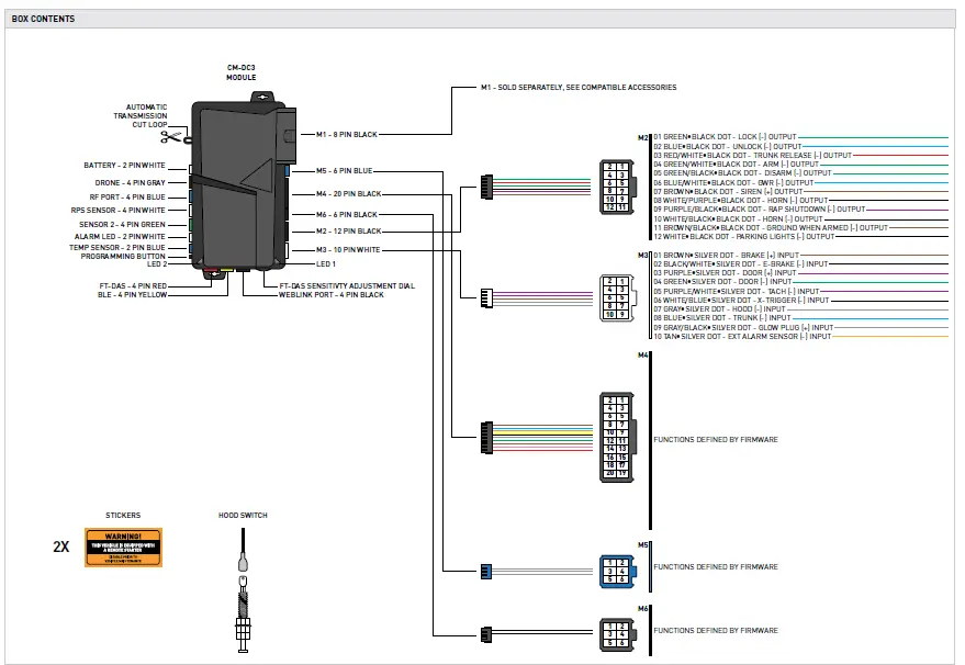
COMPUSTAR
TACH PROGRAMMING PROCEDURE
START vehicle for 15 seconds.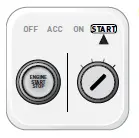
Press and hold the brake pedal.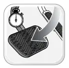
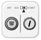
Press and release the module’s programming button. (OR if the remotes are already programmed to the vehicle, press and hold the start button of the remote for 2.5 seconds.)
Wait, LED 2 will fl ash GREEN. (See the Module Diagnostics page)
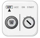
Release the brake pedal.
Module Programming Procedure completed
AFTERMARKET REMOTE PROGRAMMING PROCEDURE
- WARNING: Program aftermarket remotes before usage. A maximum of four [4x] aftermarket remotes per system

- Time restriction. Complete next step within 7 seconds

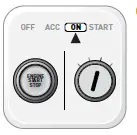
- Cycle ignition ON fi ve times [5x OFF/ON] rapidly.

- Parking Light will fl ash once [1x].

- Time restriction. Complete next step within 5 seconds from previous step.

- Press once [1x] on LOCK button of aftermarket remote.

- Parking Light will fl ash once [1x].

- To program additional remotes: repeat steps 4 to 6 using each additional remote.

- Wait, Parking Light will fl ash twice [2x].

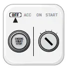
- Turn ignition to OFF position.

- Aftermarket Remote Programming Procedure completed


VALET MODE PROGRAMMING PROCEDURE
- NOTE: In Valet Mode, the Remote starter is not functional. Keyless entry, Lock and Unlock will remain functional. See RF kit user manual for alternate valet mode programming.

- Time restriction. Complete next step within 7 seconds.

- Cycle ignition ON twice [2x OFF/ON] rapidly

- Press and release the BRAKE pedal three times [3x].
- Parking Light will fl ash once [1x] then will fl ash twice [2x].

- Set ignition to OFF position

- Valet Mode Programming Procedure completed
- To exit valet mode: repeat steps 1 to 5.


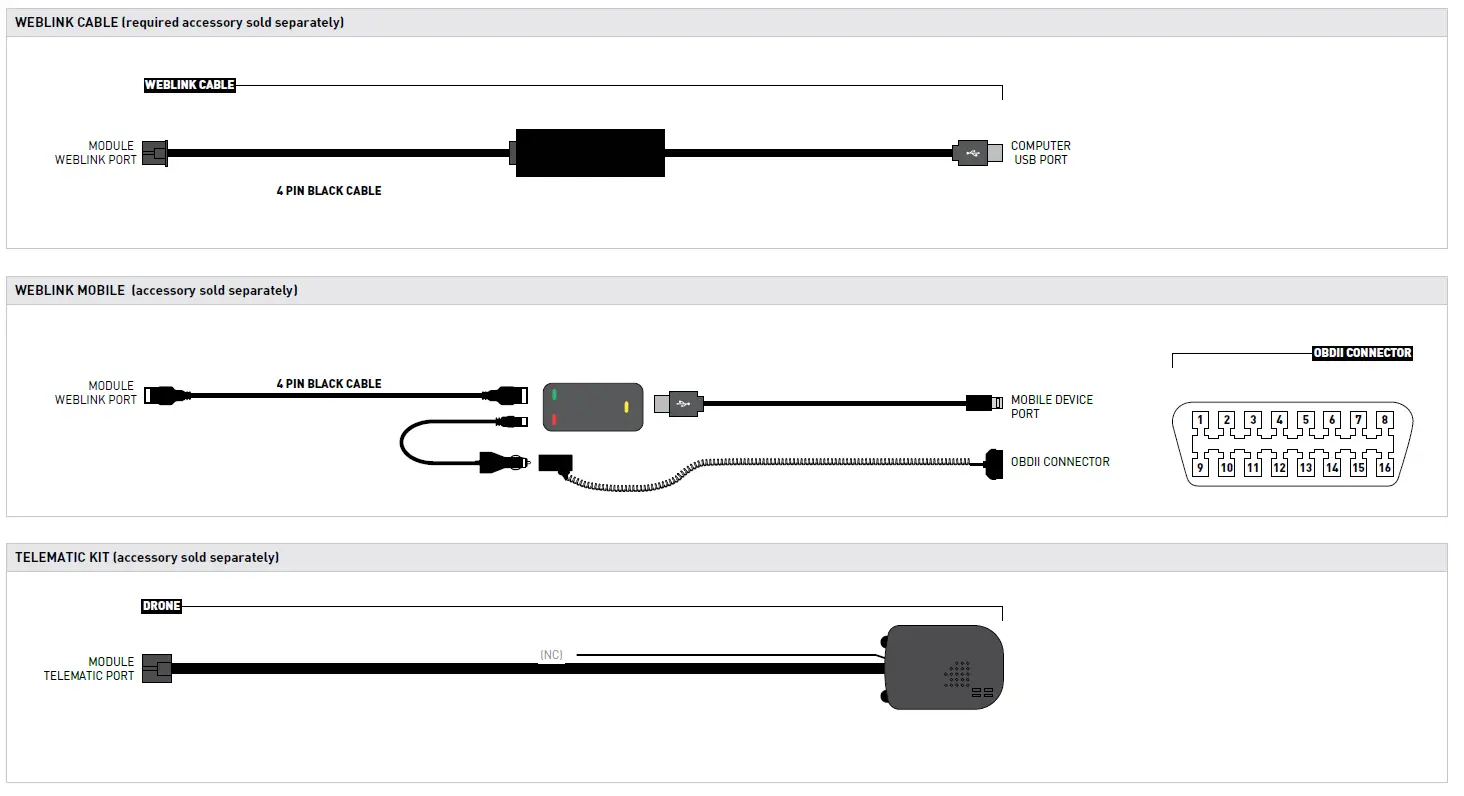
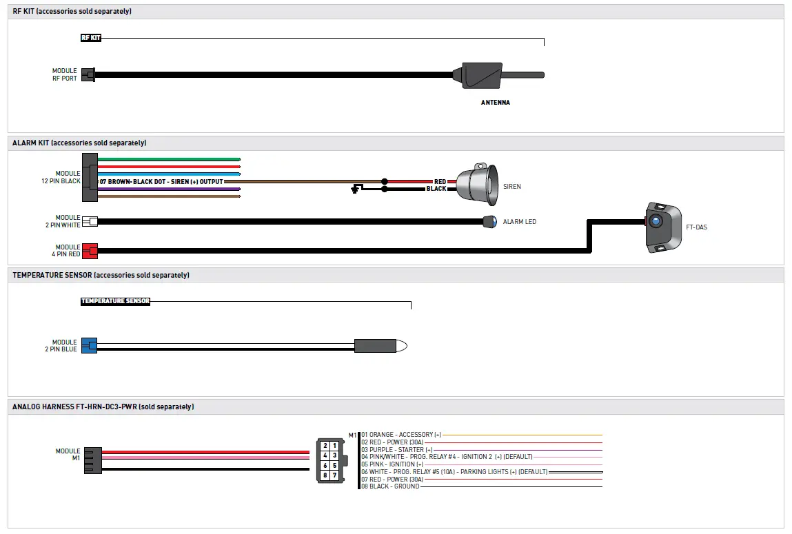
COMPATIBLE ACCESSORIES

ONLINE MODULE SETTINGS
| WEB PROGRAMMABLE MENUS | DESCRIPTION |
| MENU 1 – Remote Starter | RS related configuration options |
| MENU 2 – Doorlock Options | Convenience feature configuration options |
| MENU 3 – Security Options | Alarm activation and settings |
| MENU 4 – AUX function assignments | Set transmitter AUX buttons controls |
| MENU 5 – Programmable outputs (POC) | Set actions for programmable outputs |
| MENU 6 – Pulse Timer Output Configuration (PTO) | Set duration for pulse timer outputs (if used) |
| MENU 7 – Input Configurations | Set inputs for Auto by firmware/Data/Analog |
| MENU 8 – Output Configurations | Set outputs for Auto by firmware/Data/Analog |
MODULE DIAGNOSTICS
|
TEST MODULE | LED 1 STATUS | DIAGNOSTIC | |
|
I |
DURING MODULE PROGRAMMING | Flashing RED | Missing/wrong information from firmware or vehicle. |
| Solid RED | Module waiting for more vehicle information. | ||
| Flashing GREEN | Additional steps required to complete module programming. | ||
| Solid GREEN then OFF | Module correctly programmed. | ||
| OFF | No activity or module already programmed. | ||
|
II |
DURING TACH PROGRAMMING | 1 GREEN flash | Tach signal programmed in Analog |
| 2 GREEN flashes | Tach signal programmed in Data | ||
| 3 RED flashes | No tach signal detected | ||
| 4 RED flashes | System is in valet mode | ||
| 5 RED flashes | Tach set for ‘VTS’. No tach programming required | ||
| 6 RED flashes | Tach set for ‘assumed start’. No tach programming required | ||
|
III |
DURING REMOTE START | Flashing RED | Module incorrectly programmed. |
| Solid RED | Module incorrectly programmed. | ||
| Flashing GREEN | Module correctly programmed and operational. | ||
| Solid GREEN then OFF | Reset in progress. | ||
| OFF | Invalid ground when running status from remote starter. | ||
|
IV |
WITH IGNITION OFF | Flashing RED | Module incorrectly programmed or connected. |
| Solid RED | Module not programmed. Waiting for more vehicle information. | ||
| Flashing GREEN | False ground when running status from remote starter. | ||
| Solid GREEN then OFF | Reset in progress. | ||
| OFF | Module at rest and ready for a remote start sequence. | ||
REMOTE STARTER ERROR CODES
|
REMOTE STARTER ERROR CODES: NOTES | [X] NUMBER OF PARKING LIGHT FLASHES | DIAGNOSTIC |
| I WARNING: The following applies only when the parking lights are connected and supported by the system. II After a remote starter failure, the parking lights will flash three [3x] times, then will flash [X] number times to indicate an error code. See table. | 01 | Engine running. |
| 02 | Key in ignition at ON position. | |
| 03 | Door is open. | |
| 04 | Trunk is open. | |
| 05 | Foot brake is ON. | |
| 06 | Hood is open. | |
| 07 | The reservation is OFF. (Manual transmission only) | |
| 08 | Tach failure. | |
| 09 | The vehicle is moving (VSS). | |
| 10 | System is in Valet Mode. | |
| 11 | CAN communication failure | |
| 12 | RS not synchronized. Start vehicle with OEM key for 15 sec before trying a new RS sequence. | |
| 13 | Bypass problem. |
|
REMOTE STARTER SHUTDOWN ERROR CODES: NOTES | [Y] NUMBER OF PARKING LIGHT FLASHES | DIAGNOSTIC |
| I WARNING: The following applies only when the parking lights are connected and supported by the system. II If the engine shuts down after a remote starter sequence: Press and hold the Trunk button and the Start button at the same time for 2.5 seconds when using a 1-WAY remote. OR Press once [1x] on button “4” when using a 2-WAY remote.
The parking lights will flash four [4x] times, then will flash [Y] number times to indicate an error code. See table. | 01 | Engine tach signal is lost. |
| 02 | Emergency brake is lost. | |
| 03 | Foot brake is ON. | |
| 04 | Hood is open. | |
| 05 | Engine RPM limiter is ON. | |
| 06 | Glow plug timeout error. | |
| 07 | Vehicle is moving (VSS). | |
| 08 | N/A | |
| 09 | N/A | |
| 10 | Door is open. | |
| 11 | CAN communication failure during RS sequence. | |
| 12 | RS not synchronized. Start vehicle with OEM key for 15 sec before trying a new RS sequence. | |
| 13 | Takeover is not allowed. | |
| 14 | Shutdown error, board overheat protection. |
MODULE RESET PROCEDURE
- The following procedure resets the module programming to the vehicle. It does not reset any settings confi gured online.

- Disconnect all connectors from module except the M1 BLACK 8-pin connector and the M4 BLACK 20-pin connector

- Disconnect the M1 BLACK 8-pin connector and the M4 BLACK 20-pin connector

- PRESS AND HOLD the module’s programming button while connecting the M1 BLACK 8-pin connector and the M4 BLACK 20-pin connector.

- Wait, LED 1 will flash RED. RELEASE programming button.

- LED 1 will turn RED for 2 seconds.

- Module RESET completed

- Reconnect all connectors.

- Repeat programming procedure

- Failure to follow procedure may result with a DTC or a CHECK ENGINE error message.