![]()
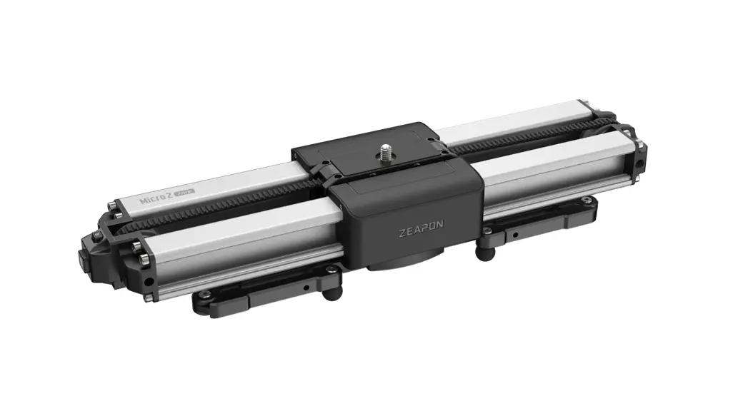
Motorized Micro2 Plus
Instructions
Please read the User Manual carefully before using Motorized Micro 2 Plus to avoid any injury or damage to the product or other property caused by operation mistake
Product Descriptions
 Safety Payload Max. Safety Payload Max.Carrying Capacity | Horizontal load C8KG |
| Other angles 4.5KG | |
 Please make sure the slide rail is unlocked before use. Please make sure the slide rail is unlocked before use. | |
 Please keep the Motorized Micro2 Plus clean and free from any obstruction. Please keep the Motorized Micro2 Plus clean and free from any obstruction. | |
For more detailed tutorial video, please visit our official website: https://www.zeapon.com
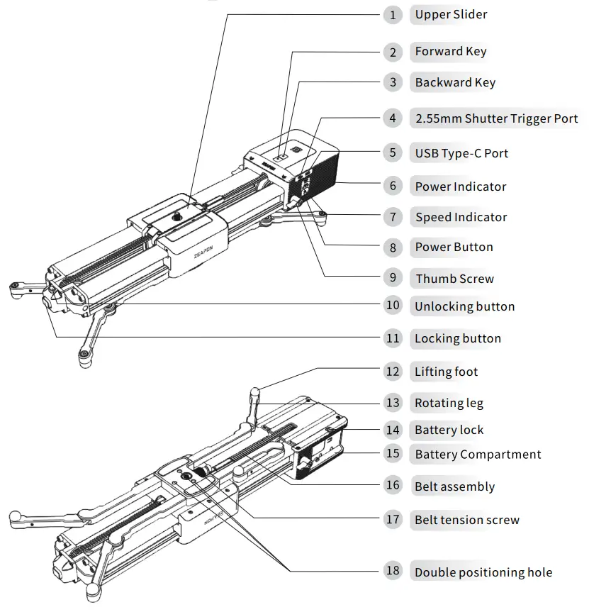
Funcation Description
| Name | Function |
| Forward Key | Slide forward |
| Backward Key | Slide backward |
| 2.5mm Shutter Trigger Port | Slider connects to camera via shutter trigger cable to control camera shutter |
| USB Type-C Port | For firmware upgrade, and charging& power supply via external PD fast charger |
| Power indicator | Green/Yellow/Red/Blue; Green: sufficient; Yellow: medium; Red: low Blue: power on |
| Speed Indicator | Three Speed Status; One light on: tow speed; Two lights on: medium speed; Three lights on: high speed |
| Power Button | Power On/Off & Function trigger |
| Thumb Screw | Fix the Slider Motor to slider |
| Battery Compartment | Compatible with F550/F750/F970 lithium battery |
| Battery lock | Used to fasten the battery to the battery compartment |
| Lifting foot | Used to adjust the height of the rail slider |
| Belt assembly | Used for the motor to drive the rail slider |
| Belt tension screw | i iced to fix inn halt and adjust tensinn of Hy) belt |
| Unlocking button | Used to unlock the rail slider |
| Locking button | Used to lock the belt and fasten the rail slider |
| Function | Key Action | Beep Sound |
| Power On | Long press Power Button for 3 seconds | / |
| Power Off | Long press Power Buttonfor 3 seconds | / |
| Forward | Long press Forward Key | / |
| Backward | Long press Backward Key | / |
| Speed Adjustment | Press Power Button once | / |
| Set Waypoints | Press Power Button twice | Set point 1: Beep sound once |
| Set point 2: Beep sound twice | ||
| DeleteAllWaypoints | Long press left+right key | Long beep sound |
| Start Running | Double presspower button | / |
| Starts/Pauses circulation | Press the Left/Right Key and Power button at the same time | Rings once |
| Automatic left and right movement | Double-click left/right buttons | / |
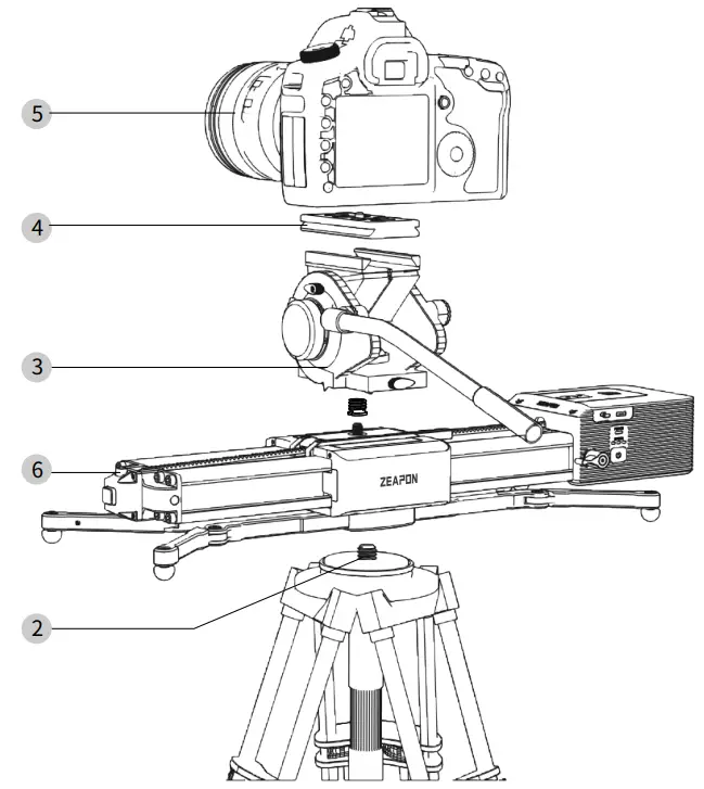
Floor Mode
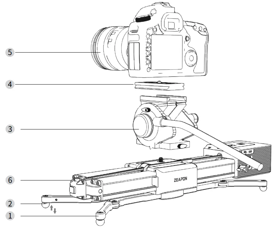
- Open the rotating legs to a proper angle.
- Adjust the supporting feet to a prope height.
- Install the fluid head on the rail slic
- Install the quick-mount plate of the fluid head to the bottom of the camera.
- Install the camera with the quick-mou plate on the rail slider.
- Press the unlocking button to opera the rail slider.
Single fluid head connection mode
- Loosen and remove the 3/8 to 1/4 screw adapter at the bottom of the rail slider.

- Fasten the 3/8 to 1/4 screw adapter removed at step 1 to the bottom of the fluid head, and rotate the fluid head to fasten it to the rail slider.
- Fasten the 3/8 to 1/4 screw adapter removed at step 1 to the bottom of the fluid head, and rotate the fluid head to fasten it to the rail slider.
- Install the quick-mount plate to the bottom of the camera.
- Installthe camera with the quick-mount plate on the fluid head.
- Press the unlocking button to operate the rail slider.
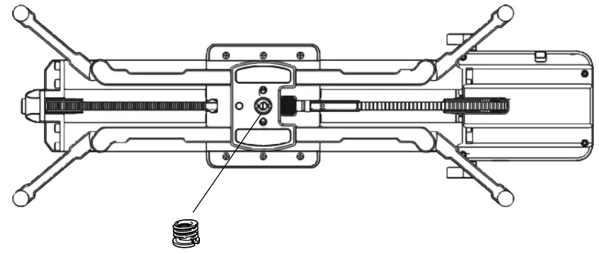
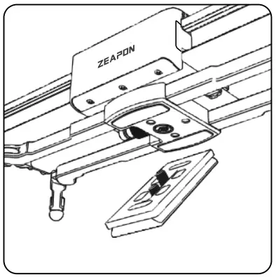
Double fluid head connection mode
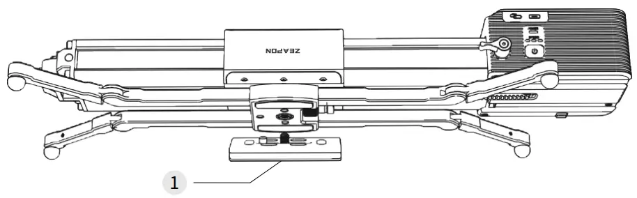
- Install the 1/4 screw in the accessory bag to a third-party quick-mount plate. Then, tighten the two positioning screws on the quick-mount plate to fix it to the bottom
ofthe rail slider.
- Install the quick-mount plate of the fluid head to the bottom of the camera.

- Screw and tighten the fluid head and the rail slider.
- Clip and fasten the rail slider installed with the fluid head to the tripod fluid head.
- Install the camera with the quick-mount plate on the fluid head.
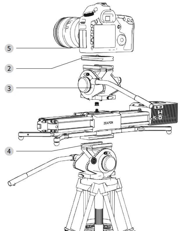
Double fluid head connection mode
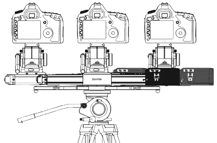
Slide the slider left and right for photographing. (as shown in the figure above)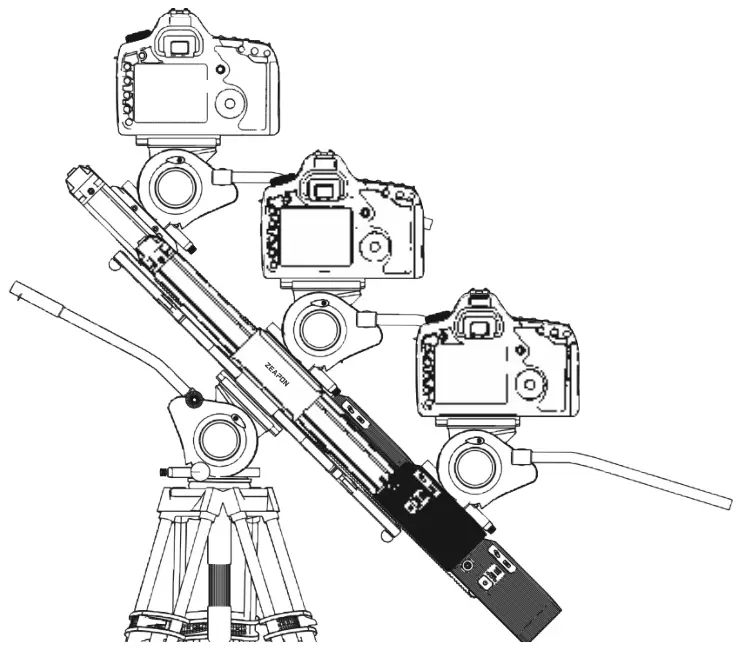 You can also move the slider left, right, upward and downward, like a JIB by changing the angle.
FCC Statement
This equipment has been tested and found to comply with the limits for a Class B digital device, pursuant to Part 15 of the FCC Rules. These limits are designed to provide reasonable protection against harmful interference in a residential installation. This equipment generates uses and can radiate radio frequency energy and, if not installed and used in accordance with the instructions, may cause harmful interference to radio communications. However, there is no guarantee that interference will not occur ina particular installation. If this equipment does cause harmful interference to radio or television reception,t which can be determined by turning the equipment off and on, the useris tencouraged to try to correct the interference by one or more of the following measures:
— Reorient or relocate the receiving antenna.
— Increase the separation between the equipment and receiver.
— Connect the equipment into an outlet on a circuit different from that to which the receiver is connected.
— Consult the dealer or an experienced radio/TV technician for help.
This device complies with part 15 of the FCC Rules. Operation is subtject to the following two conditions:(1) This device may not cause harmful interference, and (2) this device must accept any interference received, including interference that may cause undesired operation.
Changes or modifications not expressly approved by the party responsible for compliance could void the user’s authority to operate the equipment.
The device has been evaluated to meet general RF exposure requirement. The device can be used in portable exposure condition without restriction.
TIPS
Search and download “ZEAPON LAB” for Slider Motor’s App on App Store/Google Play, or on ZEAPON’s official website.
 https://www.zeapon.com/down_279.html
Please note: This product does not provide batteries and battery chargers, if necessary, please purchase separately! The data cable delivered is only for firmware upgrade!
Thanks for using ZEAPON products!
> Any unauthorized disassembling/changing of internal parts or structure may discontinue warranty service!


