Schneider SQR14102**Z Plus Switch
Features
- Wireless Z-Wave technology creates a mesh network for command and control interoperability with other Z-Wave compliant controllers and devices.
- Manual and remote ON/OFF control of any connected lighting and other electrical load.
- Programmable delayed OFF time.
- 3 configurable “power ON state”.
- Configurable child lockout feature which disables local control.
- Support single pole or 3-way (multi-location) use.
- Measure the energy usage of the connected loading, display the actual consumption (in W) and the accumulated power used (in kWh) in the user interface of the gateway.
NOTE:
- Power on state means the initial status of the device when it is powered on.
- For multi-location applications, the traditional mechanical switch or Z-Wave wireless auxiliary switch SQR50101**Z could be used along with one Z-Wave Master Switch.
- Please refer to the gateway installation manual for energy usage display and energy measurement features.
Specification of SQR14102**Z Z-Wave Plus Switch, Single Pole, Energy Monitoring Voltage 120 Vac, 60 Hz Incandescent 1000 W LED 5 A Standard ballast 1200 Va Resistive 1800 W (15 A) Motor 1/2 Hp Operating temperature 32–104°F (0–40°C) Supply connection 14 AWG 1 Wireless type Z-Wave (Support S2 and SmartStart) Wireless frequency 908.40 MHz / 908.42 MHz / 916 MHz
Precautions
CAUTION
HAZARD OF UNINTENDED USE
This device is intended to be used for non-critical automation activities. It is not intended to support life, safety, or medical equipment.
Failure to follow these instructions can result in personal injury or equipment damage.
DANGER
HAZARD OF ELECTRIC SHOCK, EXPLOSION, OR ARC FLASH
- Apply appropriate personal protective equipment (PPE) and follow safe electrical work practices. See NFPA 70E, NOM-029-STPS or CSA Z462 or local equivalent.
- This equipment must only be installed and serviced by qualified electrical personnel.
- Turn off all power supplying this equipment before working on or inside equipment.
- Always use a properly rated voltage sensing device to confirm power is off.
- Use with copper wire only.
- Indoor use only.
- Replace all devices, doors, and covers before turning on power to this equipment.
WARNING
HAZARD OF HEAT AND FIRE DAMAGE
Read all instructions before installation. The manufacturer will not be held responsible for product damage resulting from not following the instructions.
- Wet hands are strictly prohibited.
- Work strictly according to the rated load.
- Do not continue working after self-disassembly of any nature and damage of external forces.
Failure to follow these instructions can result in death, injury or equipment damage.
WARNING: This product can expose you to chemicals including Carbon black, which is known to the State of California to cause cancer, and Bisphenol A (BPA), which is known to the State of California to cause birth defects or other reproductive harm. For more information go to www.P65Warnings.ca.gov.
Notice
Wireless Range Conditions
The wireless range is the effective distance of remote control and it will be impacted by the following conditions:
- Each wall or obstacle (e.g., refrigerator, TV, etc.) between the remote or Z-Wave device and the destination device will reduce the wireless range.
- Brick, tile, or concrete walls block more of the wireless signal than walls made of wooden studs and plasterboard (drywall).
- The angle of direction between the remote or Z-Wave device and the destination device will also impact the wireless range; normally, placing the Z-Wave devices face-to-face will get the best wireless range.
- Wall-mounted Z-Wave devices installed in metal junction boxes may suffer a significant loss of range since the metal box blocks a large part of the wireless signal.
Installation
- Turn the power OFF at circuit breaker or fuse and test that power is off before wiring.
- Wire the device according to the appropriate wiring diagram.
- Check that all connections are tight and no bare wires exposed.
- Install the device into the standard outlet box using the screws provided.

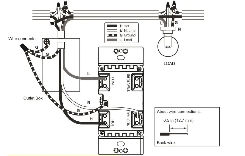
(change the CR No. to SQR14102**Z)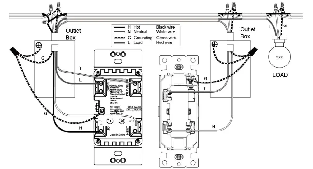
(change the CR No. to SQR14102**Z)
(Update the switch marking)
(change ‘auxiliary switch’ to ‘Mechanical Switch’)
(change the traditional switch drawing to be single-pole switch which has only 2 terminals)
(add note for wire connect to ‘Traveler’ terminal)
Note: For 3-way control along with Z-Wave auxiliary switch SQR50101**Z, there’s no wire between the Z-Wave master device and the auxiliary switch, please refer to the user manual of SQR50101**Z for the wiring diagram of the auxiliary switch itself.
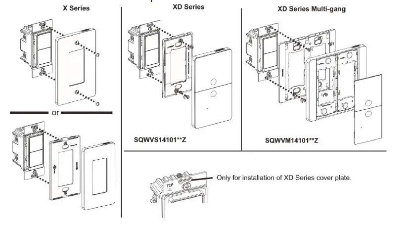
- Install the plate (not included).
- Restore power.

Operation
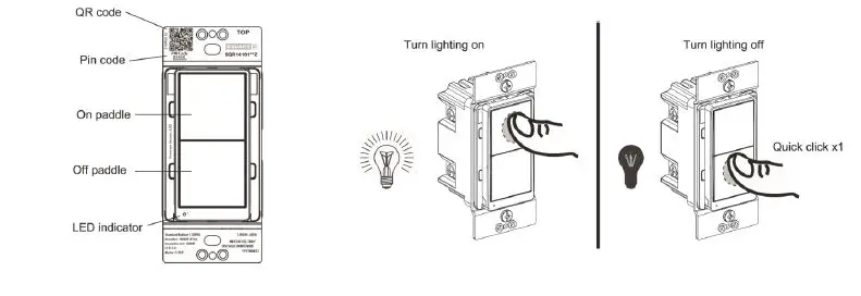
Local control:
- One short tap on upper paddle: turn on the lighting
- One short tap on lower paddle: turn off the lighting

(update the switch drawing by adding the reset button, remove unnecessary marking)
Group controls the nodes of association group 2:
Press upper and lower paddles at the same time for group on and group off.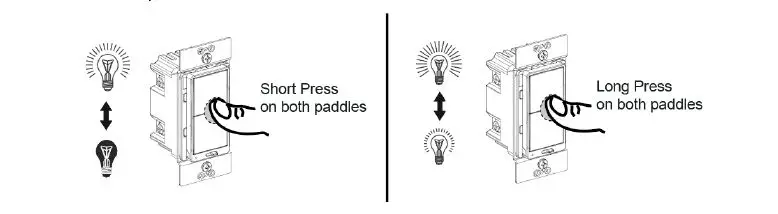
(change to switch drawing, and remove long press operation)
Way Control
| Action | Connected 3-Way Switch | |
| Traditional Mechanical Switch (wired) | SQR50101**Z Z-Wave AUX Switch (wireless) | |
| Turn on the light | Press to another state | Tap upper paddle |
| Turn off the light | Tap lower paddle | |
Inclusion to a Z-Wave network
NOTE: The device supports up to the S2-authenticated inclusion method, based on the gateway’s feature. It is highly recommended to only select S2-authenticated or the highest inclusion method, and deselect other methods. This ensures the highest security level during Z-Wave service. During S2-authenticated inclusion, users may be asked to scan the QR code or enter a 5-digit pin code attached on the device.
- SmartStart inclusion: The feature assumes the gateway has implemented SmartStart. Users could use the APP of the gateway or the gateway camera to scan the QR code on device or on device package before powering on the device, and then when the device is powered on, it shall be automatically added to the gateway.
B. Manual inclusion: When the gateway is in adding mode (please refer to the instruction of the Z-Wave gateway for the operations on gateway itself). - Exclusion from a Z-Wave network: When the gateway is in removing mode (please refer to the instruction of the Z-Wave gateway for the operations on gateway itself).

- Remote control: After the device is included in a Z-Wave gateway, the gateway can provide control of an individual device, groups of devices and scenes, and offers flexibility in setting up the lighting control network. Please refer to the gateway instructions for details.
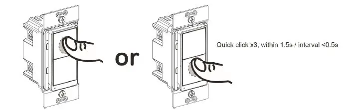
- Reset to factory defaults:
Long press the reset button for >20 seconds till the blue LED blink 5 times within one second.

NOTE:
- Use this procedure only when the Z-Wave gateway is missing or otherwise inoperable.
- Reset the device to factory default settings will set the device to not in Z-Wave network state, delete the association setting and restore the configuration setting to the default.
Advanced Setting
The advanced setting requires an advanced gateway. Basic gateway does not support this setting. Users can do the setting through the interface of the advanced gateway.
All configuration parameters can be restored to factory default settings by the gateway or by manual reset.
| Configuration | ||||||
| Parameter No. | Size | Description | Valid Value | Default Value | Unit | |
|
1 |
1 byte | Synchronization of load power and LED indicator | 0 = Power ON, LED OFF Power OFF, LED ON |
1 |
N/A | |
| 1 = Power ON, LED ON Power OFF, LED OFF | ||||||
| 2 | 1 byte | Delay Off Time | 0~240 | 0 | second | |
| 3 | 1 byte | Power On Status | 1 = Off 2 = On (full brightness) 3 = Last state | 1 | N/A | |
| 4 | 1 byte | Child Lockout | 0= Disable 1= Enable | 0 | N/A | |
| Association | ||
| Grouping ID | Max. No. of Nodes | Description |
| 1 | 5 | 1. Binary Report 2. Meter Report 3. Device Reset Locally. |
| 2 | 5 | Basic Set |
LED Indication
|
Blue LED flashing | LED blinks slowly (once per 3 seconds) for 3 minutes: device not in network LED stays on for 1 minute: device in the network
LED blinks once per second: adding/leaving network LED blinks 5 times within one second: signal for releasing the reset button LED blinks 4 times within 2 seconds: start to perform reset process LED blinks quickly (twice per second) for 5 seconds: device receive OTA command or OTA fail |
| Blue LED on | Device is turned on (default setting, can be configured) |
| Blue LED off | Device is turned off (default setting, can be configured) |
Trouble Shooting
| Issue | Solution |
| SmartStart inclusion taking too long | Power cycle the device to escalate the inclusion. |
| Inclusion is unsuccessful | Move the gateway closer to the device and repeat the inclusion operation. |
FCC Compliance Statement
Federal Communication Commission Interference Statement
The equipment has been tested and found to comply with the limits for a class B Digital Device, pursuant to part 15 of the FCC Rules. These limits are designed to provide reasonable protection against harmful interference in a residential installation. This equipment uses, generates and can radiate radio frequency energy and, if not installed and used in accordance with the instruction, may cause harmful interference to radio communication. However, there is no guarantee that interference will not occur in a particular installation. If this equipment does cause harmful interference to radio or television reception, which can be determined by turning the equipment off and on, the user is encouraged to try to correct the interference by one or more of the following measures:
- Reorient or relocate the receiving antenna.
- Increase the separation between the equipment and receiver.
- Connect the equipment into an outlet on a circuit different from that to which the receiver is connected.
- Consult the dealer or an experienced radio/TV technician for help.
FCC Radiation Exposure Statement:
This equipment complies with FCC radiation exposure limits set forth for an uncontrolled environment. This equipment should be installed and operated with minimum distance 20cm between the radiator & your body.
RF Exposure: A distance of 20 cm shall be maintained between the antenna and users, and the transmitter module may not be co-located with any other transmitter or antenna.
Non-modification Statement:
Any changes or modifications not expressly approved by the party responsible for compliance could void the user’s authority to operate this equipment.
FCC Supplier’s Declaration of Conformity
Product Name: Z-Wave Plus Switch
Model Number: SQR14102WHZ, SQR14102LAZ, SQR14102BKZ
Suppliers Name: Schneider ElectricSuppliers Address (USA): 800 Federal Street Andover, MA 01810 USA
Suppliers Website: www.se.com/us
FCC Compliance Statement
This device complies with part 15 of the FCC Rules. Operation is subject to the following two conditions: (1) This device may not cause harmful interference, and (2) this device must accept any interference received, including interference that may cause undesired operation.
ISED Statement
This Class [B] digital apparatus complies with Canadian CAN ICES-003(B)/NMB-003(B).. This device contains licence-exempt transmitter(s)/receiver(s) that comply with Innovation, Science and Economic Development Canada’s licence-exempt RSS(s). Operation is subject to the following two conditions:
- This device may not cause interference.
- This device must accept any interference, including interference that may cause undesired operation of the device.
L’émetteur/récepteur exempt de licence contenu dans le présent appareil est conforme aux CNR d’Innovation, Sciences et Développement économique Canada applicables aux appareils radio exempts de licence. L’exploitation est autorisée aux deux conditions suivantes :
- L’appareil ne doit pas produire de brouillage;
- L’appareil doit accepter tout brouillage radioélectrique subi, même si le brouillage est susceptible d’en compromettre le fonctionnement.
This equipment complies with ISED RSS-102 radiation exposure limits set forth for an uncontrolled environment. This equipment should be installed and operated with a minimum distance of 20cm between the radiator and any part of your body. Pour se conformer aux exigences de conformité CNR 102 RF exposition, une distance de séparation d’au moins 20 cm doit être maintenue entre l’antenne de cet appareil ettoutes les personnes.
Model number: SQR14102WHZ, SQR14102LAZ, SQR14102BKZ
Warranty Information
Schneider Electric warranties its products to be free of defects in materials and workmanship for a period of two (2) years. There are no obligations or liabilities on the part of Schneider Electric for consequential damages arising out of or in connection with the use or performance of this product or other indirect damages with respect to loss of property, revenue, or profit, or cost of removal, installation, or reinstallation.

 Manual")

 Manual")


