Bove Technology B9 VW Ultrasonic Water Meter
Product Information
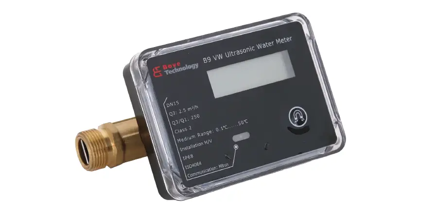
The B9 VW Ultrasonic Water Meter is a high-precision water flow monitoring device designed for residential and commercial applications. It utilizes ultrasonic technology to accurately measure the water flow rate and volume. The meter is equipped with a compact and durable body, making it easy to install in tight spaces. The meter has a digital display that shows the water flow rate and volume in real-time. It is compatible with various pipe sizes and can be used with both hot and cold water.
Product Features
- Ultrasonic technology for accurate measurements
- Digital display for real-time monitoring
- Compact and durable design
- Compatible with various pipe sizes
- Can be used with hot and cold water
Specifications
- Model: B9 VW
- Body material: Brass
- Pipe size compatibility: DN15-DN50
- Measurement range: 0.03-12m³/h
- Measurement accuracy: ±1.5%
- Working temperature: 0-40℃
- Working pressure: ≤1.6MPa
- Display: Digital LCD
- Power supply: DC3.6V, Lithium battery
- Battery life: ≥6 years
Product Usage
Before installing the B9 VW Ultrasonic Water Meter, please read the Installation & User Guide carefully to ensure proper installation and usage. The following steps are provided as a general guideline:
- Turn off the main water supply and drain the pipes to prevent water flow during installation.
- Select an appropriate location for the meter installation based on the pipe size and compatibility.
- Connect the meter to the pipe using appropriate fittings and ensure a tight seal.
- Turn on the main water supply and check for any leaks or irregularities in the water flow.
- The digital display will show the water flow rate and volume in real-time.
- Monitor the water flow rate and volume regularly to ensure efficient usage and identify any abnormalities.
If you have any questions or encounter any issues during installation or usage, please contact BOVE TECHNOLOGY for assistance.
Thank you for choosing our products
- The contents of this manual are subject to change without prior notice as a result of continuing improvements to the meter’s performance and functions.
- Every effort has been made in the preparation of this manual to ensure the accuracy of its contents. However, should you have any questions or find any errors, please contact BOVE TECHNOLOGY.
- Copying or reproducing all or any part of the contents of this manual without the permission of BOVE TECHNOLOGY is strictly prohibited.
Bove Intelligent Technology Co., Ltd
Add: Level 5, Building 5, No. 36,
Changsheng South Road, Jiaxing, Zhejiang, China, 314000
Tel: +86 573 83525916
Fax: +86 573 83525912
Email: [email protected]
www.bovetech.com
General Information
Please note that the following installation conditions must be obeyed:
Pressure Requirement: MAP16.
Environmental Class: E1, M1
Installation requirement: There must be a distance of minimum 25 cm between signal cables and other installations
If medium temperature is below 10°C or above 90°C in flow sensor, It’s recommended that the calculator be wall-mounted.
Note: Seal or any safety marks on the meter must not be damaged or removed, and doing so will void the warranty and calibration of the meter.
Technical Specification
Flow Sensor
The flow sensor is a device used to measure the velocity of flow by using the principle of ultrasound. It can measure the average velocity along the path of an emitted beam of ultrasound by averaging the difference in measured transit time between the pulses of ultrasound propagating into and against the direction of the flow. The flow measurement is based on an acoustic wave time of flight principle. The flow meter body is equipped with 2 ultrasonic transducers facing 2 acoustic reflectors.
Flow sensor data:
| Manufacturer | Bove | ||||
| Type | B9VW | ||||
| Accuracy class | Class2 | ||||
| MAP | 16bar | ||||
| Max Pressure loss at Q3 | ≤40kPa | ||||
| Max admissible temperature | 50°C | ||||
| Limits of temperature (Θmin and Θmax) | 0.1-30°C,0.1-50°C | ||||
| Installation requirements | Min.10*DNlengthofstraightpipebeforethemeter, andMin.5*DNlengthofstraightpipeafterthemeter (DNisthediameterofmeter) | ||||
| Basic mounting orientation and other specified orientations | Horizontal/Vertical | ||||
| Output signal for testing | Analogsignal1Mhz | ||||
| power supply | LithiumBattery | ||||
| Current used | Average20uA,Peak4mA | ||||
| Climatic and mechanical class | B
|
Calculator
The calculator is a device that calculates the flow volume consumed based on signals from flow sensor. It’s also the control, display and data store part for the meter.
Calculator data:
| Manufacturer | Bove |
| Climatic and mechanical class | B |
| Electromagnetic Class | E1 |
| Mechanical Class | M1 |
| Display unit | m3,L |
| Battery power supply requirements | Seepart:4Powersupply |
| Pulse input device class | N/A |
| Max permissible flow sensor signal(Pulse rate) | N/A |
| Output signal for normal operation | M-Bus,Infrared,RS485 |
| Pulse output device class | N/A |
| Output signal for testing | M-Bus,Infrared,RS485 |
| Liquid if other than water | N/A |
Completer meter
| Manufacturer | Bove | ||||||||
| Flow Measurement | |||||||||
| Type | DN (mm) | Flow Rate (m3/h) | Dimensions (mm) | Connection | |||||
| Q1 | Q2 | Q3 | Q4 | Length | Width | Height | ――― | ||
| B9VW-15 | 15 | 0.01 | 0.016 | 2.5 | 3.125 | 165 | 75 | 89 | G3/4″ |
| B9VW-20 | 20 | 0.016 | 0.0256 | 4 | 5.0 | 195 | 75 | 94 | G1′ |
| B9VW-25 | 25 | 0.025 | 0.04 | 6.3 | 7.875 | 225 | 75 | 104 | G11/4″ |
| B9VW-32 | 32 | 0.04 | 0.064 | 10 | 12.5 | 180 | 75 | 114 | G11/2″ |
| B9VW-40 | 40 | 0.064 | 0.1 | 16 | 20 | 200 | 75 | 119 | G2′ |
| Pressure Loss △P | ≤40KPa | ||||||||
| MAP | 1.6MPa | ||||||||
| Water temperature range | 0.1to30°C,0.1to50°C | ||||||||
| Q3/ Q1 | 160/250/400 | ||||||||
| Accuracy | Class2 |
| Maximum permissible error in upper flow rates range Q2 £ Q £ Q4 | ±2%(atΘ≤30°C) ±3%(atΘ>30°C) |
| Maximum permissible error in lower flow rates range Q1 £ Q < Q2 | ±5% |
| Scale interval(m3) | 0.001 |
| Capacity of calculator | 99999,999 |
| Type of liquid | Water |
| Installation requirements | Min.10*DNlengthofstraightpipebeforethemeter,and Min.5*DNlengthofstraightpipeafterthemeter(DNis thediameterofmeter) |
| Basic mounting orientation and other specified orientations | Horizontal/Vertical |
| Display & Indication | |
| Display unit options | m3,L |
| Display LCD | 8-digit |
| Volume | 0.001m³ |
| Time to LCD off | 3min. |
| Environmental Requirement | |
| Environmental Class | E1,M1 |
| Ambient temperature | 5~55°C(Indoorandnon-condensing) |
| Storage temperature | -20~60°C |
| Protection Class | IP68 |
| Data history | 24month |
| Power Supply | |
| Battery | Lith3.neO6ViumBattery |
| Battery Life | ≥6Years |
| 24V DC | Externalsupplyforspecialversion(Optional) |
| Mechanical Specification | |
| Top cover | ABS |
| Bottom cover | ABS |
| Flow Body | MS58 |
| Flow Pipe | PPS |
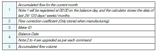
Data Storage
Installation
Requirements for installation environment
B9 VW series ultrasonic water meter has been designed for indoor installation in non-condensing environments with ambient temperatures from 5~55°C.
The meter must not be under any mechanical stress when installed in the pipe.
The meter must be protected against pressure shocks in the pipe.
Protection class IP68 allows long-term submergence, provided that all cable unions have been correctly mounted and that the plastic cover has been properly fastened.
All control cables must be drawn separately and not parallel to e.g. power cables or other cables with the risk of inducing electromagnetic interference. There must be a distance of min. 25cm between signal cables and other installations.
If two or more meters are to be installed shall be in parallel, the axis-center distance between two meters shall be at least 135mm minimum.
Before Installation
Prior to installation of the flow sensor, the pipe shall be thoroughly flushed out, and any dirty, stone alike items must be removed from the pipe. Cavitation in the system must be avoided. If a risk of frost exists, empty the system and, if necessary, remove the meter. If the water is soiled, fit the strainer in the pipe before the meter.
Mounting of Flow Sensor
Consider the dimensions of the water meter, and the distance with surroundings, minimum 3 cm free space.
Straight sections of 10×DN before and 5×DN after the meter are recommended, to homogenize the temperatures of water.
The meter is to be installed so that the direction of the arrow on the meter housing corresponds to the direction of flow. Avoid the collection of air bubbles in the meter during the installation process.
The connecting pipe at the two ends must be on the same horizontal level. Install horizontally only, not tilted, inclined or overhead. Install the flow sensor into horizontal or up streaming pipelines.
Do not install at highest point of piping to avoid air inside the flow sensor. The flow sensor must NOT be installed in the positions where swirling flow exists (swirling flow is normally caused by bending pipe), or pulsatile flow exists (pulsatile flow is normally caused by pump, therefore the flow sensor must be installed as far as possible from pump and must not be installed on the outlet of pump) or air may build up.
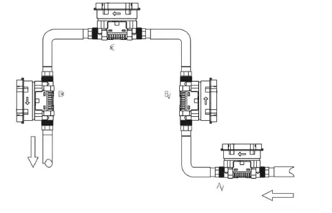
- Recommended flow sensor position
- Recommended flow sensor position
- Unacceptable flow sensor position
- Unacceptable flow sensor position in open system, acceptable in closed system.
Mounting Step
- Step 1: Flush the piping system thoroughly before mounting the meter.
- Step 2: Sufficient distance.10×DN straight pipe in upstream and 5×DN straight pipe in downstream. (DN: Diameter)
- Step 3: The specific seal gasket and connector only supplied by Bove Technology.
- Step 4: On the two sides of the meter, there should be one filter (if the water is soiled) and two shut-off valves.
- Step 5: After finishing the above operations, seal the meter only if the sealing has not been done before delivery from factory.
Installation of non-return value
The meter can be supplied with a non-return valve (if required) on request. The non-return valve must be installed on the water inlet end of meter when installing.
After the installation
The tightness must be proved by pressurizing with cold water, slowly filling the pipe on completion of the installation.
Open the shut-off valves carefully and check installation for leakage. While the piping system is operating, check whether the volume display correctly and the temperatures display corresponding with the actual temperatures (see the display information).
When the response thresholds are exceeded and the flow rate is positive, the volume is summated.
Make the segment test, in order to displays all display segments for test purposes.
The operating hours are counted from initial connection of the battery. The date is incremented daily. As a standard the meter is delivered with the local time, or destination time if required.
Power supply
B9 VW Series can be fitted with one ER18505 and ER26500 with operating time of 6/10/15 years respectively.
| Brand | EVE |
| Type | LithiumBattery |
| Model No. | ER18505/ER26500 |
| Rated capacity | 4000mAh/9000mAh |
| Rated voltage | 3.6V |
| Max recommended continuous operating current | 130mA |
| Max pulse current | 180mA |
| Reference weight | 28g |
| Max dimension | 18.7×50.5mm |
| Operating temperature | -60°C ~ +85°C |
Interface & Communication
IrDA
B9 VW Series are all equipped with an optical interface IrDA to IEC62056-21 as a standard. In addition, one of the following options can be ordered for remote output.
M-BUS
- Cable: connected with galvanic isolation
- Voltage: 50V max.
- Current: M-Bus loads
Addressing: primary or secondary
Note: A higher frequency is not allowed and may result in meter malfunction!
Data transmission in the compatibility mode (= standard, one data frame) or in the full mode (3 data frames) possible.
If the meter is equipped with “M-Bus”, it is delivered with a two wire cable, which can be lengthened with a cable 2 x 0.75mm2 (put a distributing box). Pay attention to the proper polarity in case of the pulse output. If the meter is read out via M-bus, the allowed mean frequency of reading must not be exceeded. Any more reading is not allowed and may result in a damage to meter.
The M-Bus or pulse variant of the meter is supplied with a 2-wire cable with wire end ferrules.
| Version/Color | Pulse | M-Bus (2-wire) |
| Red | Pulse | M-Bus |
| Black | GND | M-Bus |
Pulse Output (Optional)
- Pulse output for heat or volume, with 0.6m cable connected, with galvanic isolation Pulse significance: 1 pulse per 100 liter
- Pulse length: 100 ms (Programmable)
- Heat / Volume: specify in order or change with service-software
- Voltage: max. 30 V
- Current: max. 30 mA
- Pulse break: min. 25ms
- Classification OC (acc. to EN 1434-2)
- Voltage drop: ca. 1.3V at 20 mA
RS-485(Optional)
- Cable: connected with four-core cable
- Voltage: 5-24V.
| Version/Color | RS-485 |
| Red | VCC |
| Black | GND |
| Yelow | A |
| Green | B |
Sigfox (Optional)
| RCZ Serial | RCZ1 | RCZ2/4 |
| EIRP/dBm (max) | 16 | 24 |
| Data transmission | Configurable | |
LoRaWAN (Optional)
| ISM Band | EU433 | EU868 | IN865 | US915 |
| Class | ClassA | |||
| Network Access Mode | OTAAorABP | |||
| Transmitting Power | 12.15 dBm(max) | 16 dBm(max) | 20 dBm(max) | 20 dBm(max) |
| Data transmission | Each6hasdefault | |||
| LTE Band | B3 | B5 | B8 | B20 | B28 |
| Data transmission | Each12h | ||||
| Operator | 2G(GPRS) |
| Data transmission | 24h |
Operation & Display
B9 VW Series is fitted with an easily readable LCD, including 8 digits, measuring units and information field.
The display automatically returns to LCD sleep mode 3 minutes after the latest activation of the push button. When power on, the meter will reset and displays full screen to allow users to detect if there is any problem with the LCD.
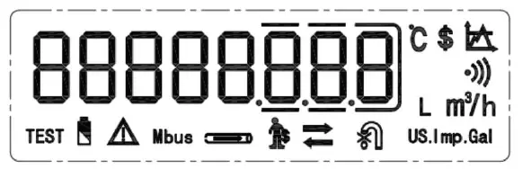
Fig. LCD Display
| No. | Icon | Name | Meaning |
| 1 | Calibration mode | Under calibration | |
| 2 | Low battery warming | User is reminded to replace the battery with a new one. | |
| 3 | Error warning | Warnings for error | |
| 4 | Communication type | Mbus communication | |
| 5 | Pipe state | Blink means enpty pipe |
| 6 | Credit alarm | Prepaid mode only | |
| 7 | Button indication | Button detected once appear | |
| 8 | Reverse flow | Revers eflow | |
| 9 | Valve indicate | Valve control meter only | |
| 10 | Unit | Gal Unit | |
| 11 | Unit | Volume and flow rate | |
| 12 | Wireless communication | Reserve | |
| 13 | Unit | Temperature | |
| 14 | Currency | Prepaid mode only | |
| 15 | Tariff | Prepaid mode only |
Users may touching off the button by magnet to read the meter information such as accumulated volume, current flow rate, etc.
To save the battery, the meter switches to sleep mode (display off) if the button is not pressed for approx. 3 minutes. It can be woken up by trigger the button approximately 2 seconds. The following information is displayed in order by short pressing the button: accumulated flow, instant flow, date, time, accumulated working time, Meter ID, address, meter type, software version No., checksum, etc.
Menu List (User Loop)
Touching off the button for more than 2 seconds and holding it on will bring up the four menus for users to select.
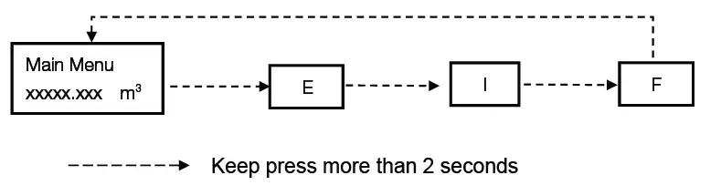
Main Menu
Shortly touching off the button to display items under the Main Menu one by one in the following order to check the measurement data:
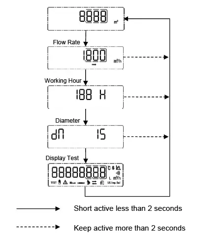
Menu E
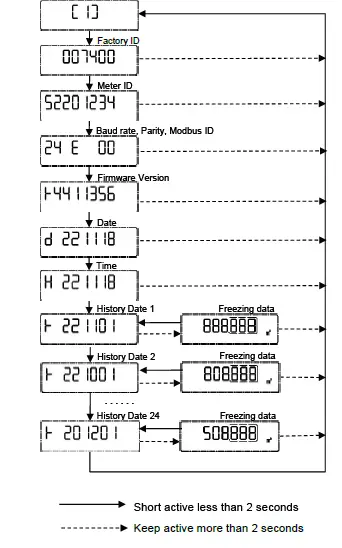
Touching off the button for less than 2 seconds to display items under Menu E one by one in the following order to check the meter information: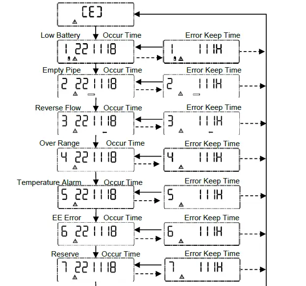
Menu I
This Menu shows history date records of last 24 logs. Touching off the button for more than 2 seconds to select the log, then flow consumption will be displayed in turn.
Menu F
The following diagram shows Menu F (Calibration mode only). In F mode, Accumulated flow value is able to reset automatically, when flow is zero and starts to exceed the preset value then the current accumulated value is clear to zero. Also the value can be reset by long-trigger the button (over 2 seconds). The meter exit the calibration mode if no operation for 2 hours.
Note: preset value is pre-set to make sure zero calculation when there’s no water flow in the pipe, usually the value equals to 0.1% of Q3.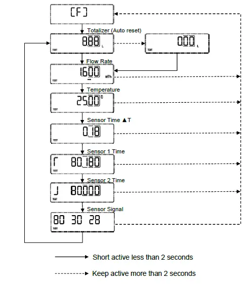
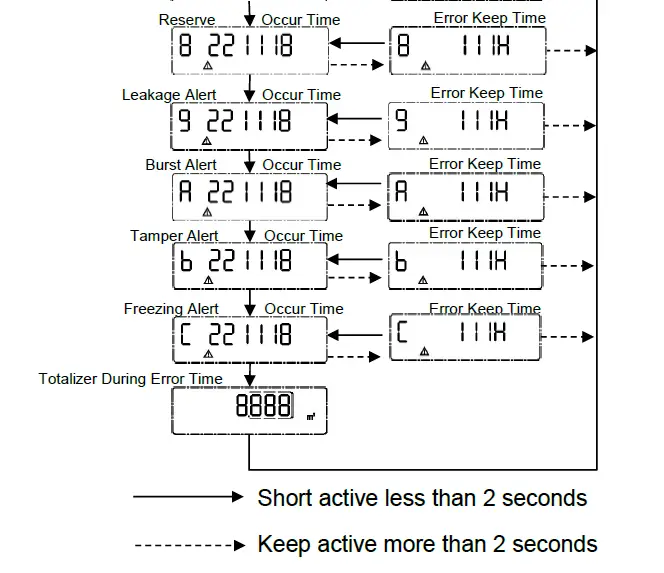
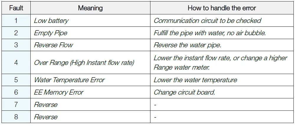
Error and Warning
The meter constantly performs self-diagnosis and can display various faults. Visual indication on the LCD display in the event of an warning. Permanent visual indication on the LCD:
Corporate Profile
Bove provides comprehensive solutions on flow metering and control to over 30 countries in the globe. We design and manufacture range of flow metering solutions and IoT (internet of things) consumer products, which includes high accuracy water meter, thermal energy meter, testing bench, smart communication software’s for residential, commercial and industrial sectors. Since 2009 Bove has always been moving on the edge of technology to deliver state of the art products and solutions to customers all around the world.
A couple of our engineers are dedicated in metering and Communication industry for over 10 years, core team are previously working in Huawei, Baidu, IBM, and CitiGroup, etc. With these talents Bove are able to provide prompt services and reliable products to our global customers.
Bove is committed to address the unique challenges that the residential and industry are facing, including increasing customer demand, water scarcity, and environment conservation. With hope, honor and our hard and quality work, we are looking to future to make Bove one of the best brands in metering industry in the world.
Our Mission
To exceed our customers expectation by providing prompt, quality and reliable technology.
Our Vision
Creating an Eco Society
Bove can accept no responsibility for possible errors in catalogues, brochures and other printed material. Bove reserves the right to alter its products without notice. This also applies to products already on order provided that such alterations can be made without sub sequential changes being necessary in specifications already agreed. All trademarks in this material are property of the respective companies. Bove and the Bove logotype are trademarks of Bove Technology. All rights reserved.
Copyright© 2023 Bove Intelligent Technology Co., Ltd


