
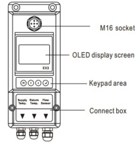
![]() E-ST Ultrasonic Flowmeter
E-ST Ultrasonic Flowmeter
User Manual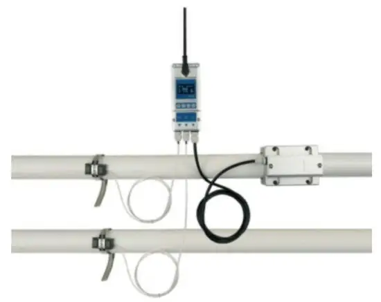
Notice Thank you for choosing Model E-ST
This instruction manual contains the important use and operation information of the flow meter. Please read carefully the reference manual before the operation to make your flow meter exert the best performance.
If you make a mistake there will be affected the meter’s working and reduce the meter’s life or cause some malfunctions.
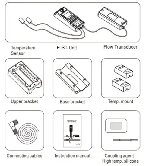
Product component
Inspection should be made before installing the Flow meter. Check to see if the spare parts are in accordance with the packing list. Make sure that there is no potential damage to the enclosure due to a loose screw or loose wire, which occurred during transportation.
Any questions, please contact your representative as soon as possible.
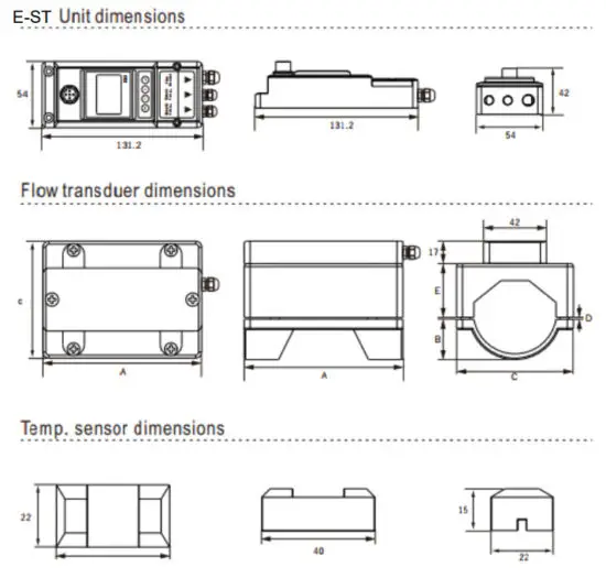
Dimensions
| Model | A (mm) | B (ma’) | C (mm) | D(mm) | |
| min | max | ||||
| DN15 | 25 | 10 | 58 | 1/018 | 7.5/022.3 |
| DN20 | 25 | 15 | 58 | 1/025 | 4/028 |
| DN 25 | 29. | 19. | 58 | 1/032 | 4/035 |
| DN 32 | 30. | 24 | 68 | 1/038 | 9/045 |
| DN40 | 36 | 27 | 78 | 1/048 | 7/054 |
| DN 50 | 41 | 32 | 91 | 1/5/1958 | 8/5/1964 |
| DN 65 | 47. | 40 | 105 | 1/065 | 7/074 |
| DN80 | 52. | 43 | 119 | 1/076 | 13/086 |
Installation and connect
E-ST needs to install the flow sensor and temperature sensor and clean the pipeline before Installation.
Make sure no dirt, paint, or other stains on the surface of the tube. Then put the bottom parts on the side of the pipe.
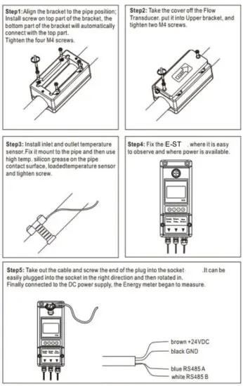 When ‘E-ST is installed, the Energy meter is wired.
Connect the DC power and RS485 output.
Panel function
Powering on
As soon as the E-ST Energy meter is switched on, the self-diagnosis program will start to run.
Signal Quality (SQ value)
- value is short for Signal Quality. It indicates the level of the signal detected.
- value is indicated by numbers from 0-99 represents the minimum signal detected while 99 represent the maximum.
Normally, the transducer position should be adjusted repeatedly and the coupling compound should be checked frequently until the signal quality detected is as strong as possible.
Keypad Functions
Follow these guidelines when using the Flow meter keypad:

![]() Setting or display mode, when it is setting mode, that can return to the previous menu,
Setting or display mode, when it is setting mode, that can return to the previous menu, ![]() and
and![]() scroll up and down to select the menu, when press
scroll up and down to select the menu, when press ![]() move to next digit, press()and the numbers scroll from 0 to 9, you can select the number. Press
move to next digit, press()and the numbers scroll from 0 to 9, you can select the number. Press![]() to confirm.
to confirm.
Window descriptions
Display Menu
- When the power on, the meter will display Velocity/Net Totalize.
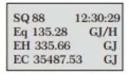
 Display signal quality (SQ), time, heat power ( Eq) heat totalizer (EH), cold totalizer (EC)
 - Press
 will display T1, T2, delta T, and press
  will return to the previous menu.
 Display date, time, outlet temp. (T1), inlet temp.(T2), Delta temp. (DT)
 - Press will display Eq, EH, press will return to the previous menu.
 Display signal quality (SQ), time, Heat power (GJIh), Heat totalizer (EH)
 - Press will display Eq, EC, and press will return to the previous menu.

- Press will display Flow rate, Net totalizer, press will return to the previous menu.
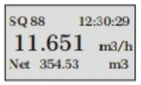
 Display signal quality (SQ), time, flow rate, Net totalizer
 - Press· will display the Unit runtime, press will return to the previous menu.
 Display Unit runtime, monthly heat totalizer (E HM), monthly energy totalizer (ECM), monthly flow totalizer (ETM)
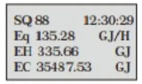 Display signal quality (SQ), time, heat power ( Eq) heat totalizer (EH), cold totalizer (EC)
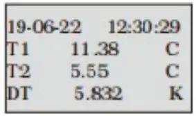 Display date, time, outlet temp. (T1), inlet temp.(T2), Delta temp. (DT)
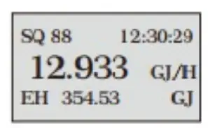 Display signal quality (SQ), time, Heat power (GJIh), Heat totalizer (EH)
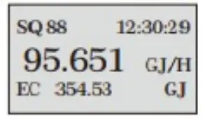
 Display signal quality (SQ), time, flow rate, Net totalizer
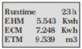 Display Unit runtime, monthly heat totalizer (E HM), monthly energy totalizer (ECM), monthly flow totalizer (ETM)
Setup menu
Press![]() will display Setup menu.
will display Setup menu.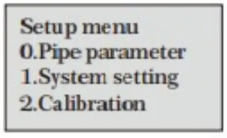
The following options are available (by ![]() or
or ![]() buttons)
buttons)
| 0. Pipe parameter | 3. Output setting |
| 1. System setting | 4. Energy setting |
| 2. Calibration | 5. History Data |
Setup Menu – pipe parameter
Press)
Select![]() .Pipe parameter, then
.Pipe parameter, then ![]() display:
display:

The following options are available (by ![]() ·or
·or![]() buttons)
buttons)
0. Outer diameter
1. Wall thickness
2. Material: Move ·![]() or
or ![]() ·can option PVC, Carbon steel, Steel, Copper pipe.
·can option PVC, Carbon steel, Steel, Copper pipe.
3. Fluid type: Move ![]() or
or ![]() an option Water, Sea Water, Oil…etc.
an option Water, Sea Water, Oil…etc.
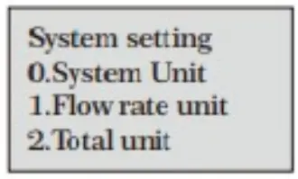
Setup Menu – System setting
Press![]() , Select 1. System setting, then
, Select 1. System setting, then ![]() display:
display:
The following options are available (by(·)or(· buttons)
0. System unit: Move![]() or
or![]() an option Metric, English.
an option Metric, English.
1. Flow rate unit: Move![]() or
or![]() can option m3Ih, LPM, GPM.
can option m3Ih, LPM, GPM.
2. Total unit: Move·![]() or·can m3, L, GAL.
or·can m3, L, GAL.
3. Totalize RESET: AII parameters are reset, Press![]() , move,
, move, ![]() or
or![]() arrow to select “YES” or “NO After “YES is selected.
arrow to select “YES” or “NO After “YES is selected.
Time set
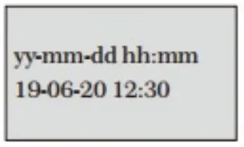
Generally, it is unnecessary to modify the date-time as the system is provided with a highly reliable perpetual calendar chip.
System lock
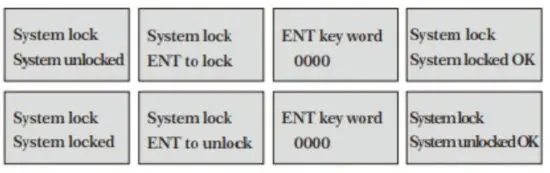
Once the system is locked, any modifications to the system are prohibited, but the parameter is readable. “Unlock” using your designated password. The password is composed of 1to 4 numbers.
System INFO
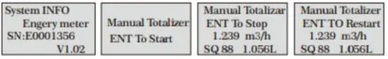
System INFO: Display the serial number (SN) of the meter. This SN is the only one assigned to each flow meter ready to leave the factory.
The factory uses it for file setup and for management by the user. Set zero: Press![]() ; reset Zero Point” which was set by the user.
; reset Zero Point” which was set by the user.
Manual Totalizer: The manual totalize is a separate totalize. Press ![]() to start, and press
to start, and press ![]() to stop it. It is used for flow measurement and calculation.
to stop it. It is used for flow measurement and calculation.
Display dir

Can choose the direction of the display, convenient to observe the measurement data.
Setup Calibration
Press![]() .Select 2. Calibration, and then
.Select 2. Calibration, and then![]() display:
display:
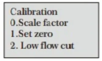
0. Scale factor
Refers to the ratio between “actual value” and reading value”. For example, when the measurement Is 2.00, and It Is Indicated at 1.98 on the instrument, the scale factor reading is 2/1.98. This means that the best scale factor constant is1.01.
- Set zero: Press
 ; reset ‘Zero Point which was set by the user.
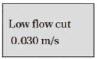
- Low flow cut: The flow rate falls below the low flow cutoff value.
 The flow indication is driven to zero. This function can prevent the flow meter from reading flow after a pump as shut down but there is still liquid movement in the pipe, which will result in a totalization error.
Generally, 0.03m/s is recommended to enter as the low flow cutoff point.
The low flow cutoff value has no relation to the measurement results once the velocity increases over the low flow cutoff value. - Manual zero


 The flow indication is driven to zero. This function can prevent the flow meter from reading flow after a pump as shut down but there is still liquid movement in the pipe, which will result in a totalization error.
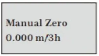
The seldom-used calibration method is suitable for experienced operators to artificially input an offset superimposed on the measured value
in order to obtain the true value when other calibration methods cannot be used well.
For example:
Actual measured value =250 m3/h
The offset valve =10 m3lh
Meter display =240 m3/h
In general, this value should be set: to “0”.
Setup Menu – Output
Press![]() .Select 3. Output setting, and then
.Select 3. Output setting, and then ![]() display:
display:
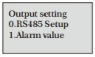
0. RS485 setup
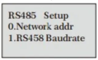
The window is used to set the serial port. It connects with the equipment of its serja! port set of parameters must match.
Move![]() or
or![]() can option baud rate: 2400, 4800, 9600, 19200.
can option baud rate: 2400, 4800, 9600, 19200.
Data length fixed: 8; Stop bit for 1.
Factory serial port parameters for the default “9600, 8, None, 1.
- Alarm value(Option)


Enter the low alarm value; any of the measured flow, which is lower than the low value, will activate the alarm in the OCT hardware or relay output signal.
Enter the high alarm value; any of the measured flow, which is higher than the high value, will activate the alarm in the OCT hardware or relay output signal.
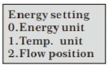
Setup Menu – Energy setting
Press![]() , Select 4. Energy Setting, and then
, Select 4. Energy Setting, and then ![]() display:
display:
The following options are available (by· ![]() or
or![]() buttons)
buttons)
0. Energy unit: Move![]() or
or![]() an option: GJ, MBtu, KWh, MWh.
an option: GJ, MBtu, KWh, MWh.
- Temp unit: Move or an option: C or F
- Flow position: Move (·or·can option: Inlet, Outlet
- DT sensitivity: Move or, You can change the value
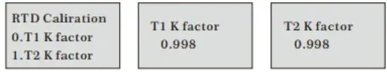
- RTD Calib: Temperature sensor calibration

Setup Menu – History Data
Press![]() . Select 5. History Data, and then
. Select 5. History Data, and then![]() display:
display:
0. By Day
Display: Daily heat totalizer (EHD), Daily cold totalizer(ECD), Daily Flow totalizer (ETD)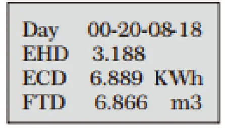
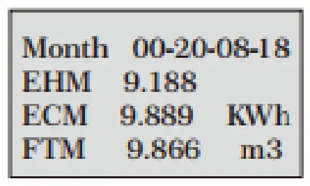
- By Month
Display: Monthly heat totalizer(EHM), Monthkt cold totalizer(ECM), Monthly Flow totalizer (ETM)
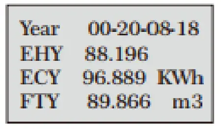
- By Year
Display: Year heat totalizer (EHM), Year cold totalizer(ECM), Year Flow totalizer (ETM)
![]() Denmark
Denmark
KL I NGER
Danmark A/ S
Nyager 1 2- 1 4
DK- 2605
www.kling


