EVERSPRING AD370 MOS Dimmer Module
General Introduction
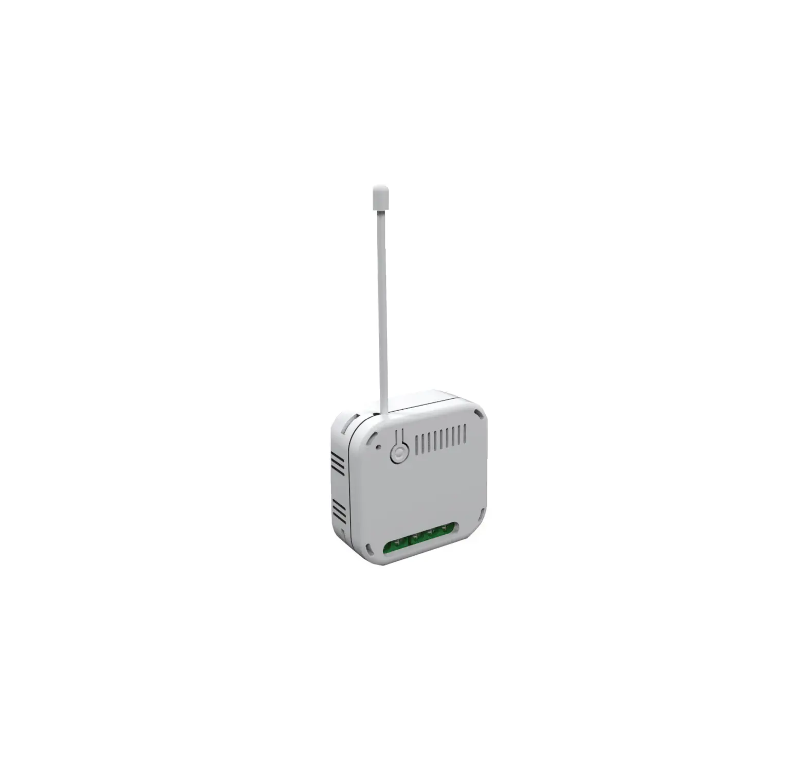
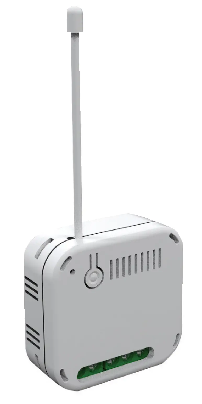
AD370 is an inwall dimmer module to dim lighting appliances by Z-WaveTM wireless control. It uses MOS technology to achieve both Trailing-edge dimming for LED lighting and Leading-edge dimming for older lamps. Compact in design, yet certified for safety makes it suitable for installation in crammed electrical box located behind wall switches. This product can be operated in any Z-Wave network with other Z-Wave certified devices from other manufacturers. All mains operated nodes within the network will act as repeaters regardless of vendor to increase reliability of the network.
Main Features
- Latest Z-Wave 700 series
- MOS technology for Trailing/Leading edge phase dimming
- Suitable for 3-wire and 2-wire (no neutral) connections
- Self -detect whether 3-wire or 2-wire installation
- Installer friendly; no need for loopback cable when 2-wire (Patent-pending)
- Usable dimming range set through Auto Calibration
- Overload and overheat protection
- Integrated scheduler controller
- Power consumption reporting
- Auto-detect load type: resistive, inductive, capacitive
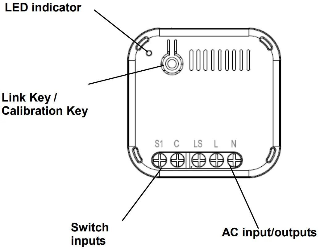
Product Overview
Compatibility table
Supported loads are listed below. Before installation the load connected, do not exceed the limits below.
| Load Type | Maximum Load(@230V) | Suitable Operation Mode |
| Resistive load | 276W | Trailing Edge |
| Incandescent load | 200W | Trailing Edge |
| Dimmable LED | 10W~200W, if 2-Wire 2W~200W, if 3-Wire | Trailing Edge |
| ELV halogen lamps and dimmable LED bulbs with Electronic transformers | 10W~200W | Trailing Edge |
| MLV halogen lamps with Ferromagnetic transformers | 10W~200W | Leading Edge * |
| Non-dimmable LED | Max 60W (3-Wire only) | On/off mode, no dimming function |
*Attention: Forcing this to Trailing edge may result in damage to the load or the dimmer module
Installation
Safety Precautions
To ensure your safety, please read this manual carefully before installing the device; follow the instructions exactly. The manufacturer shall not be legally responsible for any equipment damage or personal injury caused by incorrect installation or operation other than that covered in the manual.
IMPORTANT
- Avoid installing the unit in storming or raining weather.
- Installation must be performed by skilled technicians who are informed about the standards and technical requirements of the appliance and its proper installation. Note that the In-WallOn/Off Module is designed to be installed in a wall switch box to operate
- Check your local codes as they apply to your situation. If the house wiring is of aluminum, consult with an electrician about proper wiring methods.
- Before proceeding with the installation, turn off the power to the lighting circuit at the circuit breaker or fuse box to avoid electrical shock.
- Do not connect the device to loads exceeding the recommended values. Connect the device exactly as shown in the provided diagrams. Improper wiring may be dangerous and result in equipment damage.
- Be sure to isolate or switch off power source before installing or maintenance.
- Do ensure that the power supply circuit is protected by a 16 amp circuit breaker or suitable equivalent fuse.
- Electronic switch is designed to operate in electrical home installation. Faulty connection or use may result in fire or electric shock.
- Do not connect different types of light sources simultaneously.
- Do not connect the power supply without a load.
Connecting the Wires
WARNING : BEFORE INSTALLATION, TURN OFF AC POWER BY TURNING OFF CIRCUIT BREAKER.
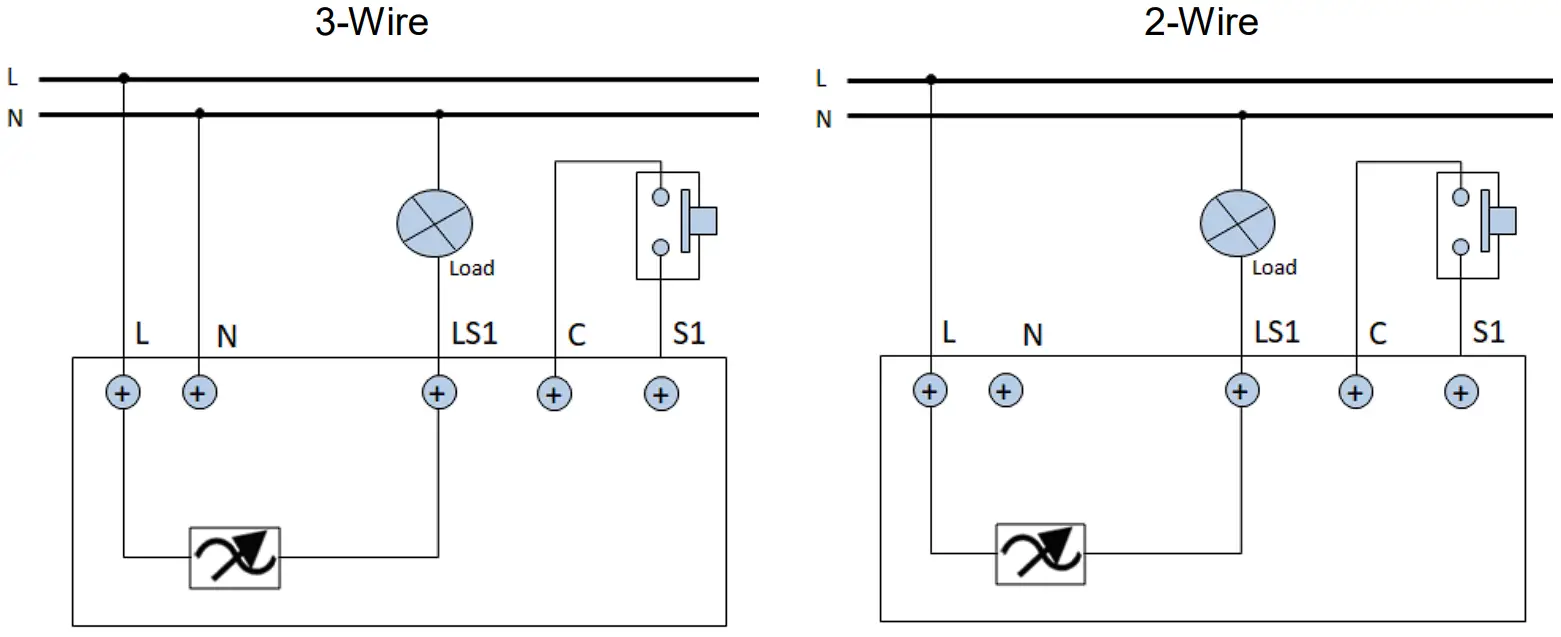
- Connect the wires from electrical wall box to the module, the module supports either 2-wire or 3-wire connections. Refer to the wiring diagram below to wire accordingly.

Note: Unlike other solutions in the market, wiring AD370 for 2-wire connection does not need a loopback cable between output and N terminal. The module‟s patented technology inside will self-detect which wiring configuration was used.
Warning: S1 is meant for external switches only. Never connect any form of load to S1, which may cause electrical hazard and damage. Circuit must be protected by a fuse or MCB rated current not exceeding 16 A - Once wiring is complete, turn back on the mains power. Do not seal the module inside the wall box yet.
- When first powered on, the module will attempt some calibration with the lamp.
User may notice dimming and perhaps flickering during this period.
– For Calibration status/results, refer to the LED indicator table below
– Calibration can also be cancelled or started anytime using the Link key.
LED Indicator
Table below shows the LED indicator and operation for
| Status | Operation | LED Indicator |
| Calibration | Link key: Press over 2 seconds | Orange LED blinking |
| Calibration cancel | Link key: Press once | Orange LED stop blinking |
| Calibration finish | Green LED flash 3 times, means lamp is Dimmable. See “a. Dimming Control” | |
| Red LED flash 3 times means lamp is Non-dimmable. See „b. On/Off Control”. | ||
| a. Dimming control | Switch at S1: Press and hold Switch at S1: Double click to set to Maximum or Minimum level. | Dimming: Green |
| b. On/Off control | Switch at S1: Short press | ON: Green LED ON OFF: LED OFF |
| Not added to Z-Wave network | Red LED 2-second on, 2-second off |
Adding to Z-Wave Network
The unit supports SmartStart function, where inclusion is initiated automatically on power on, and repeated at dynamic intervals for as long as the device is not included into a Z-Wave network. The Z-Wave Controller must support SmartStart for this to work. SmartStart enabled products can be added into a Z-Wave network by scanning the Z-Wave QR Code present on the product with a controller providing SmartStart inclusion. No further action is required and the SmartStart product will be added automatically within 10 minutes of being switched on in the network vicinity.
If the Controller does not support SmartStart function, follow the steps for manual Inclusion
- Put the Z-Wave Controller into Inclusion mode.
- Press the link key or external switch three times within 1.5 seconds to put the unit into inclusion mode.
Note: If the Z-Wave Controller utilizes S2 security protocol, you may be asked to enter a 5 digit Device Specific Key (DSK) .This can be found in one of two places: on the QR code label on the back of the unit on the insert card inside the packaging - Once calibration and Z-Wave setup is complete, tuck the module inside the wall box and seal it.
Calibration
For dimmable electronic lamps such as LEDs, the range of brightness adjustment available to the user varies greatly across different manufacturers, lamp wattage and complicated further by method of connection whether it‟s 3-wire or 2-wire (sometimes called non-neutral). Adding to the confusion, sometimes even LEDs sold as non-dimmable lamp can be dimmed.
The figure below compares dimming range between two connection methods for the same lamp.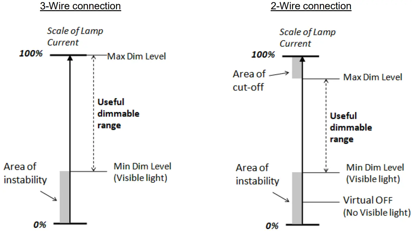
The calibration feature of AD370 attempts to simplify this by setting automatically, for every lamp, the useful dimmable range without negative effects seen by the user. To do so, it will detect the load type and then apply the appropriate control method, trailing edge or leading edge, when adjusting brightness.
The calibration is initiated when,
– module is powered on,
– user press and hold the Link key on the module for more than 2 secs,
– command sent from Controller
Detail results of the calibration will be reported though Controller, see Z-Wave Configuration settings in
Programming section. Calibration outcome is also indicated on the module‟s LED; Green for load is dimmable, Red for non-dimmable load, defaulting to a simple on/off operation only.
Following the Calibration, user can still modify the settings to fine tune if needed.
Operation
Dimming
Dimming is operated by external switch connected to S1. Press and hold the switch and the dimmer will increase/decrease the brightness of the lamp. Release the switch at desired brightness.
Max/Min
Using the switch connected to S1, activating the switch quickly two times will set to Maximum brightness and repeating again will set brightness to Minimum.
Metering:
Power measurement is reported in Watts at periodic intervals set through the Controller. It can report any sudden change power consumption when exceed a set threshold.
Note: In 2-wire connection, the voltage setting in Parameter 13 needs to be set correctly to report proper power consumption value.
Save and restores the last status after a power failure:
The unit can be set to remember the last brightness level before AC power is cut off (such as power black-out). When AC is restored, the unit will return to the last level automatically.
Overload protection:
If the software detects the maximum power is exceeded for more than 30 seconds, the dimmer will turn off to protect the load. An over-current notification will be sent to the Controller.
Over-temperature protection:
If the internal temperature of dimmer exceed 80℃, the dimmer will turn off automatically. A “System emergency shutoff” notification will be sent to the Controller.
Programming
Z-Wave PlusTM Info
| Role Type | Node Type | Installer Icon | User Icon |
| Slave Always On | Z-Wave Plus node | Light Dimmer Switch Device Type | Light Dimmer Switch Device Type |
Version
| Protocol Library | 0x03 (Slave_Enhance_232_Library) |
| Protocol Version | 7.10 (SDK 7.16.03) |
Manufacturer
| Manufacturer ID | Product Type | Product ID |
| 0x0060 | 0x0033 | 0x0001 |
AGI (Association Group Information) Table
| Group | Profile | Command Class & Command (List) N bytes | Group Name(UTF-8) |
| 1 | General | Notification Report, Device Reset Locally Notification Switch Multilevel Report Meter Report Configuration Report Indicator Report Application Rejected | Lifeline |
| 2 | Control (0x2001) | Basic Set | On/Off control |
| 3 | Control (0x2002) | Switch Multilevel Start/Stop | Switch Multilevel Start/Stop |
| Action | Report to Group | Command |
| Reset | 1 | Device Reset Locally Notification |
| First time power on | 1 | Notification Report |
| Overload | 1 | Notification Report |
| Hardware Fail | 1 | Notification Report |
| Over temperature | 1 | Notification Report |
| Dimming value change | 1 | Switch Multilevel Report |
| Wattage auto report | 1 | Meter Report |
| Calibrate start/end report | 1 | Configuration Report |
Association Command Class
| Group | Max Node |
| 3 | 5 |
Switch Multilevel command
| Value |
| 0x00: Off 0x01~0x63: 1~99% 0XFF: the last dimmer level |
| Duration |
| 0x00: Instantly 0x01~0x7F: 1~127 seconds 0x80~0XFE: 1~127 minutes 0xFF: Factory default duration 0XFE: Unknown |
Metering command
| Meter Type | Scale | Size | Precision |
| Electric meter | kWh(0) | 2 | 1 |
| W (2) | 2 | 1 | |
| V (4) | 2 | 0 | |
| A (5) | 2 | 3 |
Notification
| Event | Type | Event | Event Parameters Length |
| Power applied for first time | 0x08 | 0x01 | 0x00 |
| Over load detected | 0x08 | 0x08 | 0x00 |
| System hardware failure | 0x09 | 0x01 | 0x00 |
| System emergency shutoff | 0x09 | 0x07 | 0x00 |
Z-Wave Configuration settings
The configurable values are as following:
| Par. No. | Parameter Function | Size | Range | Default | |
| 1 | Switch Type | 2 | 0: Momentary | 1: Toggle | 0 |
| 2 | Auto-on time | 2 | 0~32767 (sec.) | 0 (not auto-on) | |
| 3 | Auto-off time | 2 | 0~32767 (sec.) | 0 (not auto-off) | |
| 4 | Remember last status | 2 | 0:do not remember , | 1: remember | 1 |
| 5 | Interval for wattage/kWh auto report | 2 | 60~32767 (sec.) | 600 sec. | |
| 6 | Report when exceed % change of wattage | 2 | 10~100 (%) | 25% | |
| 7 | Maximum dimming value | 2 | 1~100 (%) | 100% | |
| 8 | Minimum dimming value | 2 | 1~100 (%) | 10% | |
| 9 | MOS operation mode | 2 | 0: Disabled, (unknown load) 1: On/off only, no dimming | 2: Trailing edge dimming 3: Leading edge dimming | 2 |
| 10 | Calibration Mode | 2 | 0:IDLE , | 1: Calibrate | 0 |
| 11 | Auto Calibration | 2 | 0: not calibrate automatically 1: Calibrate after first power on when module is excluded | 2: Calibrate after first power on when module is included; 3: Calibrate after first power on | 1 |
| 12 | Dimming speed | 2 | 1~600 (sec.) | 4 sec. | |
| 13 | Set voltage when in 2-wire | 2 | 1~500 (V) | 230V | |
| 14 | Use external switch for Inclusion and Exclusion | 2 | 0:Disable | 1:Enable | 1 |
| 15 | Lamp type detected | 2 | 0:Unknown 1: Lamp recognized as non dimmable | 2: Lamp recognized as dimmable | Read only |
| 16 | Wire connection type | 2 | 0: Unknown 2: 2-Wire | 1: Unknown 3: 3-Wire | Read only |
| 17 | Power auto report threshold | 2 | 0~300 (W) | 0: Disable | |
| 18 | Dimming curve | 2 | 0: Linear | 1: Logarithmic | 0 |
| 19 | Load type detected | 2 | 0: Unknown 1: resistive load | 2: capacitive load 3: inductive load | Read only |
Command Classes
| Command Class | Version | Required Security Class |
| ZWAVEPLUS_INFO | 2 | None |
| ASSOCIATION | 2 | Highest granted Security Class |
| MULTI_CHANNEL_ASSOCIATION | 3 | Highest granted Security Class |
| ASSOCIATION_GRP_INFO | 3 | Highest granted Security Class |
| TRANSPORT_SERVICE | 2 | None |
| VERSION | 3 | Highest granted Security Class |
| MANUFACTURER_SPECIFIC | 2 | Highest granted Security Class |
| DEVICE_RESET_LOCALLY | 1 | Highest granted Security Class |
| INDICATOR | 3 | Highest granted Security Class |
| POWERLEVEL | 1 | Highest granted Security Class |
| SECURITY | 1 | None |
| SECURITY 2 | 1 | None |
| SUPERVISION | 1 | None |
| FIRMWARE_UPDATE_MD_ | 5 | Highest granted Security Class |
| NOTIFICATION | 8 | Highest granted Security Class |
| SWITCH_ MULTILEVEL | 4 | Highest granted Security Class |
| METER | 5 | Highest granted Security Class |
| CONFIGURATION | 4 | Highest granted Security Class |
| APPLICATION STATUS | 1 | None |
Additional Command Classes Supported
- Indicator: To manipulate indicator resources in a supporting node. An indicator may be an LED.
- Firmware Update: For OTA function.
Troubleshooting
Table below lists typical problems encountered:
| Symptom | Cause of Failure | Recommendation |
| Device not responding and LED not displaying | Wiring to AC mains may be incorrect | Check if wiring is correct, or voltage is too high or too low |
| Cannot turn on/off the lamp, | The connected load has | Turn on the switch at the load |
| but LED indicator is normal | its own on/off switch | |
| Cannot control by Z-Wave but switch control works. | Lost wireless connection with Controller |
|
Manual Inclusion/Exclusion
The table below lists the several steps involved when adding or removing the unit from the Z-Wave network.
| Action/Status | Description | Red LED indication |
| No node ID(0x50) | The Z-Wave Controller does not allocate a node ID to the unit. | 2-second on, 2-second off |
| Inclusion | 1. Put the Z-Wave Controller into inclusion mode. | |
| 2. Press the link key or external switch three times within 1.5 seconds to put the unit into inclusion mode. | ||
| Exclusion | 1. Put the Z-Wave Controller into exclusion mode. | |
| 2. Press the link key or external switch three times within 1.5 seconds to put the unit into exclusion mode. | ||
| Reset (This procedure should only be used when the network primary controller is inoperable.) | 1. Press the link key or external switch three times within 1.5 seconds to put the unit into exclusion mode. | |
| 2. Within 1 second of step 1, press link key or external switch again and hold until LED is off (about 5 seconds). | ||
| 3. Node ID is excluded. The device reverts to factory default state and will be in auto-inclusion mode for 4 minutes. | ||
| Failed or successful results can be viewed on the Z-Wave Controller. | ||
Note: If you are connecting this unit to a Z-Wave Controller that utilizes the S2 security protocol, you may be asked to enter a 5 digit Device Specific Key (DSK) that is unique to each unit by your controller. This can be found in one of two places:
– on the QR code label on the back of the unit
– on the insert card inside the packaging
Specifications
| Frequency Range | EU: 868.42MHz |
| Power Input | AC230V,50Hz |
| Maximum Power Load(AC230V) | Resistive load: 276W Incandescent load: 200W Dimmable LED: 10W~200W (2-Wire); 2W~200W (3-Wire) Dimmable electronic transformer for 12V ELV halogen lamps and dimmable bulbs: 10W~200W Ferromagnetic transformers for 12V operated MLV halogen lamps: 10W~200W Non-dimmable LED(support on/off): 60W (3-Wire) |
| Transmission Range | 100 meters (Indoor open area with antenna outside of wall box ) |
| Working Temperature | 0°C – 40°C |
*Specifications are subject to change without notice
Warning:
Do not dispose of electrical appliances as unsorted municipal waste. Please use separate collection facilities instead.
Contact your local government for information regarding the available collection systems.
If electrical appliances are disposed of in landfills or dumps, hazardous substances can leak into the groundwater and get in to the food chain, damaging your health and well-being.
When replacing old appliances, the retailer is legally obligated to take back your old appliances for disposal free of charge.
www.everspring.com
3F., No. 50, Sec 1, Zhonghua Rd., Tucheng Dist.,
New Taipei City 23666, R.O.C