iROBOT i1 Robot Vacuum
Safety Information
 | Please read the following safety information carefully before operating the machine. Information includes important safety information about installation, usage, and maintenance. Pay attention to all warning labels and instructions in this manual and printed on the machine. |
If you have questions about how to operate the machine safely, please contact your local Antari dealer for help.
- Keep this device dry.
- Always connect to a grounded circuit to avoid risk of electrocution.
- Before connecting the machine to power, always check the voltaged indicate on the machine matches to your local AC voltage. Do not use the machine if ACpower voltage does not match.
- Disconnect the machine from AC power before servicing and when not in use.
- If the supply cord is damaged, contact your local Antari dealer for replacement.
- This product is for indoor use only! Do not expose to rain or moisture. If fluid isspilled, disconnect AC power and clean with a damp cloth. If fluid is spilled onto electronic parts, immediately unplug the machine and contact your local Antari dealer for advice.
- No user serviceable and modifiable parts inside. Never try to repair this product, an unauthorized technician may lead the machine to damage or malfunction.
- For adult use only. Children being supervised not to play with the machine. Never leave the machine running unattended.
- The machine is not to be used by persons (including children) with reduced physical, sensory or mental capabilities, or lack of experience and knowledge.
- Installed in a well ventilated area. Provide at least 50 cm space around the machine.
- Never add flammable liquid of any kind to the machine.
- Make sure there are no flammable materials close to the machine while operating.
- Only use Antari fluid. Other fluid may lead to heater clog and malfunction.
- If the machine fails to work, unplug the machine and stop operation immediately.
- Contact your local Antari dealer for .
- Before transporting the machine, make sure the fluid tank is completely drained.
- Smoke fluid may present health risks if swallowed. Do not drink smoke fluid. Store it securely. In case of eye contact or if fluid is swallowed immediately look for medical advice.
Unpacking and Inspection
Immediately upon receiving the machine, carefully unpack the carton, check all content to ensure that all parts are present and have been received in good condition. If any parts appear damaged or mishandled from shipping, notify the shipper immediately and retain the packing material for inspection
What is included:
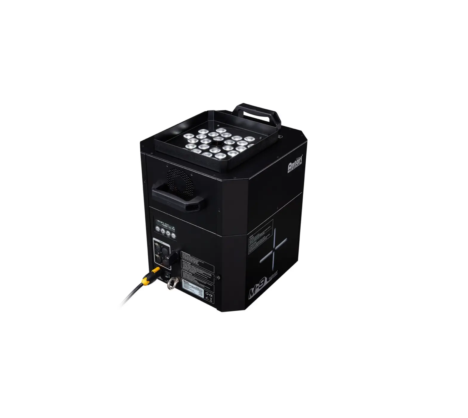
- 1 x M-9 RGBAW Fogger
- 1 x W-2 Wireless Remote
- 1 x Power Cord
- 1 x User Manual
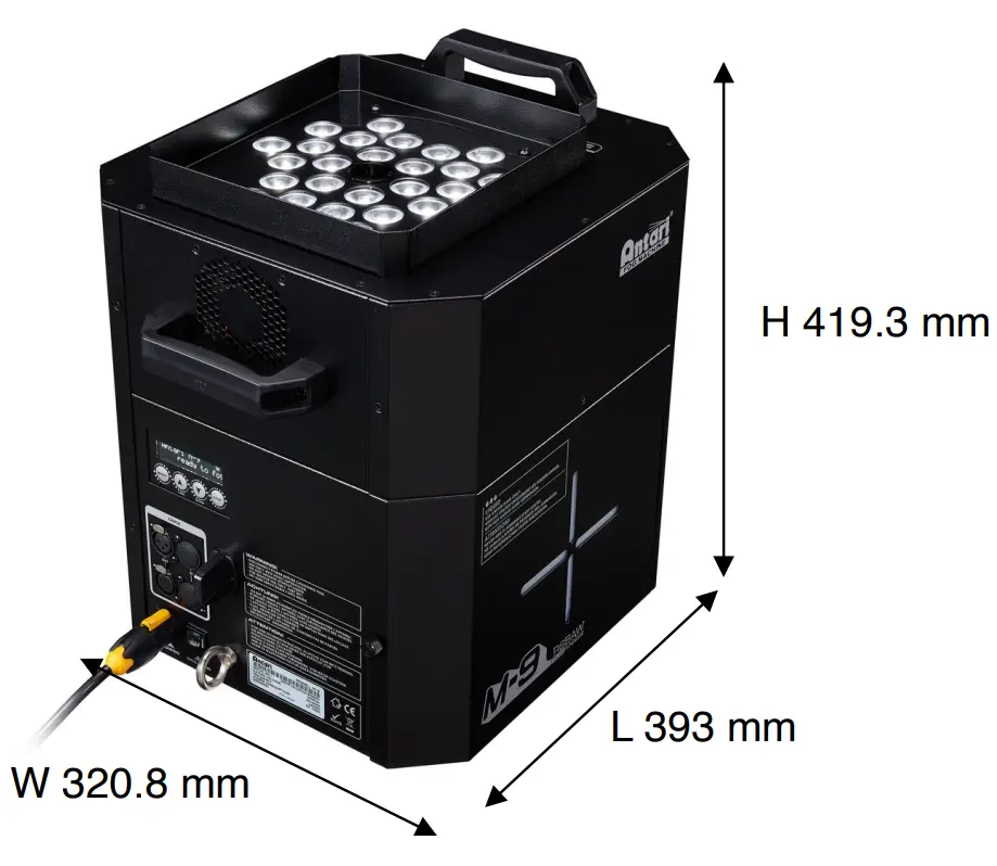
Product Dimension
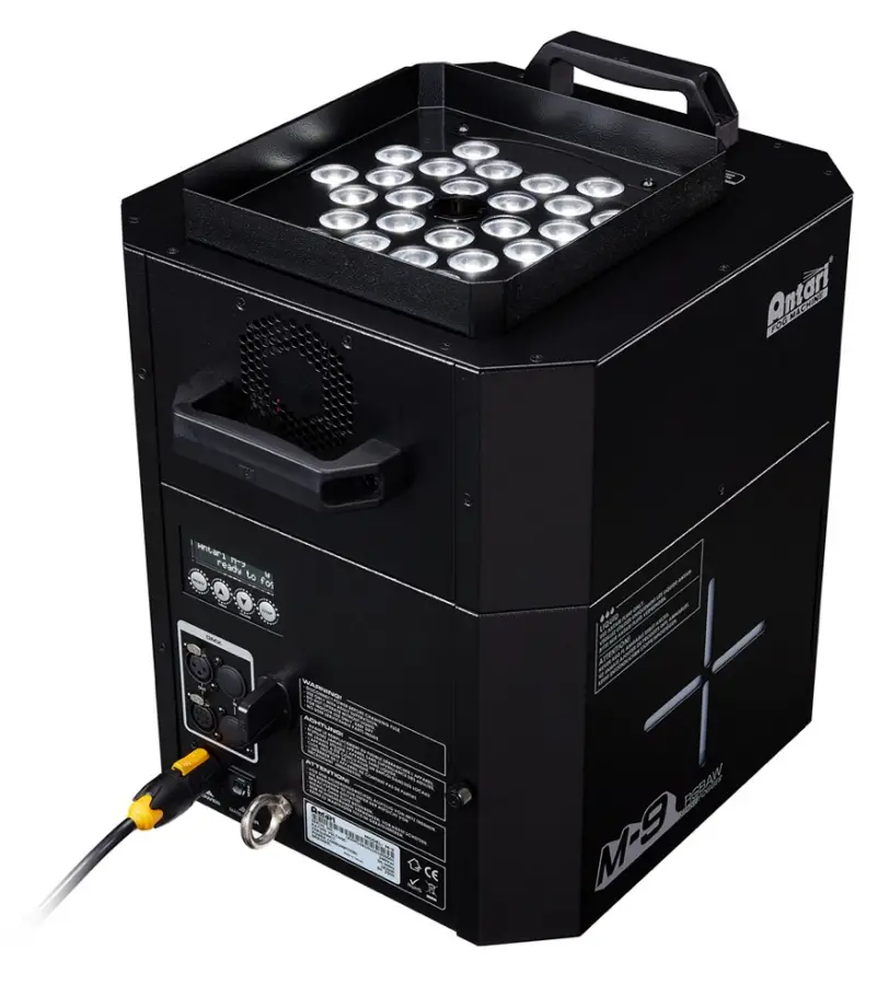
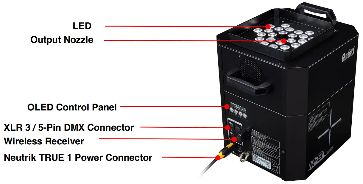
Product Overview
Setting Up
Step 1: Place the machine on a flat surface and in a suitably large area with at least 50 cm open space around the machine.
Step 2: Fill the fluid tank with Antari approved fluid.
Step 3: Connect the machine to suitably rated power supply. To determine the power requirement for the machine refer to the label on the back of the machine.
| Please read the following safety information carefully before operating the machine. Information includes important safety information about installation, usage, and maintenance. Pay attention to all warning labels and instructions in this manual and printed on the machine. |
Step 4: Turn on the machine and allow it to heat up. Heat up takes approximatley 14 mintues. Once the machine has reached operating temperature, the LCD display will show “Ready To Fog”. Now the machine is ready for operation.
Step 5: To start making fog, locate the Volume button on the control panel, and press the button to start making fog.
Step 6: To turn off the machine,press STOP button and turn Powercon to the OFF position.
Operation
Control Panel Operation
The machine can be operated with an onboard digital control interface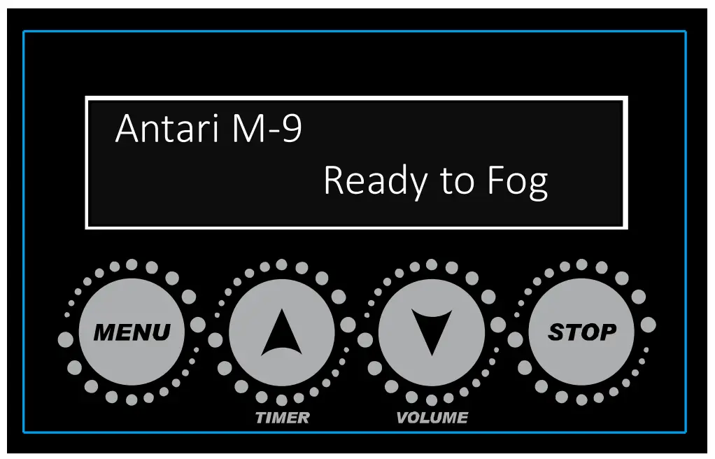
| Button | Function |
| [MENU] | Scroll through setting menu |
| ▲[UP]/[TIMER] | Up/Activate Timer function |
| ▼[DOWN]/[VOLUME] | Down/Activate Volume function |
| [STOP] | Deactivate Timer/Volume function |
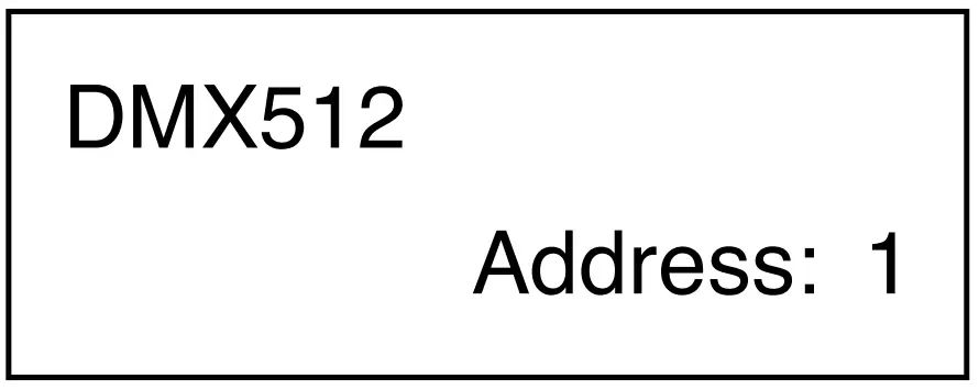 | Set DMX address from 1 to 503, 10 channels 1 to 498, 15 channels 1 to 488, 25 channels |
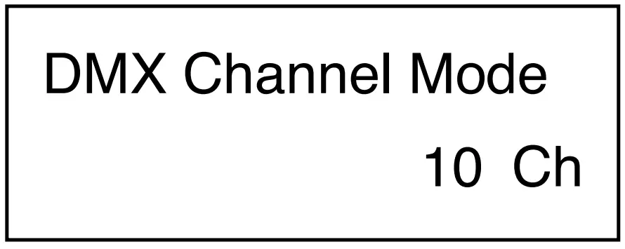 | Set DMX channel mode 10, 15 or 25 channels |
 | Set machine as Master of Slave unit |
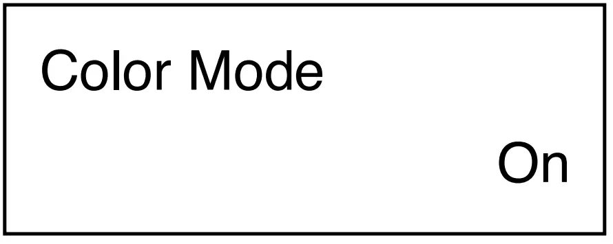 | Turn LED On or Off |
 | Set LED output color from macro 1 to 25 |
 | Set LED chase from 1 to 8 |
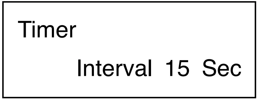 | Set interval from 15 to 360 seconds |
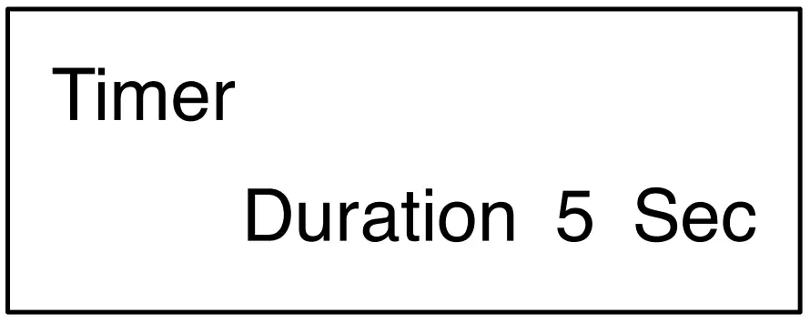 | Set duration from 1 to 5 seconds |
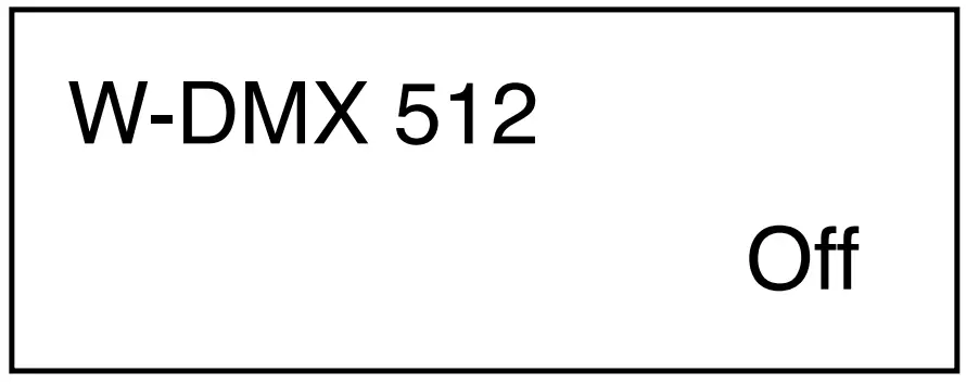
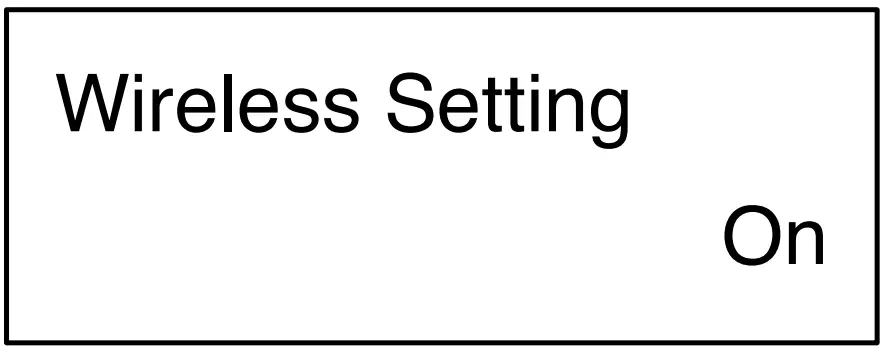 | Turn On or Off wireless control |
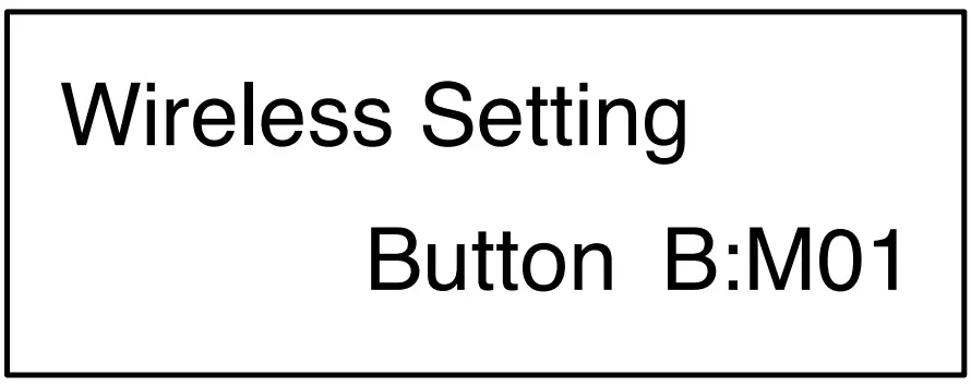
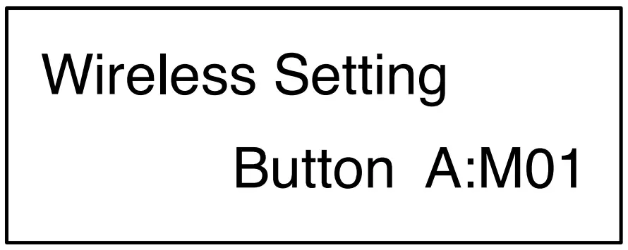 | Set wireless remote button function macro color 1 to 25 or chase 1 to 8. |
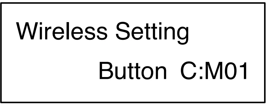
 | Set wireless remote button function macro color 1 to 25 or chase 1 to 8. |
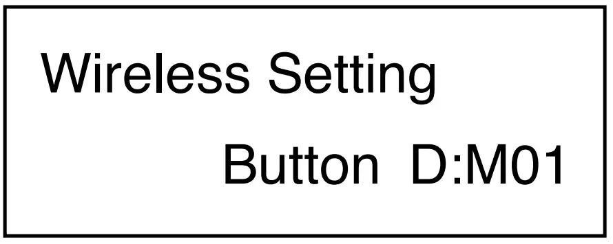
 | Set wireless remote button function macro color 1 to 25 or chase 1 to 8 |
 | Setting for LED to turn on with fog only or always on. |
 | Set LED delay time from 0 to 5 seconds. |
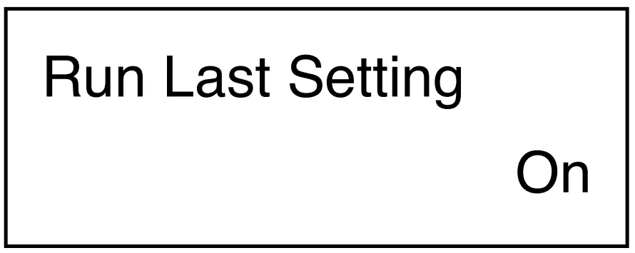
 | Turn On/Off run last setting function |
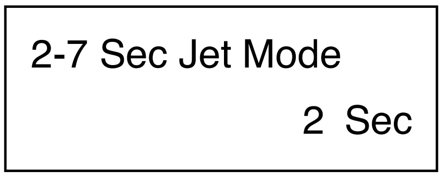
 | Turn On/Off Jet Mode, set time from 2 to 7 seconds. |
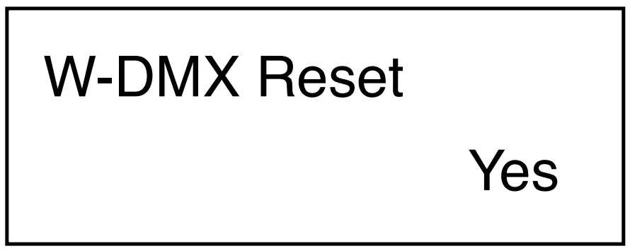 | Reset W-DMX connection |
 | Set Fog Output from 20 to 100% |
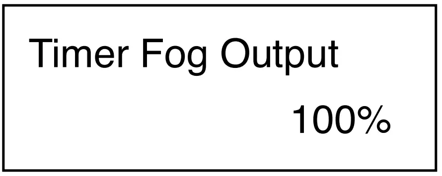 | Set Timer Fog Output from 20 to 100% |
DMX Connector Pin Assignment
The machine provides 3 or 5 pin XLR connector for DMX connection. The diagram below indicates pin assignment information.
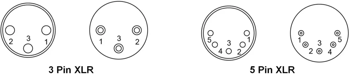
| Pin | Function |
| 1 | Ground |
| 2 | Data- |
| 3 | Data+ |
| 4 | N/A |
| 5 | N/A |
DMX Operation
Making the DMX Connection – Connect the machine to a DMX controller or to one of the machines in the DMX chain. The machine uses both 3-pin and 5-pin XLR connector for DMX connection, the connector is located on the rear of the machine.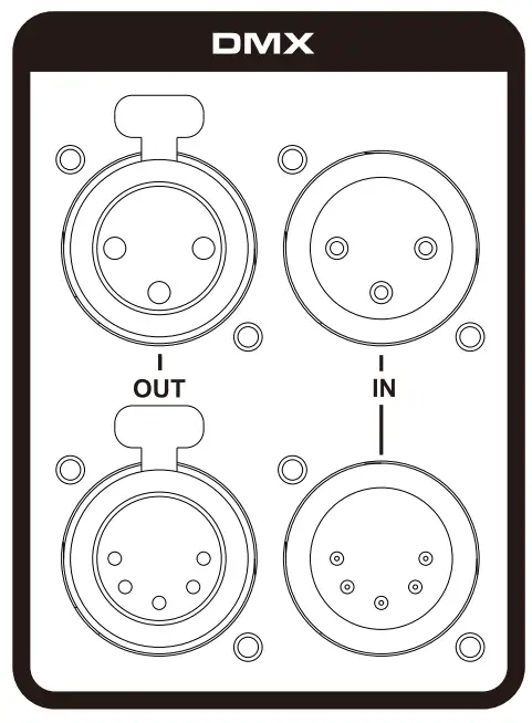
DMX Channel Function
10 Channel Mode
Channel | DMX Value Range | Function |
| 1 | 0 – 4 5 – 255 | Fog Off |
2 | 0-255 | Red LED 0-100% |
| 3 | 0-255 | Green LED 0-100% |
4 | 0-255 | Blue LED 0-100% |
| 5 | 0-255 | Amber LED 0-100% |
6 | 0-255 | White LED 0-100% |
| 7 | 1-30 31-60 61-90 91-120 121-150 151-180 181-210 211-255 | Chase 1 |
8 | 0-255 | Chase Speed 0- 255 step per min |
| 9 | 0-255 | Master Dimmer 0-100% |
10 | 0-255 | Strobe 1-20 Hz |
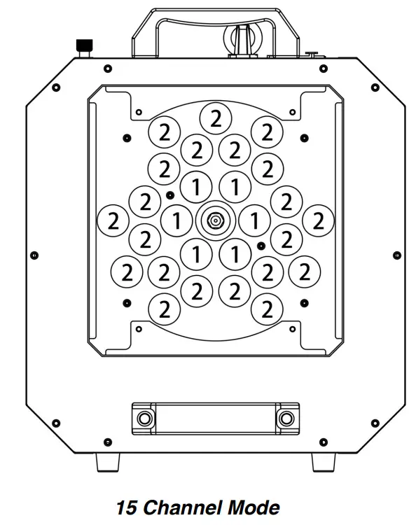
15 Channel Mode
Channel | DMX Value Range | Function |
| 1 | 0 – 4 5 – 255 | Fog Off |
2 | 0-255 | Red Zone 1 0-100% |
| 3 | 0-255 | Green Zone 1 0-100% |
4 | 0-255 | Blue Zone 1 0-100% |
| 5 | 0-255 | Amber Zone 1 0-100% |
6 | 0-255 | White Zone 1 0-100% |
| 7 | 0-255 | Red Zone 2 0-100% |
8 | 0-255 | Green Zone 2 0-100% |
| 9 | 0-255 | Blue Zone 2 0-100% |
10 | 0-255 | Amber Zone 2 0-100% |
| 11 | 0-255 | White Zone 2 0-100% |
12 | 1-30 31-60 61-90 91-120 121-150 151-180 181-210 211-255 | Chase 1 Chase 2 Chase 3 Chase 4 Chase 5 Chase 6 Chase 7 Chase 8 |
| 13 | 0-255 | Chase Speed 0- 255 step per min |
14 | 0-255 | Master Dimmer 0- 100% |
| 15 | 0-255 | Strobe 1-20 Hz |
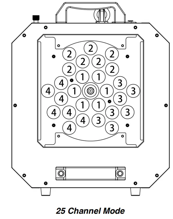
25 Channel Mode
Channel | DMX Value Range | Function |
| 1 | 0 – 4 5 – 255 | Fog Off |
2 | 0-255 | Red Zone 1 0-100% |
| 3 | 0-255 | Green Zone 1 0-100% |
4 | 0-255 | Blue Zone 1 0-100% |
| 5 | 0-255 | Amber Zone 1 0-100% |
6 | 0-255 | White Zone 1 0-100% |
| 7 | 0-255 | Red Zone 2 0-100% |
8 | 0-255 | Green Zone 2 0-100% |
| 9 | 0-255 | Blue Zone 2 0-100% |
10 | 0-255 | Amber Zone 2 0-100% |
| 11 | 0-255 | White Zone 2 0-100% |
12 | 0-255 | Red Zone 3 0-100% |
| 13 | 0-255 | Green Zone 3 0-100% |
14 | 0-255 | Blue Zone 3 0-100% |
| 15 | 0-255 | Amber Zone 3 0-100% |
16 | 0-255 | White Zone 3 0-100% |
| 17 | 0-255 | Red Zone 4 0-100% |
18 | 0-255 | Green Zone 4 0-100% |
| 19 | 0-255 | Blue Zone 4 0-100% |
20 | 0-255 | Amber Zone 4 0-100% |
| 21 | 0-255 | White Zone 4 0-100% |
22 | 1-30 31-60 | Chase 1 Chase 2 Chase 3 Chase 4 Chase 5 Chase 6 Chase 7 Chase 8 |
| 23 | 0-255 | Chase Speed 0- 255 step per min |
24 | 0-255 | Master Dimmer 0 100% |
| 25 | 0-255 | Strobe 1-20 Hz |
LED Zone Control
RDM Control
The M-9 RGBAW Stage Fog Machine is RDM enabled, allowing control system to configure, mointor and manage. See below table for supported RDM parameters
Value | RDM Parameter ID’s | GET Allowed | SET Allowed |
| 0x0001 | DISC_UNIQUE_BRANCH | ||
0x0002 | DISC_MUTE | ||
| 0x0003 | DISC_UN_MUTE | ||
0x0030 | STATUS_MESSAGE | O | |
| 0x0050 | SUPPORTED_PARAMETERS | O | |
0x0051 | PARAMETER_DESCRIPTION | O | |
| 0x0060 | DEVICE_INFO | O | |
0x0070 | PRODUCT_DETAIL_ID_LIST | O | |
| 0x0080 | DEVICE_MODEL_DESCRIPTION | O | |
0x0081 | MANUFACTURER_LABEL | O | |
| 0x0082 | DEVICE_LABEL | O | O |
0x00C0 | SOFTWARE_VERSION_LABEL | O | |
| 0x00E0 | DMX_PERSONALITY | O | O |
0x00E1 | DMX_PERSONALITY_DESCRIPTION | O | |
| 0x00F0 | DMX_START_ADDRESS | O | O |
0x0200 | SENSOR_DEFINITION | O | |
| 0x0201 | SENSOR_VALUE | O | |
0x0400 | DEVICE_HOURS | O | |
| 0x1000 | IDENTIFY_DEVICE | O | O |
Wireless Operation
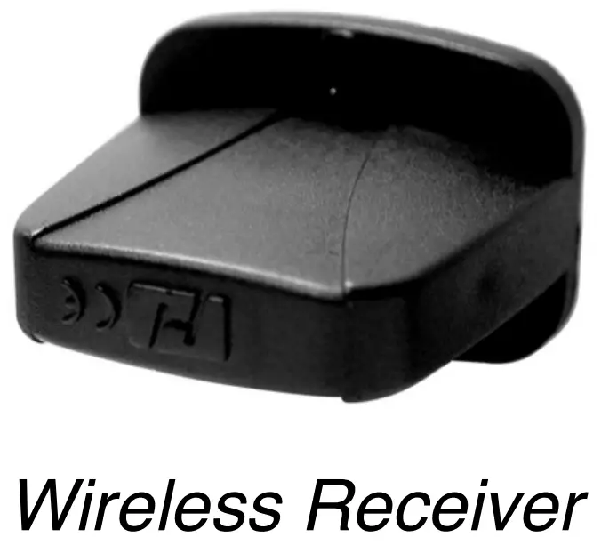
Wireless remote control system W-2 consist of a transmitter equipped with four buttons to activate four user configurable LED setting and fog; with an onboard receiver attach to the rear panel of M-9 RGBAW
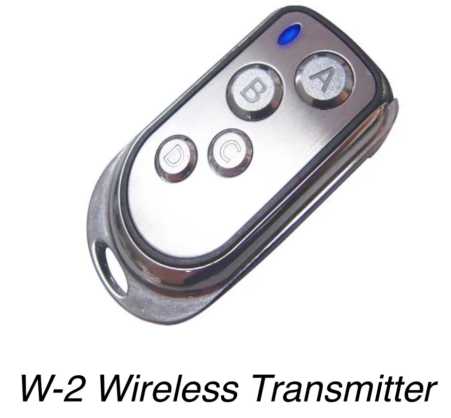
Wireless settings are configurable through onboard control panel, refer to control menu section to setup each buttons.
In an open unobstructed space the effective distance is 50 meters, the effective distance depending on obstacle level is 10-25 meters.
Registering transmitter
The transmitter can be paired or deleted from the receiver. Each receiver can pair up to 10 transmitters. Follow the steps below to pair or delete a transmitter from the receiver.
Step 1: Power off M-9 RGBAW Fogger
Step 2: Press and hold [DOWN] button
Step 3: Turn power on and release [DOWN] button when LCD display blinks
Step 4: Follow the menu instruction to pair or delete transmitter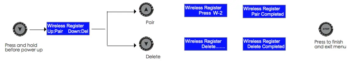
Transmitter battery replacement
f the effective distance appears to be decreased, it is possible the battery level is low and require replacement. In order to replace the battery, undo the three screws on the back of transmitter to release the cover. Replace with the same type and specification of battery which is 27A 12V
Status of W-DMX Connection (Optional)
| Symbol on the Liquid Crystal Display | Status of W-DMX connection |
 | Transmitter not assigned |
 | Transmitter assigned, No DMX signal |
 | Transmitter link lost or linking to transmitter |
 | Transmitter assigned, DMX signal received |
Fluid
Use Antari FLC water-based Fluid for the best effect for the M-9 RGBAW Fogger. The machine is tested and calibrated with this liquid to get the best output performance.
Warranty will be voided if any other type of liquid is used, improper use of liquid may lead to machine failure and malfunction.
Service and Maintenance
- Do not allow the machine to become contaminated.
- Remove dust from air vents with air compressor, vacuum or a soft brush.
- Only use a damp cloth to clean the casing.
- Before storing run distilled water through the system to help avoid condensing the pump or heater.
- It is recommended to run the machine on a monthly basis in order to achieve best performance and output condition.
- Excessive dust, liquid and dirt built up will degrade performance and cause overheating.
Breaker Reset
| Please read the following safety information carefully before operating the machine. Information includes important safety information about installation, usage, and maintenance. Pay attention to |
Step 1: Disconnect AC power
Step 2: Flip breaker to ON position
Step 3: Turn on machine to test
Breaker
100V = 16A 250V
120V = 15A 250V
240V = 9A 250V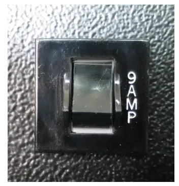
Technical Specifications
| Input voltage | US model : AC 100-120V, 50 / 60Hz 15.2A |
| EU model : AC 220-240V, 50 / 60Hz 7.6A | |
| Rated power | 1820 W |
| Light Source | 1820 W |
| Warm-up time | 14 minutes (approx) |
| Fluid consumption | 400 ml / min (100% output) |
| Fluid tank capacity | 6 Liters |
| Compatible fluid | Antari FLC Super Light Fog Fluid |
| Ambient temp / range | 0℃ – 40℃ (32℉-104℉) |
| Output | 10 meters height |
| DMX 512, Timer, Manual, Wireless | |
| Master / Slave | |
| Wireless DMX (Optional) | |
| DMX channels | 10 / 15 / 25 channels |
| Connection | Neutrik TRUE1 Connector (Power) |
| XLR 3-pin and XLR 5-pin (DMX) | |
| Optional accessories | WTR-90 Wireless DMX |
| Dimension | L 393 W 320.8 H 419.3 mm |
| Weight | 25 kg (55.1 lbs) |
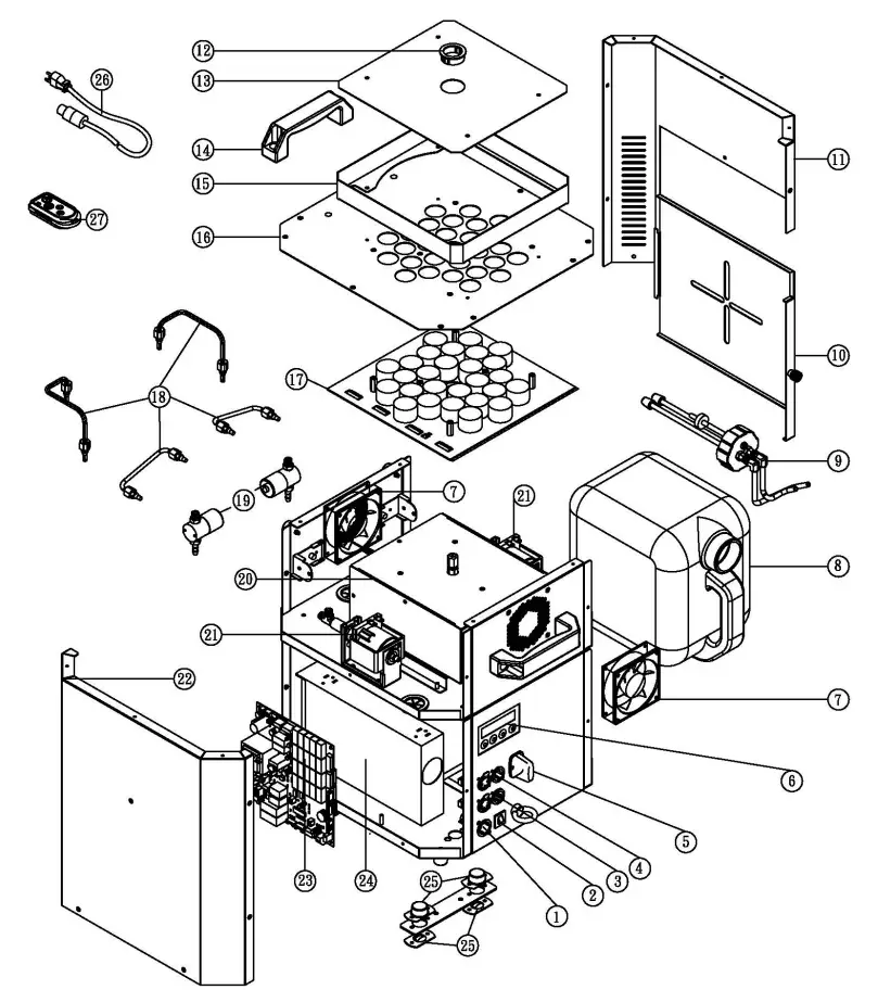
SPARE PARTS OF M-9
| ① | C04312621 | Power Inlet |
| ② | C04101400 | Breaker |
| ③ | DMX5POOA5 | P.C Board DMX 5Pin |
| ④ | DMX3POOAB | P.C Board DMX 3Pin |
| ⑤ | W-2RA | Wireless Receiver(l20V |
| ⑥ | M-9-PCBC | Control P.C Board |
| ⑦ | M-9-FAN | Fan |
| ⑧ | TK0806000 | Tank |
| ⑨ | M-9-TKC | Tank Cap (Group) |
| ⑩ | M00900300 | Steel Case |
| ⑪ | M0090RHOO | Steel Case |
| ⑫ | D04013000 | Snap Bushing |
| ⑬ | C02000740 | LED Protection Sheet |
| ⑭ | 02013500 | Handle |
| ⑮ | M00900500 | Steel Case |
| ⑯ | M00900HOO | Steel Case |
| ⑰ | M-9-LED | LED (Group) |
| ⑱ | M-9-CP | Brass Tube (Group) |
| ⑲ | M-9-LUS | Solenoid Valve (Group)(l20V) |
| ⑳ | M-9-H | Heater (Group)(120V) |
| ㉑ | PAOEX5A20 | Pump (Group)(l20V) |
| ㉒ | 0090LHOO | Steel Case |
| ㉓ | M- 9-PCB | Main P.C Board(l20V) |
| ㉔ | -9-POW | LED Power Supply |
| ㉕ | M-9-HB | Hanging Bracket (Group) |
| ㉖ | CA014205 | Power Cord & Plug(120V) |
| ㉗ | W-2A | Wireless Transmitter(l20V) |