
veration A2C1824820001 AcquaLink EngineBox Single Engine

Description
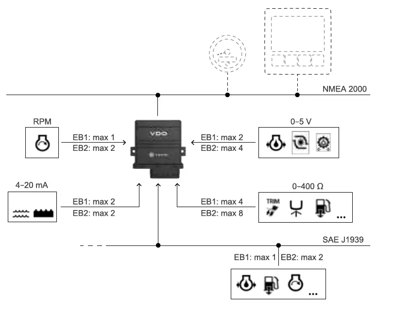
EngineBox is an NMEA 2000® gateway suited for motor boat refitting. EngineBox is able to convert various signals into NMEA 2000 strings so that all data is shared with all devices (gauges, display, etc.) in the NMEA 2000 network. Converted signals are: analog engine RPM, analog 4–20 mA, 0–5 V, 0–400 Ω and SAE J1939 signals. The single engine version can manage: one engine with output in frequency, one engine with SAE J1939 output and eight analog inputs. The dual engine version can manage: two engines with output in frequency, two engines with SAE J1939 output and 14 analog inputs. Designed according to international standards, it is suited for installation in an engine room, in coincidental presence of gas and high pressure liquids at high temperatures and flammable. It manages various sensors, both VDO and third party that can be set and calibrated via the VDO Marine Configuration Tool.
Box contents
- EngineBox
- Cable with MW 100 32 pin connector and lock device
- Installation Kit A2C1470220001
- These instructions with safety instructions
Inputs
EB1
- 4 analog inputs 0-400 Q
- 2 analog inputs 0-5 VN
- 2 analog inputs 4-20 mA
- 1 frequency input 04kHz
- 1 SAE J1939 input
- 1 NMEA 2000.
EB2
- 8 analog inputs 0-400 Q
- 4 analog inputs 0-5V
- 2 analog inputs 4-20 mA
- 2 frequency inputs 04 kHz
- 2 SAE J1939 input
- 1 NMEA 2000
Architecture
Accessories
| Part number | Description |
| A2C96243700 | NMEA2000 cable 0.5 m |
| A2C96243800 | NMEA2000 cable 2 m |
| A2C96244000 | NMEA2000 cable 6 m |
| A2C39312700 | NMEA 2000 T splitter |
| A2C39312500 | NMEA 2000 inline terminal |
Before assembly
NOTICE: short circuit. Cable burning, battery explosion. Remove the ignition key and detach the battery negative pole terminal. Refer to the safety instructions on the back of this sheet.
NOTICE: place the device at least 50 cm away from any magnetic compass.
Assembly
- Place the device on the wall with the connector and LED facing down.
- Secure the device with the two supplied screws.
- Wire all sensors.
- Insert the connector and lock it with the specific device.
- Set and calibrate sensors using the Veratron Configuration Tool.
Micro-pack MW100 connector pinout (female, cable side)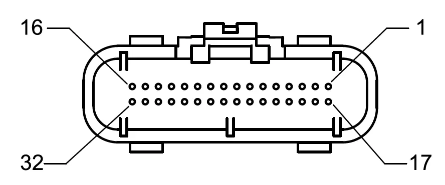
| Pin | EB1 | EB2 | Range | ||
| Function | Color | Function | Color | ||
| 1 | Power Supply GND | Black | Power supply GND | Black | – |
| 2 | Power Supply GND | Black | Power supply GND | Black | – |
| 3 | – | – | Engine 2 frequency | White/Black | 0–4 kHz |
| 4 | Engine frequency GND | Green/White | Engine 1 frequency GND | Green/White | – |
| 5 | NMEA 2000: CAN_L | Blue | NMEA 2000: CAN_L | Blue | – |
| 6 | NMEA 2000: CAN_H | White | NMEA 2000: CAN_H | White | – |
| 7 | NMEA 2000: SHIELD | – | NMEA 2000: SHIELD | – | – |
| 8 | Engine resistive sensor | Blue | Engine 1 resistive sensor | Blue | 0–400 Ω |
| 9 | Engine resistive sensor | Pink | Engine 1 resistive sensor | Pink | 0–400 Ω |
| 10 | Engine resistive sensor | Orange | Engine 1 resistive sensor | Orange | 0–400 Ω |
| 11 | Engine resistive sensor | Violet | Engine 1 resistive sensor | Violet | 0–400 Ω |
| 12 | Engine pressure sensor | Gray | Engine 1 pressure sensor | Gray | 0–5 V |
| 13 | – | – | Engine 2 pressure sensor | Turquoise | 0–5 V |
| 14 | Engine capacitive sensor | Brown/White | Engine 2 capacitive sensor | Brown/White | 4–20 mA |
| 15 | – | – | Engine 2 J1939:CAN_L | Fuchsia/white | – |
| 16 | J1939:CAN_L | Light Blue/White | Engine 1 J1939:CAN_L | Light Blue/White | – |
| 17 | Power Supply 12/24 V dc | Red | Power supply 12/24 V dc | Red | 8–32 V dc |
| 18 | Ignition | Yellow | Ignition | Yellow | 12/24 V dc |
| 19 | – | – | Engine 2 frequency GND | White | – |
| 20 | Engine Frequency | Green | Engine 1 frequency | Green | 0–4 kHz |
| 21 | NMEA 2000: GND | Black | NMEA 2000: GND | Black | – |
| 22 | NMEA 2000: Power | Red | NMEA 2000: Power | Red | 12 V dc |
| 23 | – | – | Engine 2 resistive sensor | Blue/White | 0–400 Ω |
| 24 | – | – | Engine 2 resistive sensor | Pink/White | 0–400 Ω |
| 25 | – | – | Engine 2 resistive sensor | Orange/White | 0–400 Ω |
| 26 | – | – | Engine 2 resistive sensor | Violet/White | 0–400 Ω |
| 27 | 0–5 V | Gray/White | Engine 1 pressure sensor | Gray/White | 0–5 V |
| 28 | – | – | Engine 2 pressure sensor | Turquoise/White | 0–5 V |
| 29 | – | – | – | Red/White | – |
| 30 | Engine capacitive sensor | Brown | Engine 1 capacitive sensor | Brown | 4–20 mA |
| 31 | – | – | Engine 2 J1939:CAN_H | Fuchsia | – |
| 32 | J1939:CAN_H | Light Blue | Engine 1 J1939:CAN_H | Light Blue | – |
M12 NMEA 2000 connector pinout (male, cable side)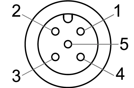
| Pin | Function | Color |
| 1 | Shield | – |
| 2 | Signal NET-S | Red |
| 3 | Power NET-C | Black |
| 4 | Signal NET-H | White |
| 5 | Signal NET-L | Blue |
Used sensors
| Input type | Input type | Max inputs for EB2 | Sensor | Range |
| 0–400 Ω (*) | 4 | 8 | Trim | 167–10 Ω |
| Engine coolant pressure | 0–400 Ω | |||
| 240–33 Ω | ||||
| Engine oil pressure | 0–400 Ω | |||
| 10–184 Ω | ||||
| 240–33,5 Ω | ||||
| Engine oil temperature | 0–400 Ω | |||
| Transmission oil pressure | 0–400 Ω | |||
| 10–184 Ω | ||||
| 240–33,5 Ω | ||||
| Transmission oil temperature | 0–400 Ω | |||
| Fresh water level | 0–400 Ω | |||
| Rudder angle | 0–400 Ω | |||
| 0–180 Ω | ||||
| 0–90 Ω | ||||
| Fuel level | 0–400 Ω | |||
| 240–33,5 Ω | ||||
| 0–5 V (*) | 2 | 4 | Pressure 365-100-010-121C | 10 bar |
| Pressure 365-100-016-121C | 16 bar | |||
| Pressure 365-100-030-121C | 30 bar | |||
| 4–20 mA (*) | 2 | 2 | Fresh water level | 4–20 mA |
| Waste water level | 4–20 mA | |||
| 0–4 kHz | 1 | 2 | Engine rpm | Based on the pulse per rpm factor. Configured with VDO Marine Configuration Tool. |
| SAE J1939 | 1 | 2 | See Supported SAE J1939 messages | – |
| NMEA 2000 | 1 | 1 | See Supported NMEA 2000 messages | – |
Note ranges configured via VDO Marine Configuration Tool.
Supported SAE J1939 messages
| PGN | SPN | Descrizione |
| 61444 | 190 | Engine Speed |
| 65226 | 624 | Amber Warning |
| 65226 | 623 | Red Stop |
| 65226 | 987 | Protect lamp |
| 65226 | 3098 | MIL |
| 65253 | 247 | Engine Total Hours of Operation |
| 65262 | 110 | Engine Coolant Temperature |
| 65262 | 175 | Engine Oil Temperature 1 |
| 65263 | 100 | Engine Oil Pressure |
| 65263 | 109 | Engine Coolant Pressure |
| 65266 | 183 | Engine Fuel Rate |
| 65270 | 102 | Engine Turbocharger Boost Pressure |
| 65270 | 173 | Engine Exhaust Gas Temperature |
| 65272 | 177 | Transmission Oil Temperature |
| 65272 | 127 | Transmission Oil Pressure |
| 65276 | 96 | Fuel Consumption |
| 65279 | 97 | Water In Fuel Indicator |
Supported NMEA 2000 messages
| PGN | Descrizione |
| 127245 | Rudder |
| 127488 | Engine Parameters, Rapid Update |
| 127489 | Engine Parameters, Dynamic |
| 127493 | Transmission Parameters, Dynamic |
| 127497 | Trip Fuel Econsumtption, Engine |
| 127505 | Fluid level |
| 127508 | Battery status |
| 130576 | Trim Tab Status |
General features
| Material | PA6-GF30 |
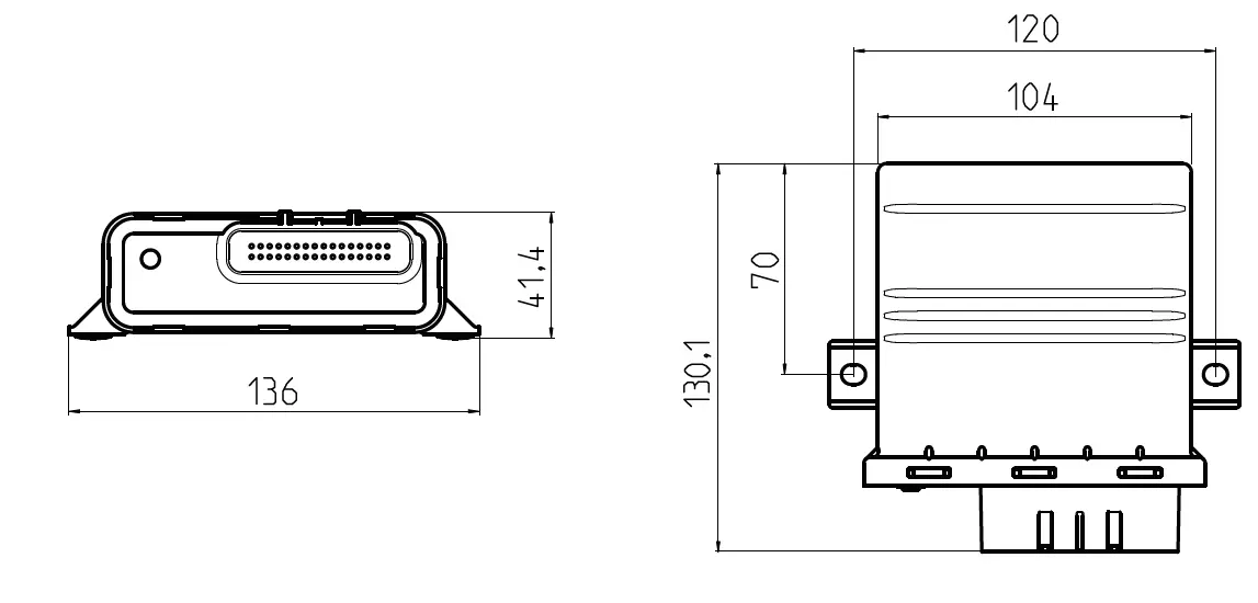
| Dimension [mm] | See figures |
| Protection grade | IP X9k-f IEC 60945 protected |
| Flammability | UL-94 V0 |
| Connectors | Micro-Pack MW100 NMEA 2000 Micro-C M12 |
| Status LED | Off: not powered, green fixed: powered without data transmission, green flashing: data transmission underway |
| Available variations (*) | EB1: single engine, EB2: dual engine |
| Input data | NMEA 2000, SAE J1939, frequency 0–4 kHz, resistive 0–400 Ω. capacitive 4–20 mA, 0–5 V. |
| Output data | NMEA 2000 |
| Start-up time | < 1 s |
Note Engine Box detects the presence of the single or double engine cable.
Environmental specifications
| Working temperature | From -25 to +70 °C |
| Storage temperature | From -40 to +85 °C |
Electrical specifications
| Rated voltage | 12 / 24 V dc |
| Voltage tolerance | 9–32 V dc |
| Working current | 150 mA @ 12V |
| Reverse polarity protection | Yes |
| Short circuit protection | Yes, 1 minute |
Conformity
| Conformity |  |
| Directives | 2011/65/EU (Electrical-electronic equipment hazardous substances) |
| Reference standards | EN 60945:2002 ISO 8846:1990 IEC 60079-0:1983 DIN EN 60079-11 EN ISO 15584:2001 |
Disposal instructions
Separate waste and use the collection centers indicated by the government or local public agencies. Correct disposal and recycling help to prevent potentially harmful consequences to the environment and population.
Dimensions
Safety information
- The product was developed, manufactured and inspected according to the basic safety requirements of EC Guidelines and state-of-the-art technology.
- The unit is designed for use in the leisure marine market.
- The unit is designed for use in grounded vehicles and machines as well as in nautical sports, including non-classified commercial shipping.
- Use our product only as intended. Use of the product for reasons other than its intended use may lead to personal injury, property damage or environmental damage.
- Before installation, check the vehicle documentation for vehicle type and any possible special features!
- Use the assembly plan to learn the location of the fuel/hydraulic/compressed air and electrical lines!
- Note possible modification to the vehicle, which must be considered during installation!
- To prevent personal injury, property damage or environmental damage, basic knowledge of motor vehicle/shipbuilding electronics and mechanics is required.
- Modifications or manipulations to the VDO product can affect safety. Consequently, you may not modify or manipulate the product!
- When removing/installing seats, covers, etc., ensure that lines are not damaged and plug-in connections are not loosened!
- Note all data from other installed units with volatile electronic memories.
Safety during installation:
- During installation, ensure that the product’s components do not affect or limit vehicle functions. Avoid damaging these components!
- Only install undamaged parts in a vehicle!
- During installation, ensure that the product does not impair the field of vision and that it cannot impact the driver’s or passenger’s head!
- A specialized technician should install the product. If you install the product yourself, wear appropriate work clothing. Do not wear loose clothing, as it may get caught in moving parts. Protect long hair with a hair net.
- When working on the on-board electronics, do not wear metallic or conductive jewelry such as necklaces, bracelets, rings, etc.. If work on a running engine is required, exercise extreme caution. Wear only appropriate work clothing as you are at risk of personal injury, resulting from being crushed or burned.
- Before taking any action, disconnect the negative terminal on the battery, otherwise you risk a short circuit. If the vehicle is supplied by auxiliary batteries, you must also disconnect the negative terminals on these batteries! Short circuits can cause fires, battery explosions and damages to other electronic systems. Please note that when you disconnect the battery, all volatile electronic memories lose their input values and must be reprogrammed.
- If working on gasoline boat motors, let the motor compartment fan run before beginning work.
- Pay attention to how lines and cable harnesses are laid so that you do not drill or saw through them!
- Do not choose to install the product in the mechanical and electrical airbag area!
- Do not drill holes or ports in load-bearing or stabilizing stays or tie bars!
- When working underneath the vehicle, secure it according to the specifications from the vehicle manufacturer.
- Note the necessary clearance behind the drill hole or port at the installation location.
- Required mounting depth: 65 mm.
- Drill small ports; enlarge and complete them, if necessary using taper milling tools, saber saw, keyhole saw or file. Debur edges. Follow the safety instructions of the tool manufacturer.
- Use only insulated tools, if work is necessary on live parts.
- Use only the multimeter or diode test lamps provided, to measure voltages and currents in the vehicle/machine or ship. Use of conventional test lamps can cause damage to control units or other electronic systems.
- The electrical indicator outputs and cables connected to them must be protected from direct contact and damage. The cables in use must have sufficient insulation and
- electric strength and the contact points must be safe from touch.
- Use appropriate measures to also protect the electrically conductive parts on the connected consumer from direct contact. Laying metallic, uninsulated cables and contacts is prohibited.
- Safety after installation:
- Connect the ground cable tightly to the negative terminal of the battery.
- Reenter/reprogram the volatile electronic memory values.
- Check all functions.
- Use only clean water to clean the components. Note the Ingress Protection (IP) ratings
Electrical connection:
- Note cable cross-sectional area!
- Reducing the cable cross-sectional area leads to higher current density, which can cause the cable cross-sectional area in question to heat up!
- When installing electrical cable, use the provided cable ducts and harnesses, however, do not run cables parallel to ignition cables or to cables that lead to large electricity consumers.
- Fasten cables with cable ties or adhesive tape. Do not run cables over moving parts. Do not attach cables to the steering column!
- Ensure that cables are not subject to tensile, compressive or shearing forces.
- If cables are run through drill holes, protect them using rubber sleeves or the like.
- Use only one cable stripper to strip the cable. Adjust the stripper so that stranded wires are not damaged or separated.
- Only use a soft soldering process or commercially available crimp connector to solder new cable connections!
- Only make crimp connections with cable crimping pliers. Follow the safety instructions of the tool manufacturer.
- Insulate exposed stranded wires to prevent short circuits.
- Caution: Risk of short circuit if junctions are faulty or cables are damaged.
- Short circuits in the vehicle network can cause fires, battery explosions and damage to other electronic systems. Consequently, all power supply cable connections must be provided with weldable connectors and be sufficiently insulated.
- Ensure ground connections are sound. Faulty connect connections can cause short circuits. Only connect cables according to the electrical wiring diagram.
- If operating the instrument on power supply units, note that the power supply unit must be stabilized and it must comply with the following standard: DIN EN 61000, Parts 6-1 to 6-4
Disclaimer:
The GPS Speed data (speed, course, position, time) is for information only. VDO does Veratron does not guarantee the data to always be accurate, correct or available.


 Dc Engine Retrofit Kit Instruction Manual")


