![]()
LED LIGHT ENGINE APPLICATION PROGRAM
RETROFIT KIT INSTALLATION MANUAL FOR CEILING MOUNTED LUMINAIRES
INSTALLATION INSTRUCTIONS
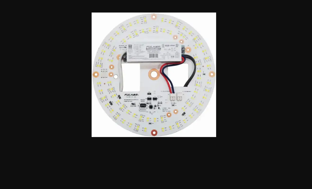
VividHorse Universal Voltage (120-277V) DC Engine Retrofit Kit
VKMUNV008RD930A
VKMUNV012RD930A
VKMUNV018RD930A
VKMUNV025RD930A
Reference spec sheet for full part numbers
1.0 INSTALLATION WARNINGS
- “THIS PRODUCT MUST BE INSTALLED IN ACCORDANCE WITH THE APPLICABLE INSTALLATION CODE BY A PERSON FAMILIAR WITH THE CONSTRUCTION AND OPERATION OF THE PRODUCT AND HAZARDS INVOLVED.”
- “WARNING – Risk of fire or electric shock. LED Retrofit kit installation requires knowledge of luminaires electrical systems. If not qualified, do not attempt installation. Contact a qualified electrician.”
- “WARNING – Risk of fire or electric shock. Install this kit only in the luminaires that has the construction features and dimensions shown in the photographs and/or drawings.”
- “WARNING – To prevent wiring damage or abrasion, do not expose wiring to edges of sheet metal or other sharp objects.”
- “WARNING – Risk of fire or electric shock. Luminaire wiring and electrical parts may be damaged when drilling for installation of LED retrofit kit. Check for enclosed wiring and components.”
- “CAUTION - RISK OF FIRE. CONSULT A QUALIFIED ELECTRICIAN TO ENSURE CORRECT BRANCH CIRCUIT CONDUCTOR.”
- THE RETROFIT KIT IS ACCEPTED AS A COMPONENT OF A LUMINAIRE WHERE THE SUITABILITY OF THE COMBINATION SHALL BE DETERMINED BY CSA OR AUTHORITIES HAVING JURISDICTION. PRODUCT MUST BE INSTALLED BY A QUALIFIED ELECTRICIAN IN ACCORDANCE WITH THE APPLICABLE AND APPROPRIATE ELECTRICAL CODES. THE INSTALLATION GUIDE DOES NOT SUPERSEDE LOCAL OR NATIONAL REGULATIONS FOR ELECTRICAL INSTALLATIONS
- Only those open holes indicated in the photographs and/or drawings may be made or altered as a result of kit installation. Do not leave any other open holes in an enclosure of wiring or electrical components.
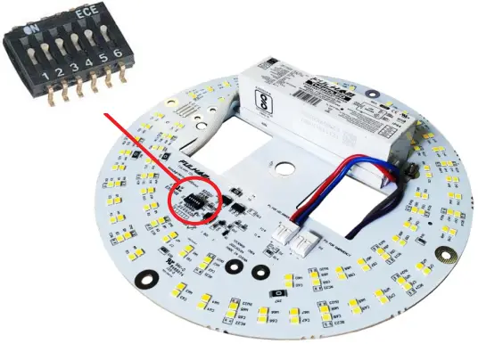
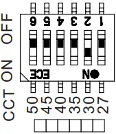
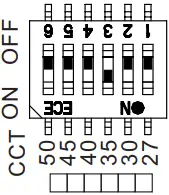
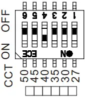
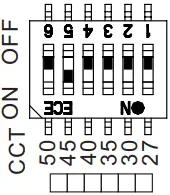
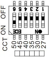
2.0 CCT SELECTION INDICATION
- The VividHorse DC Engine Retrofit Kit is a dual-channel LED product, that allows for CCT selection via the dip switch on the PCB. Available CCTs include 2700K, 3000K, 3500K, 4000K, 4500K and 5000K.
- A pre-set CCT will come from the factory. Check the product label or packaging to see the pre-set CCT level.
- Change the dip switch position to “ON” (1~6) to set the desired CCT level.
NOTE: ONLY keep one dip switch in the “ON” position, not doing so may result in an undesired CCT.
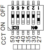
CCT Selection Dip Switch
CCT Indication Table
| 1 | 2 | 3 | 4 | 5 | 6 | |
| 2700K | ON | OFF | OFF | OFF | OFF | OFF |
| 3000K | OFF | ON | OFF | OFF | OFF | OFF |
| 3500K | OFF | OFF | ON | OFF | OFF | OFF |
| 4000K | OFF | OFF | OFF | ON | OFF | OFF |
| 4500K | OFF | OFF | OFF | OFF | ON | OFF |
| 5000K | OFF | OFF | OFF | OFF | OFF | ON |
2700K 3000K 3500K
4000K 4500K 5000K
Retrofit Kit Warning Label
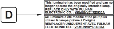
This luminaire has been modified and can no longer operate the originally intended lamp. REPLACE ONLY WITH FULHAM ELECTRONIC CO. : VKMUNV0**RD930A
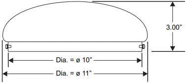
3.0 ORIGINAL LUMINAIRE DIMENSIONS
Original Luminaire
(Mfr: Lamar Lighting - Model: CDW11311PN1SW
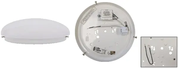
Minimum Luminaire Dimensions
- Remove all the original luminaire parts, hardware, lamp, and ballast in order to begin the retrofit.
- Original luminaire diffuser and original ground wire will need to be kept for this retrofit.
- This DC Engine Kit can be retrofitted into any surface wall or ceiling luminaire with a similar shape and diameter/height greater or equal to the minimum dimensions described above, or volume greater or equal to 195.28 cubic inches.
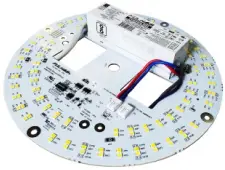
4.0 RETROFIT KIT COMPONENTS
Retrofit kit components will be provided as listed below:
UNV DC Engine Mounting Hardware

Input Power Connector Retrofit Labels
5.0 RECOMMENDED TOOLS (Not Included)
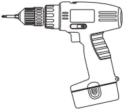
Power Drill W/ Philips Bit
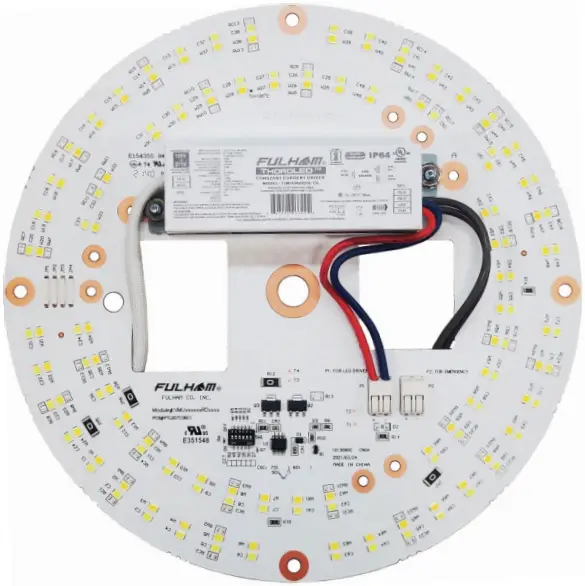
6.0 RETROFIT KIT DESCRIPTION
| ITEM | DESCRIPTION | QTY |
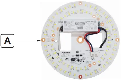
| A. | DC Engine | 1 |
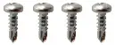
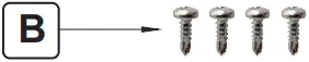
| B. | 6-20 X 3/8” Pan Head Self Drilling Screws | 4 |
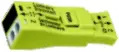
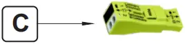
| C. | Input Connector | 1 |
| D. | Retrofit Labels | 2 |
7.0 RETROFIT KIT ASSEMBLY
1. Start by removing the original lamp, ballast and socket from the luminaire see Figure 1.
NOTE: The original luminare ground wire will need to be kept for this retrofit.
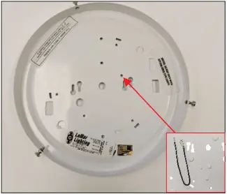
Figure 1
2. Pass the DC Engine (A) input power wires and dimming wires (if available) through the luminaire wire hole. See Figure 2.
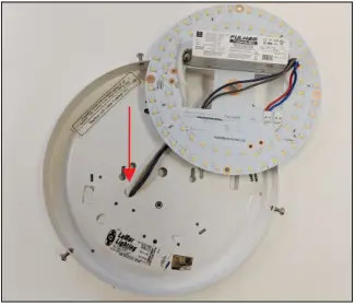
Figure 2
3. Place the DC Engine into the luminaire housing as shown in Figure 3.
NOTE: LED Engine must make direct contact with the back plate when installed in order to provide sufficient heat sinking to properly manage thermals for safety and warranty purposes.
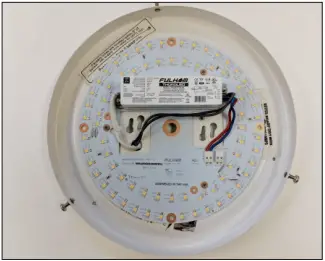
Figure 3
4. Use the supplied self-drilling screws (B) to attach the DC Engine (A) to the luminaires housing. See Figure 4.
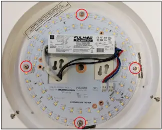
Figure 4
5. Place the provided labels in the outer space of the luminaire after the DC Engine installation has been completed. Labels must be clearly visible and should not be obscured by line voltage cables. See Figure 5.
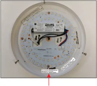 Figure 5
This luminaire has been modified and can no longer operate the originally intended lamp. REPLACE ONLY WITH FULHAM ELECTRONIC CO. : VKMUNV0**RD930A
6. Completed assembly should look like Figure 5.
7. Luminaire is now ready to be installed. Please see below for instructions on connecting line voltage to the luminaire.
Re-attach and secure the lens once installation is completed, retrofit should look like Figure 6.

Figure 6
Connecting Power to the DC Engine:
1) Connect the green wire (Ground) from the luminaire to the Ground that is being fed by the power source. Connect these two wires by using a wire connector with a minimum 18AWG rating.
2) Connect the white wire (Neutral) from the LED Engine to the Neutral being fed by the power source. Connect these two wires by using a wire connector with a minimum 18AWG rating.
3) Connect the Black wire (Line) from LED Engine to the Line being fed by the power source. Connect these two wires by using a wire connector with a minimum 18AWG rating.
8.0 WARRANTY
Please refer to LED Engine kit spec sheet for warranty information
Fulham Co. Inc.: 12705 South Van Ness Ave., Hawthorne, CA 90250 • Telephone: 1-323-779-2980 • Fax: 1-323-754-9060 [email protected] www.fulham.com
Installation Instructions subject to change without notice.
01/06/22
INS-VKM-RD_V3, Rev A
 Dc Engine Retrofit Kit Instruction Manual")
 Dc Engine Retrofit Kit Instruction Manual")


