TOYOTA A25 Force Engine
PARTS
ELECTRICAL WIRING ROUTING
- Location of Connector Joining Wire Harness and Wire Harness
- Location of Ground Points

- Location of Splice Points

HOW TO USE THIS MANUAL
The system shown here is an EXAMPLE ONLY. It is different to the actual circuit shown in the SYSTEM CIRCUITS SECTION.
OVERALL ELECTRICAL WIRING DIAGRAM
RELAY LOCATIONS
Engine Room J/B Engine Compart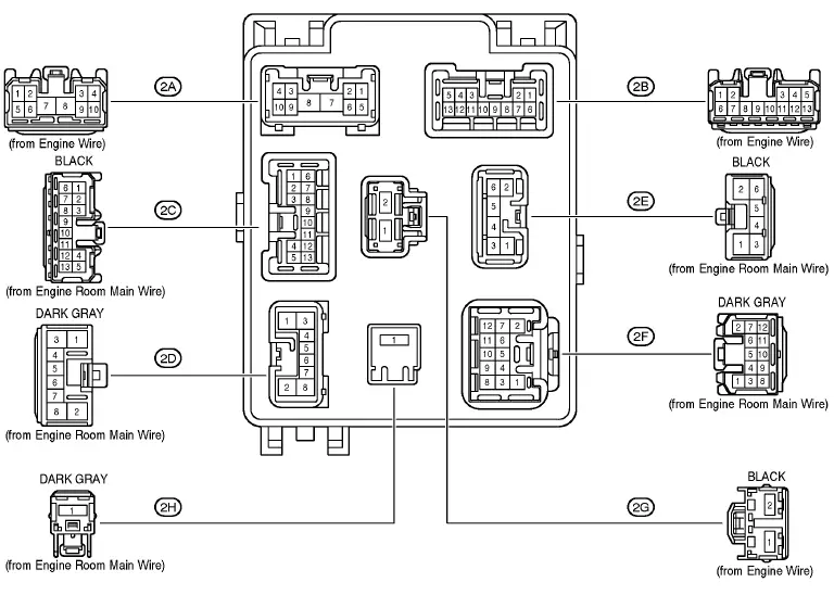
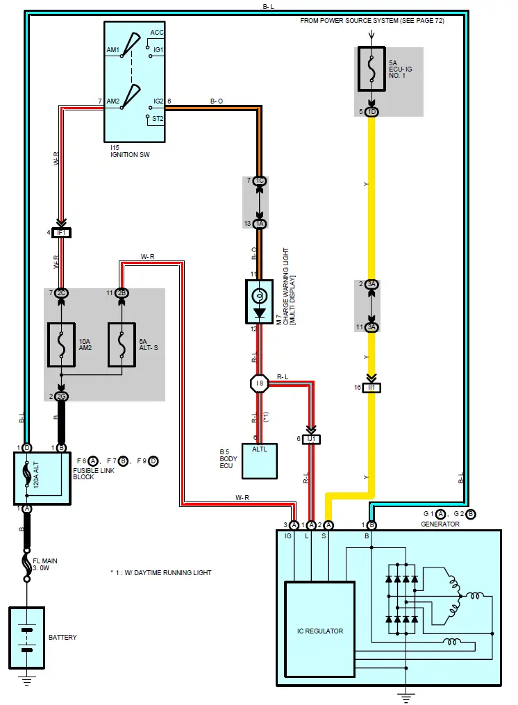
CHARGING
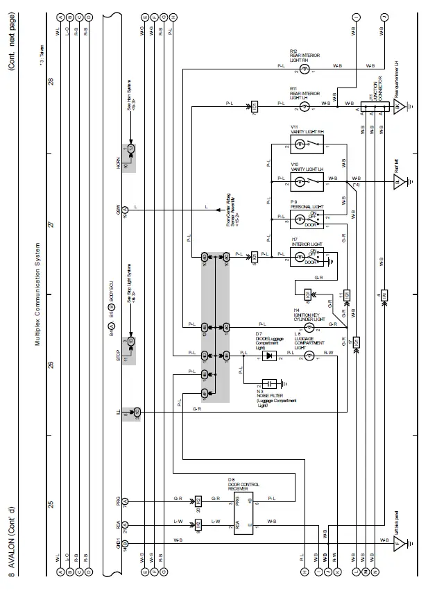
MULTIPLEX COMMUNICATION SYSTEM
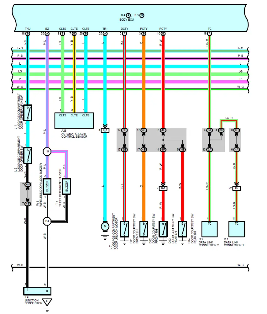
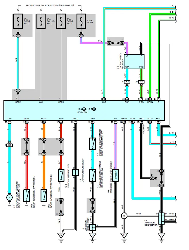
WIRELESS DOOR LOCK CONTROL
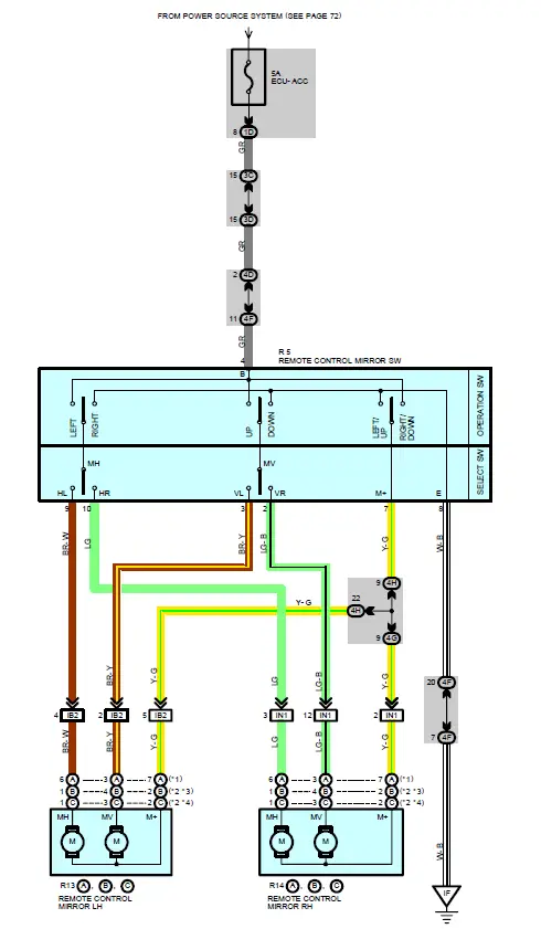
REMOTE CONTROL MIRROR (w/o DRIVING POSITION MEMORY)
SERVICE HINTS
R5 REMOTE CONTROL MIRROR SW
- 7-8 Continuity with the operation SW at UP or LEFT position
- 4-7 Continuity with the operation SW at DOWN or RIGHT position
- 4-GROUND Approx. 12 volts with the ignition SW at ACC or ON position
PARTS LOCATION
| Code | See Page | Code | See Page | Code | See Page | |||
| R5 | 47 (Column Shift) | R13 | B | 51 | R14 | B | 51 | |
| 49 (Floor Shift) | C | 51 | C | 51 | ||||
| R13 | A | 51 | R14 | A | 51 | |||
JUNCTION BLOCK AND WIRE HARNESS
| Code | See Page | Junction Block and Wire Harness (Connector Location) |
| 1D | 27 | Cowl Wire and Driver Side J/B (Lower Finish Panel) |
| 3C | 34 | Cowl Wire and J/B No.3 (Left Kick Panel) |
| 3D | ||
| 4D | 38 | Cowl Wire and J/B No.4 (Right Kick Panel) |
| 4F | 39 | Instrument Panel Wire and J/B No.4 (Right Kick Panel) |
| 4G | ||
| 4H |
CONNECTOR JOINING WIRE HARNESS AND WIR
| Code | See Page | Joining Wire Harness and Wire Harness (Connector Location) |
| IB2 | 56 (Column Shift) | Front Door LH Wire and Instrument Panel Wire (Left Kick Panel) |
| 60 (Floor Shift) | ||
| IN1 | 58 (Column Shift) | Front Door RH Wire and Instrument Panel Wire (Right Kick Panel) |
| 62 (Floor Shift) |
GROUND POINTS
| Code | See Page | Ground Points Location |
| IF | 56 (Column Shift) | Left Kick Panel |
| 60 (Floor Shift) |
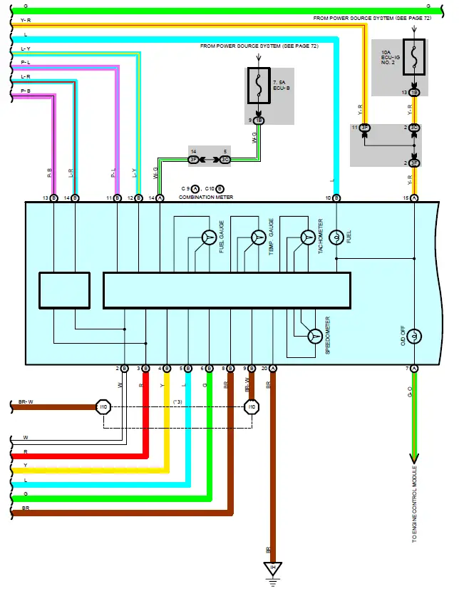
COMBINATION METER
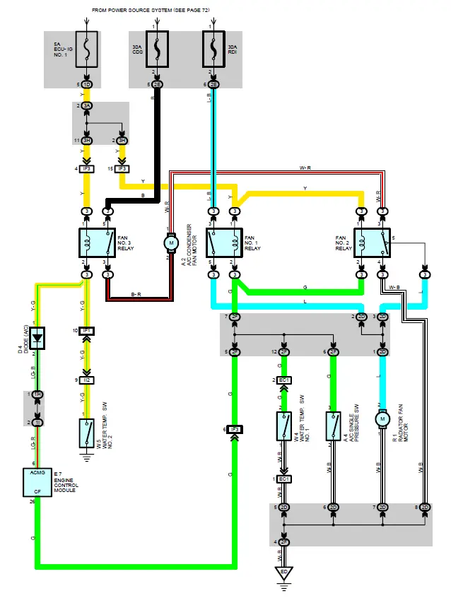
RADIATOR FAN AND CONDENSER FAN
SYSTEM OUTLINE
The radiator fan motor and A/C condenser fan motor operates according to the water temp. SW NO.1, water temp. SWV NO.2, A/C single pressure SW, and the A/C system condition. The FAN NO.1 relay, FAN NO.2 relay, FAN NO.3 relay are turned on/off, to operate the fan motors at low speed (In series), or high speed (in parallel).
LOW-SPEED OPERATION
Either when the A/C system is operating, or when the water temp. SW NO.2 is on, the radiator fan motor and A/C condenser fan motor operates at low speed.
HIGH-SPEED OPERATION
Ether when the AC system is operating, or when the water temp. SW NO.2 is on, if the water temp. SW NO.1 or AC single pressure SW is on, the radiator fan motor and A/C condenser fan motor operates at high speed.
SERVICE HINTS
A3 A/C SINGLE PRESSURE Sw
- 3-2: Open above approx. 15.5 kgf/cm (224 psi, 1520 kpa
- Close below approx. 12.5 kgf/cm2 (181 psi, 1225 kpa)
PARTS LOCATION
| Code | See Page | Code | See Page | Code | See Page |
| A2 | 44 | D4 | 48 (Floor Shift) | R1 | 45 |
| A4 | 44 | E7 | 46 (Column Shift) | W4 | 45 |
| D4 | 46 (Column Shift) | 48 (Floor Shift) | W5 | 45 |
RELAY BLOCKS
| Code | See Page | Relay Blocks (Relay Block Location) |
| 3 | 24 | Engine Room R/B No.3 (Near the Radiator Fan) |
JUNCTION BLOCK AND WIRE HARNESS
| Code | See Page | Junction Block and Wire Harness (Connector Location) |
| 1D | 27 | Cowl Wire and Driver Side J/B (Lower Finish Panel) |
| 1H | 27 | Engine Room Main Wire and Driver Side J/B (Lower Finish Panel) |
| 1I | 27 | Cowl Wire and Driver Side J/B (Lower Finish Panel) |
| 2D | 30 | Engine Room Main Wire and Engine Room J/B (Engine Compartment Left) |
| 2E | ||
| 2F | ||
| 3A | 34 | Cowl Wire and J/B No.3 (Left Kick Panel) |
| 3H | 35 |
CONNECTOR JOINING WIRE HARNESS AND WIR
| Code | See Page | Joining Wire Harness and Wire Harness (Connector Location) |
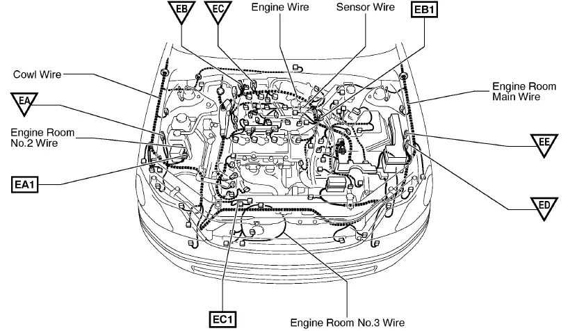
| EC1 | 54 | Engine Room Main Wire and Engine Room No.3 Wire (Near the Radiator Fan) |
| IF1 | 56 (Column Shift) |
Engine Room Main Wire and Cowl Wire (Left Side of Instrument Panel) |
| 60 (Floor Shift) | ||
| IF3 | 56 (Column Shift) | |
| 60 (Floor Shift) | ||
| II2 | 58 (Column Shift) | Engine Wire and Cowl Wire (Behind the Glove Box) |
| 62 (Floor Shift) |
GROUND POINTS
| Code | See Page | Ground Points Location |
| ED | 54 | Front Side of Left Fender |
TROUBLESHOOTING
VOLTAGE CHECK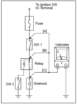
- Establish conditions in which voltage is present at the check point.
Example:- Ignition SW on
- Ignition SW and SW 1 on
- Ignition SW, SW 1 and Relay on (SW 2 off)
- Using a voltmeter, connect the negative lead to a good ground point or negative battery terminal, and the positive lead to the connector or component terminal. This check can be done with a test light instead of a voltmeter.
CONTINUITY AND RESISTANCE CHECK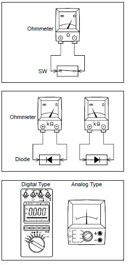
- Disconnect the battery terminal or wire so there is no voltage between the check points.
- Contact the two leads of an ohmmeter to each of the check points.
If the circuit has diodes, reverse the two leads and check again. When contacting the negative lead to the diode positive side and the positive lead to the negative side, there should be continuity. When contacting the two leads in reverse, there should be no continuity.
- Use a volt/ohmmeter with high impedance (10 kΩ/V minimum) for troubleshooting of the electrical circuit.
Push the terminal retainer down to the temporary lock position.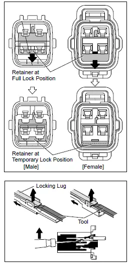
- Release the locking lug from terminal and pull the terminal out from rear.
INSTALL TERMINAL TO CONNECTOR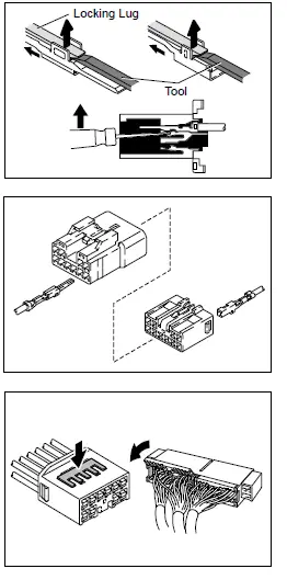
- Insert the terminal.
HINT:
- Make sure the terminal is positioned correctly.
- Insert the terminal until the locking lug locks firmly.
- Insert the terminal with terminal retainer in the temporary lock position.
2001 AVALON (EWD431U)


