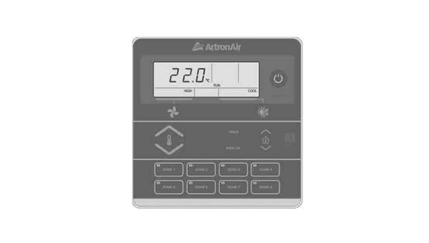
ActronAir LM7-2W Wall Controller Instruction Manual
Safety Precautions
- Read all instructions in this manual before operating the air conditioning unit. Failure to do so may result in damage to the unit and void your warranty.
- Turn-Off the power supply to the unit and follow necessary Lock Out & Tag Out procedures to ensure that power supply is not re-energised accidentally.
- This control interface is connected to the wall controller terminal block on the Indoor board via screwed terminals and 4 Core 14/0.20 0.44 mm Shielded Data Cable, with nominal voltage of 12VDC to 20VDC.
- Make sure that the unit installation complies with all relevant council regulations and building code standards. All electrical wiring must be in accordance with current electrical authority regulations and all wiring connections to be as per electrical diagram provided.
- WH&S rules and regulations must be observed and will take precedence during installation process.
- Only use this Control Interface with an ActronAir air conditioner as described in this installation guide.
Specifications
- Voltage: 12VDC to 20VDC
- Operating conditions: -10 to 60OC, < 90% RH non-condensing
- Storage conditions: -20 to 70OC, < 90% RH non-condensing
- Data: 4 Core 14/0.20 0.44 mm Shielded Data Cable
- Dimensions – mm: 130 x 130 x 14.5 (W x H x D)
Installation
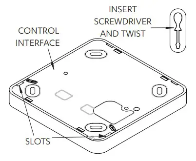
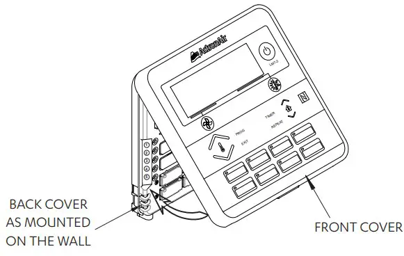
Remove front cover, as shown in the diagram below
- Insert and gently twist screwdriver into the slot at the side of the Control Interface. Do this procedure alternately between the two slots until the front of the control separates from the back cover.
- Use large enough flat blade screwdriver to fit into the slot in order to avoid damaging the Control Interface.

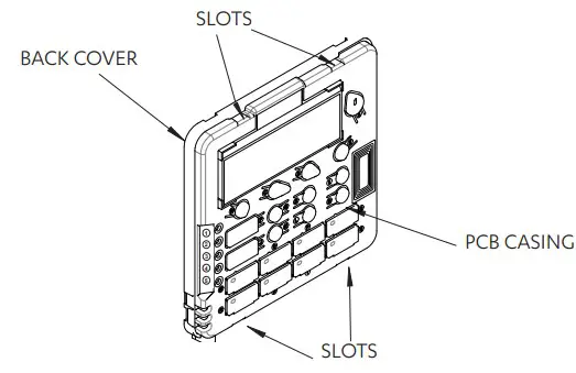
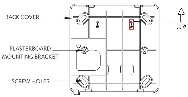
Remove back cover, as shown in the diagram below
- Insert and gently twist screwdriver into the slot at the top and the bottom of the Control Interface. Do this procedure alternately between the four slots until the back cover of the control separates.
- Use large enough flat blade screwdriver to fit into the slot in order to avoid damaging the Control Interface.

Mount back cover to the wall
- Mount the back cover to the wall with screws via screw holes. If required, the use of a plasterboard mounting bracket is recommended to mount the back cover to the wall.
- Ensure that the Control Interface back cover is aligned and leveled on the wall before tightening the screws

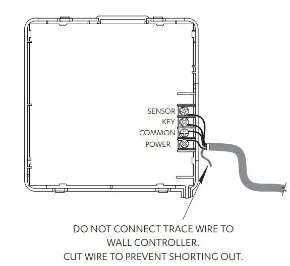
Connect wiring at the back of Control Interface
- Ensure that all wiring is tightly connected. All wiring must be in accordance with the provided wiring diagram.
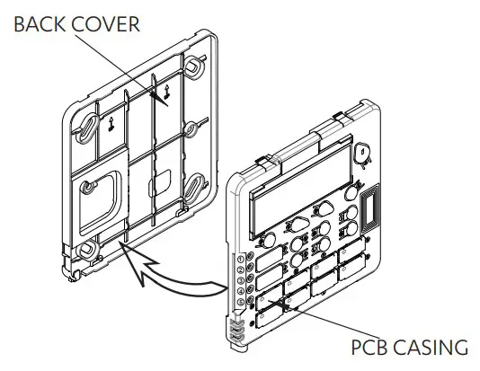
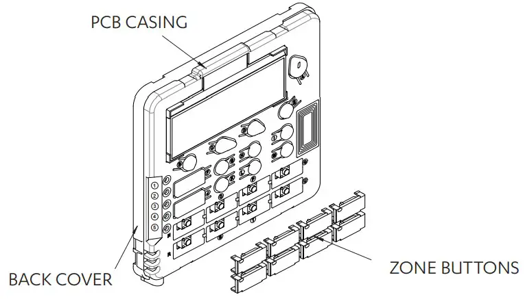
Attach PCB casing to the back cover
- Attach the PCB casing by aligning with the back cover mounted on the wall.
- Ensure the PCB casing makes a ‘click’ sound after mounting.

Select zone buttons
- Remove the relevant zone buttons for zone name to be allocated

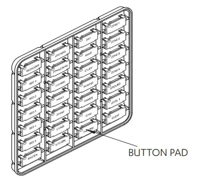
Assign and attach zones
- Attach the desired zone buttons and assign names to each zone.
- Ensure the buttons make a ‘click’ sound when attached to the PCB casing.

NOTE
Front cover can be removed even after installation. Press at the bottom of the control interface and pull the front cover.
Attach the front cover, as shown in the diagram below
IMPORTANT
Ensure protective film is removed from inside of the front cover before attaching.
- On completion of the mounting installation, check that the Control Interface is aligned and leveled on the wall.

Wiring Diagram
SRV Models
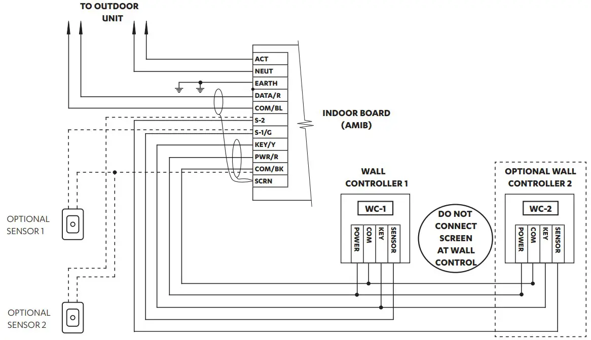
NOTE
- When using 2 wall controls, the second wall control’s onboard sensor must be wired from the indoor board and cannot be looped from the other wall control’s sensor terminal.
- Use only one 7-day controller with dual (MIMIC LOGIC) controller set up.
SRM Models
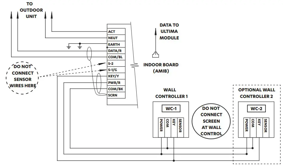
NOTE
Use only one 7-day controller with dual (MIMIC LOGIC) controller set up
Enabling / Disabling Zones and Assigning Sensors
NOTE
Check that the controller is turned OFF.
- Press and hold the “
 “ Button, press and release the “TIMER” Button and then release the “ “ Button.
 - Press the “
 ” Button repeatedly until “2-1” appears on the display screen.
NOTE
Zone 1 and 2 are always enabled and cannot be disabled. - Press the relevant zone button and the display will change to show the number of zones enabled.
For example: “2-1“ = 2 zones enabled
“3-1“ = 3 zones enabled - Press the “
 ” or “
  ” Button and select either Sensor 1 or 2 to assign sensors. For example: “2-1“ = 2 zones enabled, sensor 1 assigned to zone 2
“3-2“ = 3 zones enabled, sensor 2 assigned to zone 3
Select relevant zone button and follow step 4 to assign sensors. - Press the “ ” Button until the Main Screen appears.
 “ Button, press and release the “TIMER” Button and then release the “
 NOTE
Before returning to the Main Screen, ensure that the display screen is showing the correct number of zones that are required to be activated.
For example: “8-1“ upon exit = Zone 1 to Zone 8 are enabled
“5-1“ upon exit = Zone 1 to Zone 5 are enabled
“4-1” upon exit = Zone 1 to Zone 4 are enabled
Enabling / Disabling Last Zone (Safety Feature)
- Press “ ” Button to turn off air conditioner.
- Press and hold the Zone 1 Button, press and release the “ ” Button and then release Zone 1 Button. Display screen will show “1on”, signaling that 1 zone must remain ON (Factory Default Setting).
- Press the “ ” Button to turn off all zones. Display screen will show “1oF” (Suits homes with large common zones application).
- Press the “ ” Button to return to Main Screen.
- Repeat steps 1-4 to go back to Factory Default Setting.
 ” Button to turn off air conditioner.
 ” Button to turn off all zones. Display screen will show “1oF” (Suits homes with large common zones application).
THIS PAGE WAS INTENTIONALLY LEFT BLANK


