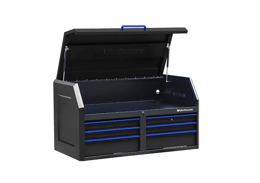
Montezuma M462406CH 6-Drawer Black Steel Lockable Tool Box Owner’s Manual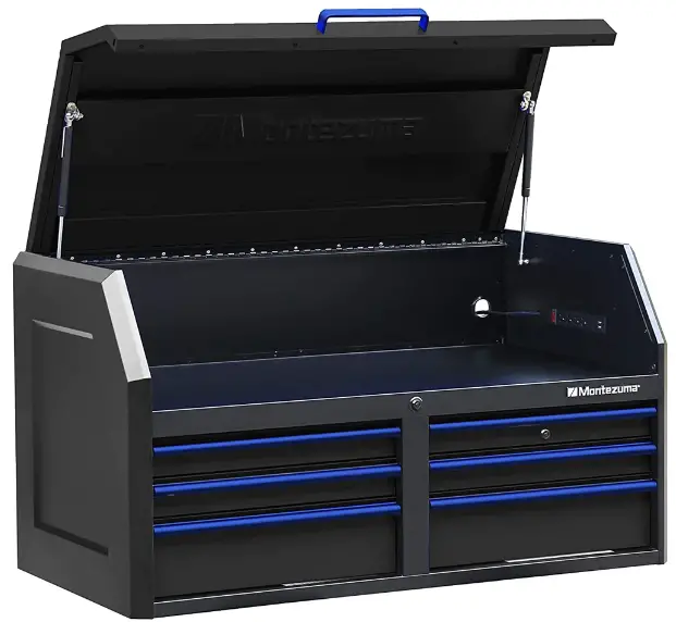
Introduction
Montezuma is committed to helping you succeed in both your work and personal life by being organized, prepared and equipped with the right tools, gear and home supplies at your finger tips.
We are here to ensure that your life is organized.
Thank you for your purchase of this Montezuma Tool Chest and Cabinet.
ATTENTION
TO REDUCE THE RISK OF INJURY, THE USER MUST READ AND UNDERSTAND THIS INSTRUCTION MANUAL BEFORE USING THIS PRODUCT FOR THE FIRST TIME. SAVE THESE INSTRUCTIONS FOR FUTURE REFERENCE
SPECIFICATIONS
MAXIMUM PRODUCT WEIGHT (INCLUDING CONTENTS): 2,100 lb (952 kg) MAXIMUM DRAWER WEIGHT: 150 lb (68 kg).
POWER STRIP
- MODEL: LTS-04C/CH-04F
- SURGE PROTECTIVE DEVICES
- RATING: 120 V AC 15 A 60 Hz 1875 W
- USB: TOTAL 2.1 A – Check your device for compatibility
- USB O/P: IT EQUIPMENT ONLY
- VPR: 500-1000 V (L-N) TYPE 3 SPD
- CONFORMS TO UL STD. NO 1363 AND ANSI/UL STD. NO. 1449
- CERTIFIED TO CSA STD. C22.2 NO. 308&8

46″ x 24″ 6-DRAWER TOOL CHEST
OVERALL DIMENSIONS:
- 46″ W x 24-5/8″ D x 25″ H (117 cm W x 62.5 cm D x 63.5 cm H)
- NET WEIGHT: 174.16 lb (79 kg)

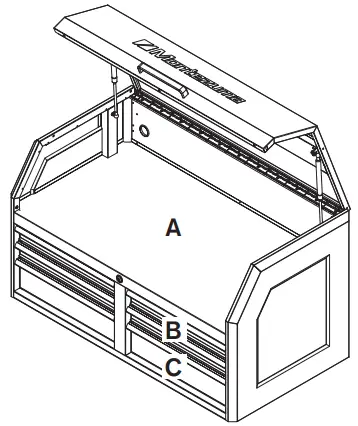
INSIDE TILL/DRAWER DIMENSIONS:
| REF | DIMENSIONS | QTY |
| A | 43″ W x 23-3/8″ D x 8-1/2″ H (109.3 cm W x 59.4 cm D x 21.7 cm H) | 1 |
| B | 19-1/4″ W x 21-1/8″ D x 2-3/8″ H (48.9 cm W x 53.8 cm D x 5.9 cm H) | 4 |
| C | 19-1/4″ W x 21-1/8″ D x 5-1/4″ H (48.9 cm W x 53.8 cm D x 13.4 cm H) | 2 |
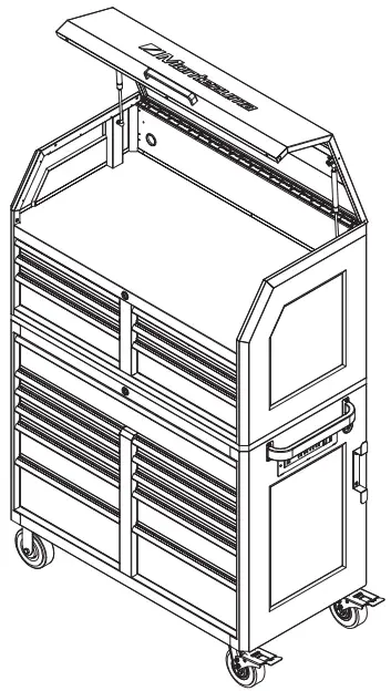
46″ x 24″ 11-DRAWER TOOL CABINET
OVERALL DIMENSIONS:
- 46″ W x 24-5/8″ D x 41-1/8″ H (117 cm W x 62.5 cm D x 104.5 cm H)
- NET WEIGHT: 330.69 lb (150 kg)

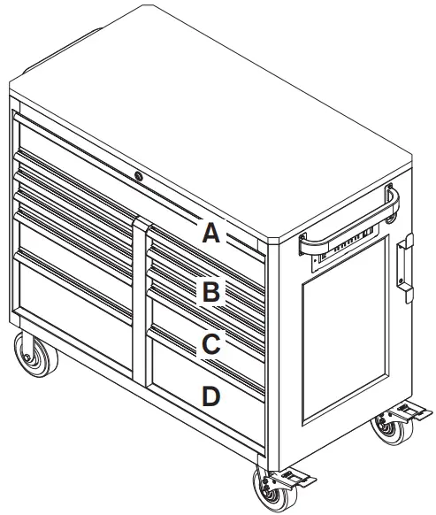
INSIDE DRAWER DIMENSIONS:
| REF | DIMENSIONS | QTY |
| A | 41-7/8″ W x 21-1/8″ D x 5-1/4″ H (106.5 cm W x 53.8 cm D x 13.4 cm H) | 1 |
| B | 19-1/4″ W x 21-1/8″ D x 2-3/8″ H (48.9 cm W x 53.8 cm D x 5.9 cm H) | 6 |
| C | 19-1/4″ W x 21-1/8″ D x 5-1/4″ H (48.9 cm W x 53.8 cm D x 13.4 cm H) | 2 |
| D | 19-1/4″ W x 21-1/8″ D x 8-1/4″ H (48.9 cm W x 53.8 cm D x 20.9 cm H) | 2 |
* Dimensions do not include side handles.
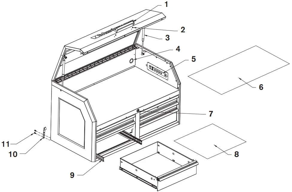
CHEST PARTS LIST
| REF DESCRIPTION | PART NUMBER | QTY | |
| 1 | Chest Handle | 301883 | 1 |
| 2 | M4 x 12 mm Phillips Head Bolt | 320084 | 2 |
| 3 | Gas Strut | 303187 | 2 |
| 4 | Grommet | 314027 | 2 |
| 5 | Power Strip | 333059 | 1 |
| 6 | Till Liner | 552092 | 1 |
| 7 | Lock and Key (1201-1204) | 304166 | 2 |
| 8 | Drawer Liner | 551891 | 6 |
| 9 | Slide Set | 300380-300381 | 6 |
| 10 | Connector | 240091 | 2 |
| 11 | M6 x 12 mm Hex Bolt | 321051 | 4 |
The keys are taped to the top storage area of the chest.
To order replacement parts, email [email protected] or call 1-800-459-4409 (Monday–Friday, 8:00 am–4:30 pm, CST). Have the part number and quantity ready.
Replacement keys may be ordered using the code that appears on the face of the lock.
Not all parts are covered under warranty. Those parts not covered can be purchased.
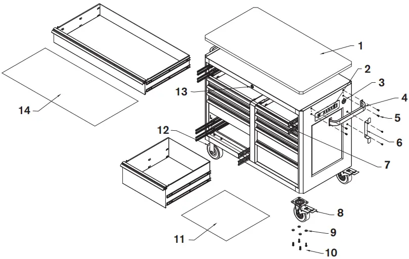
CABINET PARTS LIST
| REF DESCRIPTION | PART NUMBER | QTY | |
| 1 | Work Top | 572015 | 1 |
| 2 | Power Strip | 333059 | 1 |
| 3 | Grommet | 314027 | 1 |
| 4 | Cabinet Handle | 306142 | 2 |
| 5 | M6 x 12 mm Phillips Head Bolt | 320323 | 10 |
| 6 | Cord Wrap | 236870 | 1 |
| 7 | Slide Set | 300380-300381 | 14 |
| 8 | Swivel Caster | 302231 | 2 |
| 9 | Washer | 324002 | 16 |
| 10 | M8 x 25 mm Hex Bolt | 321047 | 16 |
| 11 | Drawer Liner | 551891 | 10 |
| 12 | Rigid Caster | 302232 | 2 |
| 13 | Lock and Key (1201-1204) | 304166 | 1 |
| 14 | Drawer Liner | 551892 | 1 |
They keys are taped to he top of the caster carton, which is placed in the bottom right drawer of the cabinet.
To order replacement parts, email [email protected] or call 1-800-459-4409 (Monday–Friday, 8:00 am–4:30 pm, CST). Have the part number and quantity ready.
Replacement keys may be ordered using the code that appears on the face of the lock.
Not all parts are covered under warranty. Those parts not covered can be purchased.
HANDLE INSTALLATION
NOTE: Assemble the handles first to make it easier to move the cabinet.
Position the handles over the holes in the cabinet and attach with the M6 x 12 mm Phillips head bolts provided.
Tighten securely using a 10 mm socket.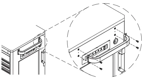
CASTER INSTALLATION
CAUTION: Two or more people are required to lay down or stand up the cabinet. Use the side handles for assistance. DO NOT stand in front of or behind the product during this process. Lock drawers before proceeding.
Carefully lay the cabinet on its back, with a soft mat underneath for protection.
Position the two swivel casters on the cabinet bottom, on either the left or right side.
Insert four M8 x 25 mm hex bolts through washers, then through each caster and into the bottom of the cabinet.
Tighten securely using a 14 mm socket.
Repeat for the two rigid casters on the other side of the cabinet.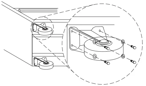
CORD WRAP INSTALLATION
Position the cord wrap over the holes in the cabinet. Attach with the M6 x 12 mm Phillips head bolts provided. Tighten securely.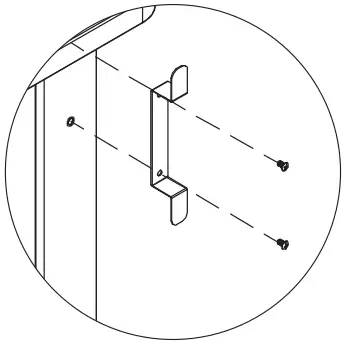
POWER STRIP INSTALLATION
Cut the black strip holding the cord, then pull the white strip to get the plug out of the cabinet and through the grommet. Tighten the grommet.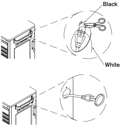
CHEST AND CABINET CONNECTION
CAUTION: Two or more people may be required to complete this step.
NOTE: It is not required to remove the worktop attached to the cabinet. If you do want remove the worktop, first remove the drawers, then unbolt the worktop.
Place the chest on the cabinet. Attach the connectors to the chest, making sure the hook head snaps in the square hole on the back of the chest. Fasten the M6 x 12 mm hex bolts to the cabinet.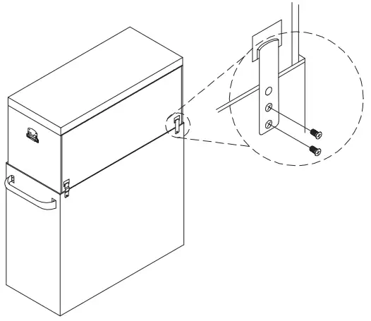
RAISE AND RELEASE DRAWER FRONTS
These units are equipped with raise and release drawer fronts. To open, lift up on the drawer front while pulling towards you. To close, shut the drawer firmly until the latch engages.
If the drawer does not stay closed, the hook may be bent, or it may be rubbing against the drawer slides. To fix this problem, lightly bend the hook until the drawer will engage in the slide.
DRAWER REMOVAL
Pull the drawer out so that it’s almost fully extended. Push up on the black release lever on one side, while pushing down on the black release lever on the other side. While holding the levers in these positions, pull the drawer outward until it is released from the drawer slide.
ONE SIDE – PUSH UP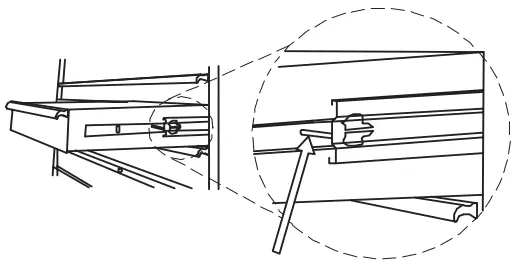
OTHER SIDE – PUSH DOWN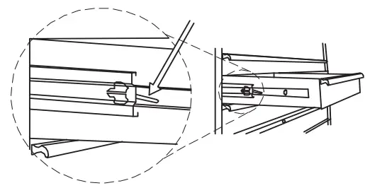
DRAWER REPLACEMENT
Extend the drawer slides from the unit. Insert the brackets on each side of the drawer into the slots in the slides, being careful that they are properly positioned. Once properly inserted, completely close the drawer to set the slides in position.
MAINTENANCE
Periodically clean the drawer fronts, trim, and other surfaces with mild detergent and water.
Lubricate the casters with high quality bearing grease (annually/yearly).
Lubricate the slides (twice a year) with a product like WD40 or other quality lubricant. This is especially important in low temperatures, which can cause the bearing to become stiff.
Grease and oil can be removed with most standard cleaning fluids. For safety, use a nonflammable cleaning fluid.
SAFETY
- RISK OF ELECTRIC SHOCK. To reduce the risk of electric shock, use indoors in a dry location only. Do not plug the power strip into another power strip. Not for use for a permanent installation.
- Changes or modifications to this unit not expressly approved by the party responsible for compliance could void the user’s authority to operate the equipment.
- Close the cover and lock the drawers before moving this product. The drawers could come open and make the product unstable and tip, which may cause personal injury or product damage.
- Do not attempt to lift the unit by its side handles using chains, ropes or other lifting devices. The side handle could fail, which may cause personal injury or damage to the product.
- DO NOT stand on this product or lean on the drawers or work surface.
- WEAR SAFETY GLASSES when removing or repositioning the slides. The tool could slip, which may cause personal injury.
- When moving this product, do not pull it. Push the product to prevent personal injury.
- USE THE BRAKES when not moving this product. This will prevent the product from rolling, which may cause personal injury or product damage.
- BE CAREFUL when opening more than one drawer. The product could become unstable and tip, which may cause personal injury or product damage.
- DO NOT mount this product on a truck bed or any other moving object. This may cause personal injury or product damage, and will void the warranty. Secure this product properly before moving it with a forklift.
- DO NOT tow with power equipment. The product could tip, which may cause personal injury or product damage.
- Keep the product on level surfaces. The product could become unstable and tip if stored or moved on an uneven surface, which may cause personal injury or product damage.
Warranty

This product is warranted to be free from defects in materials and workmanship for a period of five (5) years from the date of original purchase.
If this product is defective, email [email protected] or call 1-800-459-4409 (Monday–Friday, 8:00 am–4:30 pm, CST). If the product is defective, we will replace the defective part at no cost to you.
Please do not ship your product back to the store or to us unless we send you written instructions for return.
In the event it becomes necessary for your product to be returned, we will notify you how to proceed.
A copy of your original purchase receipt must accompany the returned product.
![]() WARNING
WARNING
Cancer and Reproductive Harm – www.P65Warnings.ca.gov
Customer Support
Manufactured by:
QUALITY CRAFT
Romeoville, IL, USA 60446
[email protected]
1-800-459-4409
(Monday to Friday, 8:00 am–4:30 pm, CST)
Made in China
www.montezumastorage.com