![]()
ZGP486NDTSS Gas Professional Range
PROPANE CONVERSION INSTRUCTIONS![]() WARNING
WARNING![]()
Explosion Hazard
Death or serious injury can result from failure to follow these instructions.
- Service by a qualified service technician only.
- Shut off the gas supply and disconnect the power before servicing.
- Reconnect all grounding devices after service.
- Replace all parts and panels before operating.
The pressure regulator and the burner orifices are set for natural gas. To use propane gas, the regulator and burner orifices must be converted. This product cannot be converted to propane by adjusting the oven orifices. The orifices must be replaced with propane. abhmahbladance Do not operate the cooktop or oven burners of this range when using propane (bottled) gas before converting the pressure regulator and burner orifices for propane gas use. Failure to do so could cause high flames and toxic fumes which can result in serious injury.
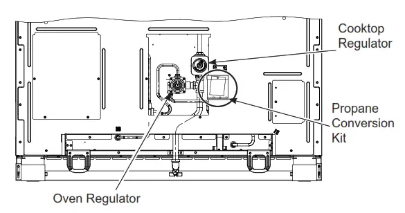
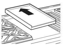
The propane orifices for the cooktop burners are shipped on the back of the range in the location shown.
TOOLS REQUIRED:
- Adjustable wrench
- Nut drivers: 114″, 9/32″
- Socket wrench with or 7mm 1/2″ socket and extension
- 7mm open-end wrench
- Phillips head screwdriver
- Phillips screwdriver
- Flat-bladed screwdriver (blade
- Large flat blade screwdriver approximately 3/32″ across)
To adjust your range for use with propane gas, follow these instructions:
- Disconnect all electrical power, at the main circuit breaker or fuse box. 2. Shut off the gas supply to the range by closing the manual shut-off valve.
CONVERTING THE PRESSURE REGULATORS
 If gas is detected at the regulator, use a liquid leak detector to verify the location.
Oven Regulator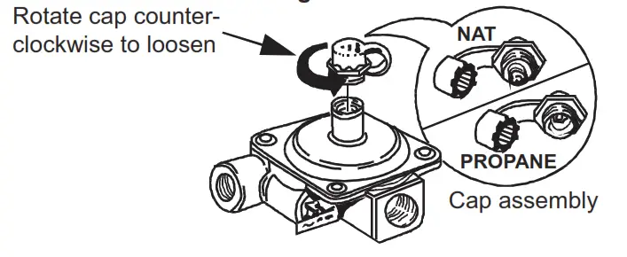
- Use an adjustable wrench to unscrew the hex-nut cap from the pressure regulator.
- Completely remove the protective plastic cap off the threaded metal cap.
- Turn the metal cap so the type of gas being converted to is displayed and replace the protective plastic cover.
- Screw the hex-nut cap back into the regulator.
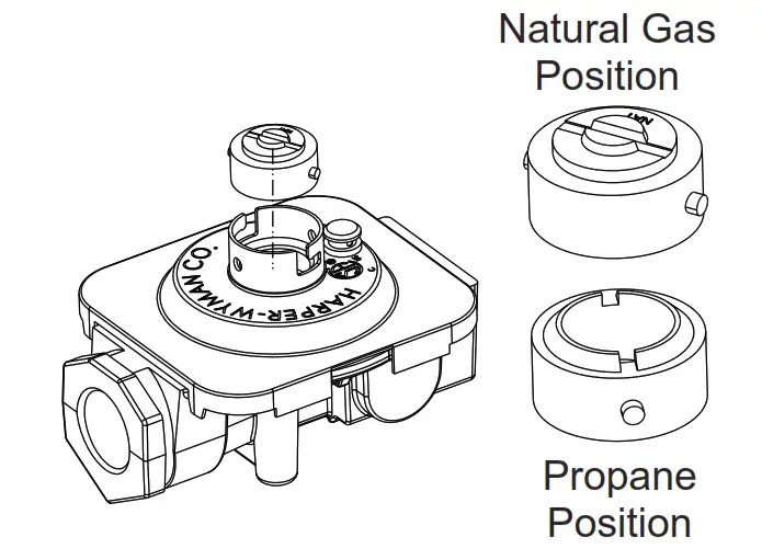
(Do not over-tighten) Cooktop Regulator
- Use a large flat-blade screwdriver to remove the cap from the pressure regulator.
- Turn the brass cap over for propane gas and reinstall the regulator.
CONVERTING THE COOKTOP BURNERS
A. Remove the top grates, burner caps, and burner heads.
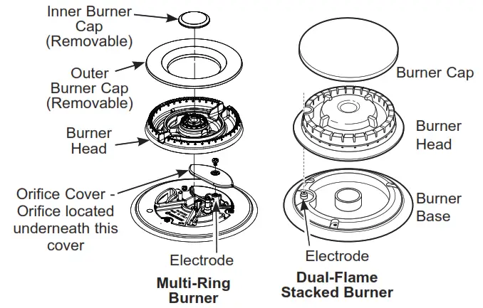 B. Use a 7 mm or 9/32” nut driver for the Dual Stack burner, or a 7mm or 9/32” open-end wrench (only for Multi-ring) to remove the top burner orifices. These may be accessed through the burner opening in the base. The Multi-Ring orifice is accessed by removing the orifice cover using a Phillips screwdriver.
NOTICE: Save these orifices for future conversion back to natural gas.
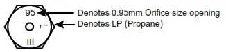
C. Remove the propane orifices from the bag provided.
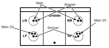
 ZGP304
ZDP304
| BURNER OUTPUT RATINGS: BTU/HR | |||
| Propane Gas 10” W.C.P. | |||
| BURNER | BTU RATE | ORIFICE SIZE | MARKING |
| LF | 21,000 | ||
| Simmer | 0.52 mm | 52SL | |
| Main 2X | 0.88 mm | 88XL | |
| RF | 15,000 | ||
| Simmer | 0.34 PP | 346/ | |
| Main | 1.08 mm | 108L | |
| LR, RR | 12,000 | ||
| Simmer | 0.34 PP | 346/ | |
| Main | 0.95 mm | 95XL | |
| Broil (=*3304 RQO\) | 18,000 | 0.048´ | 48/ |
| %DNH (=*3304 RQO\) | 21,500 | 0.053” | 53L |
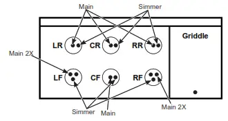
 ZGP366
ZDP366
| BURNER OUTPUT RATINGS: BTU/HR | |||
| Propane Gas 10” W.C.P. | |||
| BURNER | BTU RATE | ORIFICE SIZE | MARKING |
| LF, RF | 21,000 | ||
| Simmer | 0.52 mm | 52SL | |
| Main 2X | 0.88 mm | 88XL | |
| CF, CR | 10,000 | ||
| Simmer | 0.34 PP | 346/ | |
| Main | 0.88 mm | 88XL | |
| LR, RR | 15,000 | ||
| Simmer | 0.34 PP | 346/ | |
| Main | 1.08 mm | 108L | |
| Broil (=*3366 RQO\) | 18,000 | 0.048´ | 48/ |
| %DNH (=*3366 RQO\) | 21,500 | 0.053” | 53L |
ZDP364
| BURNER OUTPUT RATINGS: BTU/HR | |||
| Propane Gas 10” W.C.P. | |||
| BURNER | BTU RATE | ORIFICE SIZE | MARKING |
| LF, RF | 21,000 | ||
| Simmer | 0.52 mm | 52SL | |
| Main 2X | 0.88 mm | 88XL | |
| LR, RR | 12,000 | ||
| Simmer | 0.34 PP | 346/ | |
| Main | 0.95 mm | 95XL | |
| Griddle | 16,000 | 0.047´ | 047 |
| Broil | 18,000 | 0.048´ | 48/ |
| %DNH | 21,500 | 0.053” | 53L |
 ZGP486
ZDP486
| BURNER | OUTPUT RATINGS: BTU/HR | |||
| Propane Gas 10″ BTU RATE | W.C.P. | MARKING | ||
| ORIFICE SIZE | ||||
| BURNER | ||||
| LF, RF | 21,000 | |||
| Simmer | 0.52 mm | 52SL | ||
| Main 2X | 0.88 mm | 88XL | ||
| CF, CR | 10,000 | |||
| Simmer | 0.34 mm | 34SL | ||
| Main | 0.88 mm | 88L | ||
| LR, RR | 15,000 | |||
| Simmer | 0.34 mm | 34SL | ||
| Main | 1.08 mm | 108L | ||
| Griddle | 16,000 | 0.047″ | 47 | |
| Left Oven (ZGP486 only) | Broil | 11,000 | 0.038″ | 38L |
| Bake | 10,000 | 0.037″ | 37L | |
| Right Oven (ZGP486only) | Broil | 18,000 | 0.048″ | 48L |
| Bake | 21,500 | 0.053″ | 53L | |
ZDP484
| BURNER OUTPUT RATINGS: BTU/HR Propane Gas 10” W.C.P. | |||
| BURNER | BTU RATE | ORIFICE SIZE | MARKING |
| LF, RF | 21,000 | ||
| Simmer | 0.52 mm | 52SL | |
| Main 2X | 0.88 mm | 88XL | |
| LR, RR Simmer Main | 12,000 0.34 PP 0.95 mm | 346/ 95XL | |
| Griddle | 16,000 | 0.047´ | 047 |
| Grill | 14,000 | 0.047´ | 047 |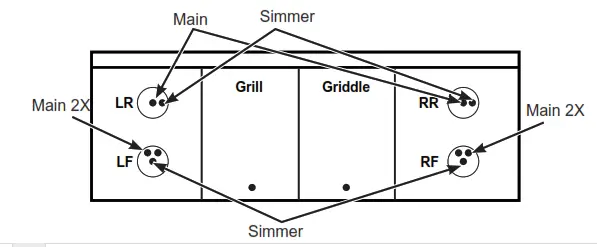
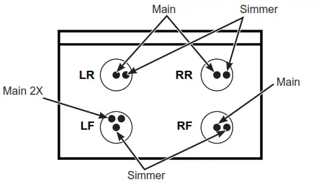
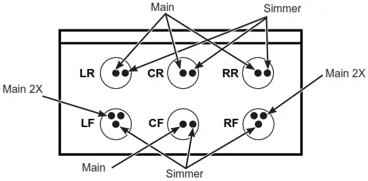
 D.Install the propane orifices in their precise locations. To prevent leakage, make sure the orifice spuds are securely hand-tightened into the gas supply tubes. The orifice cover must be reinstalled.
E. Install the old orifice spuds into the bag along with these instructions, and replace them onto the back of the range for possible future conversion.
CONVERT GRIDDLE ORIFICE
Locate the 3/4″ long griddle orifice. Select the proper orifice size for your gas and burner from the conversion chart. A. Lift off the griddle flue cover. Remove the 2 inside clamping screws.
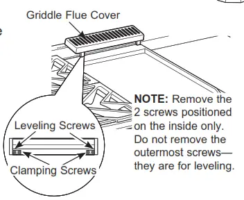
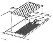
B. Lift out the cast-iron grease trough.
Remove by sliding the griddle toward the rear and out of the hold-down tabs along the bottom.
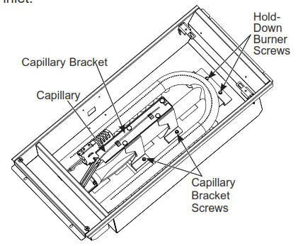
 C. Remove the 4 screws on the capillary bracket and set the bracket and capillary aside.
D. Remove the 2 hold-down screws at the rear of the burner. Pull the burner straight back toward the rear and out of the gas inlet.
 E. Use a 1/2” deep well socket to remove and replace the orifice.
Reverse these steps to reassemble the griddle. Push excess capillary back into the entry hole. Place the unused orifice in the holder for possible future use.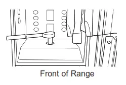
CONVERT GRILL ORIFICE
Locate the 3/4” long Grill orifice. Select the proper orifice size for your gas and burner from the conversion chart.
A. Remove the grill cover, grates, and grate frame. Lift the radiant baffle straight up and off.
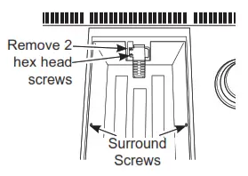
 B. Remove the 2 hex head screws from the top of the igniter.
Remove one screw from each side of the burner surround.
Lift out the surround.
 C. Carefully push the igniter aside and under the burner.
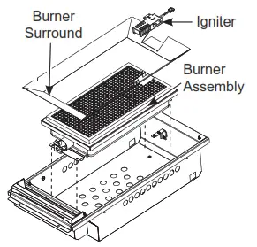
Do not pull or pinch the wire.
Remove 4 burner attachment screws, 2 at the front and 2 at the back. Slide the burner assembly toward the back and out of the gas inlet.
D. Use a 1/2” deep well socket to remove and replace the orifice.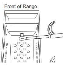 Reverse these steps to re-assemble the grill. Be sure to place the unused orifice in the holder for possible future use.
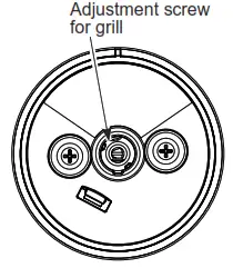
E. Adjust Grill “LO” Setting a Make certain gas and electricity to the unit are turned off.
- Turn the grill knob to LO and remove the knob by pulling it straight off.
- Insert a small flat-blade screwdriver into the hole in the center of the valve stem to engage set screw.
- To convert the LO setting from natural gas to propane (LP), turn the screw clockwise until it stops (about 1-3/4 turn). It may be necessary to grasp the exterior of the valve stem with a pair of pliers to prevent the valve stem from rotating as the set screw is adjusted.
- To convert the LO setting from the propane (LP) to the natural gas sets, turn the screw counterclockwise about 1-3/4 tum.
 Locate the 3/4″ long bake burner orifice.
Select the proper orifice size for your gas and burner from the conversion chart.
A. Remove the oven door and set it aside in a safe location. Refer to Installation Instructions.
B. Remove the 2 oven bottom hold-down screws from the rear of the Denver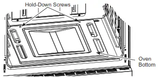 C. Slide the oven bottom forward and set aside.
D. Remove the burner screw.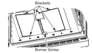 E. Lift the front of the burner up slightly and slide forward setting aside (careful not to damage the igniter.)
F. Use a 1/2″ deep well socket to remove and replace the orifice.
G. Adjust the shutter setting per the chart.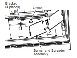 H. Reverse these steps to reassemble the aven. vote oven parts. Make sure you replace one ede uatniy was – 4 bracket tabs. Place the unused orifice if-the holder for= => 5:2 possible future use.
CONVERT LEFT BAKE BURNER ORIFICE (on 48” models only)
Locate the 3/4″ long bake burner orifice.
Select the proper orifice size for your gas and burner from the conversion chart.
A. Remove the oven door and set it aside in a safe location.
B. Remove the 2 oven bottom hold-down screws from the tear of the cover.
 C. Slide the oven bottom forward and set aside.
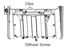 D. Remove the burner diffuser screw.
E. Lift the front of the bumper diffuser up slightly and slide it forward to disengage the clips at the rear. Set the bumper diffuser aside.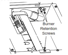
F. Remove the 3 bummer retention screws (1 in front and 2 at the rear)
G. Lift the front of the burner up slightly and slide leftward to remove.
H. Use a 1/2″ deep well socket to remove and replace the orifice.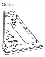 Reverse these steps to reassemble the oven burner and oven parts. Place the unused orifice in the holder for possible future use.
CONVERT LEFT BROIL BURNER ORIFICE (on 48” models only)
A. Remove the oven door and set it aside ina safe location.
B. Remove the 4 Electric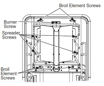 Element screws.
C. Pull electric elements out until terminals reach the hole (do not disconnect terminals) and carefully place the element over the oven floor.
D. Remove the 4 Spreader screws (refer to picture 1).
E. Remove the Bummer screw and then carefully set the broil system aside (refer to picture 1).
 F. Use a %” socket wrench to loosen and remove and replace the broil orifice.
G. Adjust the shutter setting per the chart.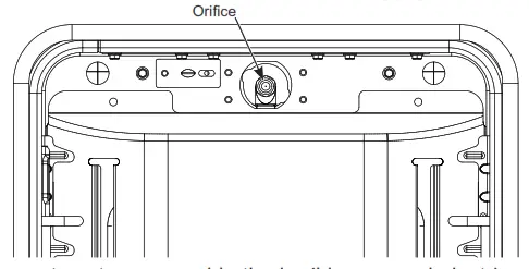
H. Revere steps to reassemble the broil burner and electric element. Place the unused orifice in the holder for possible future use.
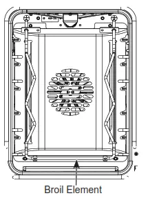
CONVERT BROIL BURNER ORIFICE
Locate the broil burner orifice.
Select the proper orifice size for your gas and burner from the conversion chart.
A. Remove the oven door and set aside in a safe location.
B. Remove the 4 Electric Element screws.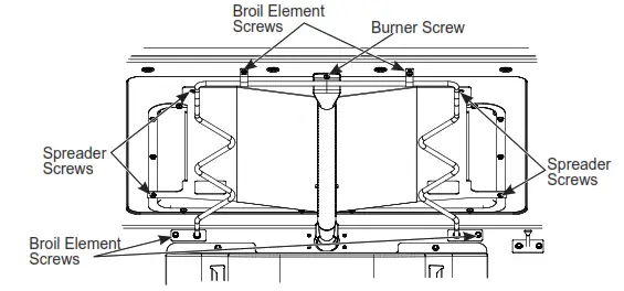
C. Pull electric elements out until terminals reach the hole (do not disconnect terminals). The carefully lower front edge of the element to the oven floor.
D. Remove the 4 Spreader Screws.
E. Remove the Bummer Screw and then carefully set the broil system aside. 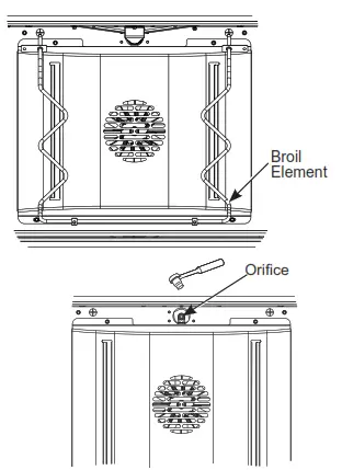 F. Use %” socket wrench to loosen, remove, and replace the broil orifice.
G. Adjust the shutter setting per the chart.
H. Reverse steps to reassemble the broil burner and electric element. Place the unused orifice in the holder for possible future use.
ADJUSTING AIR SHUTTER SETTINGS FOR OVEN BURNERS
The air shutters should be turned to the marked settings NG or propane or set according to the following table.
| BURNER | AIR SHUTTER SETTING FOR PROPANE | AIR SHUTTER SETTING FOR NG | |||
| Bake | 0.430″ | 0.355″ | |||
| Broil | 0.470″ | 0.470″ |
| OVEN | BURNER | AIR SHUTTER SETTING FOR PROPANE | AIR SHUTTER SETTING FOR NG | ||
| Left Oven (ZGP486 only) | Bake | 0.540″ | 0.250° | ||
| Broil | 0.410″ | 0.355″ | |||
| Right Oven (ZGP486 only) | Bake | 0.430″ | 0.355° | ||
| Broil | 0.470″ | 0.470″ | |||
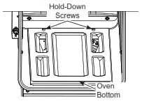
- With a Phillips head screwdriver, loosen the screws securing the air shutter on the bake burner. Adjust the air shutter to the dimension given in the above table.
- Turn on the gas.
- Turn on the electricity.
- Reinstall the oven door.
- Turn on the bake burner. The oven burner flame must be observed with the door closed to properly check flame characteristics.
- As you watch the flame with the oven door closed, check the following through the oven door window.
a. For Natural Gas, if the flames are yellow, open the air shutter more.
b. If the flames blow away or flutter from the burner, close the air shutter slightly. - Turn the bake bumper off and repeat with the broil burner.
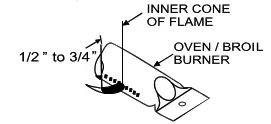
 WARNING If attempt to measure the inner cone of the flame, please use caution: burns could result.
 - Checking the flame size: It should be approximately 1/2” to 3/4” long for the bake and broil burners. The combustion quality of the burner flames needs to be determined visually.
 NOTE: If burner flames look like (A), further air shutter adjustment to the bake burner is required. Normal burner flames should look like (B) or (C), depending on the type of gas you use. With propane gas, some yellow tipping on the outer cones is normal. Foreign particles in the gas line may cause an orange flame at first, but this will soon disappear.
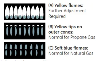
- When all adjustments are made and the results are satisfactory:
a. Retighten the air shutter screws.
b. Replace the oven bottom.
CHECK SURFACE BURNERS
Push and tum a knob to the LITE position. A clicking sound indicates the proper operation of the ignition system. When lighting any burner, sparks will appear at all burners but gas flows from only the one selected. Once air is purged from the supply line, the burner should light within 4 seconds. After the burner lights, rotate the knob out of the LITE position. Try each bummer in succession until all burners have been checked.
Quality of Flames
Determine the quality of flames visually. Normal burner flames should look like (A) or (B).
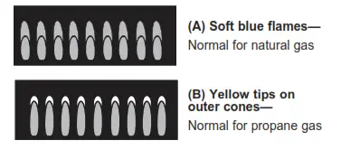 Long, bright yellow flames are not normal. Normal flames may show signs of an orange tint when well heated or signs of flickering orange due to particles in the gas or air.
ADJUSTING THE LOW FLAME SETTING ON COOKTOP BURNERS
Low-setting adjustments must be made with other bumpers in operation on a medium setting. This procedure prevents the low flame from being set too low, resulting in the flame being extinguished when other burners are turned on.
A. Turn on all surface burners to a medium setting.
B. Multi-Ring Burners — Outer Ring and Inner Ring
- Rotate the knob to the MED setting.
- Remove the knob and insert a small flat-blade screwdriver into the valve shaft and tum clockwise to tighten down the bypass set screw. Hold the outer shaft while turning inner screw.
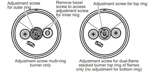
- The OUTER RING flames should be adjusted so that they barely curl over the top edge of the burner cap as shown
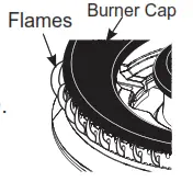
- If the flame appears too low or unstable, slowly turn the bypass screw counterclockwise until a stable flame exists for each burner. Remember, another burner must be turned on to MED.
- Replace the knob and rotate the knob to the LO setting.
- Remove the knob AND the right side bezel screw as shown.
- The INNER RING flames should be adjusted by inserting a small flat-blade screwdriver into the bezel screw hole and turning clockwise to tighten down the bypass set screw with the knob at the LO setting. Locate the screw through the hole with a flashlight if necessary.
- If the flame appears too low or unstable, slowly tug bypass the screw counterclockwise until a stable flame exists for each bummer. Remember, another burner must be turned on to MED. When adjusting, make sure the low flame is contacting the ignitor and the burner head is grounded properly or the spark module will continue to attempt to reignite the flame.
- Reinstall the right side bezel screw. Do not over-tighten.
Replace the knob.
C. Dual-Flame Stacked Burners — Upper Flames
- Rotate the knob to the MED setting.
- Remove the knob.
- The upper ring of flames should be adjusted with the knob at the MED setting by adjusting the set screw in the center valve shaft. Hold the outer shaft while turning the inner screw. The flames should be adjusted so that they barely curl over the top edge of the burner cap.
- Replace knob.
D. Additionally quickly open the oven door while observing the flame. If the flame is extinguished, continue adjusting the set screw for a larger flame. Repeat door openings until the flame is stable.
SPECIAL NOTE:
To convert the oven back to natural gas, reverse the Instructions given in making propane adjustments. Save these orifices for future conversion back to natural gas.
ADDITIONAL INFORMATION
ZGP304
ZDP304
| BURNER OUTPUT RATINGS: BTU/HR | |||
| NG (Natural) Gas 5” W.C.P. | |||
| BURNER | BTU RATE | ORIFICE SIZE | MARKING |
| LF | 21,000 | ||
| Simmer | 0.82 mm | 82SN | |
| Main 2X | 1.38 mm | 138XN | |
| RF | 15,000 | ||
| Simmer | 0.51 mm | 51SN | |
| Main | 1.68 mm | 168N | |
| LR, RR | 15,000 | ||
| Simmer | 0.51 mm | 51SN | |
| Main | 1.68 mm | 168N | |
| %URiO (=*3304 RQO\) | 18,000 | 0.074´ | 741 |
| %DNH (=*3304 RQO\) | 23,500 | 0.085” | 85N |
ZGP366
ZDP366
| BURNER OUTPUT RATINGS: BTU/HR | |||
| NG (Natural) Gas 5” W.C.P. | |||
| BURNER | BTU RATE | ORIFICE SIZE | MARKING |
| LF, RF | 23,000 | ||
| Simmer | 0.82 mm | 82SN | |
| Main 2X | 1.46 PP | 146;1 | |
| CF, CR | 15,000 | ||
| Simmer | 0.51 mm | 51SN | |
| Main | 1.68 mm | 168N | |
| LR, RR | 18,000 | ||
| Simmer | 0.51 mm | 51SN | |
| Main | 1.86 mm | 186N | |
| %URiO (=*3366 RQO\) | 18,000 | 0.074´ | 741 |
| %DNH (=*3366 RQO\) | 23,500 | 0.085” | 85N |
ZDP364
| BURNER OUTPUT RATINGS: BTU/HR | |||
| NG (Natural) Gas 5” W.C.P. | |||
| BURNER | BTU RATE | ORIFICE SIZE | MARKING |
| LF | 23,000 | ||
| Simmer | 0.82 mm | 82SN | |
| Main 2X | 1.46 PP | 146;1 | |
| RF | 21,000 | ||
| Simmer | 0.82 mm | 82SN | |
| Main 2X | 1.52 mm | 152N | |
| LR, RR | 15,000 | ||
| Simmer | 0.51 mm | 51SN | |
| Main | 1.68 mm | 168N | |
| Griddle | 18,000 | 0.076” | 076 |
ZGP486
ZDP486
| BURNER OUTPUT RATINGS: BTU/HR | ||||
| NG (Natural) Gas 5” W.C.P. | ||||
| BURNER | BTU RATE | ORIFICE SIZE | MARKING | |
| LF, RF | 23,000 | |||
| Simmer | 0.82 mm | 82SN | ||
| Main 2X | 1.46 PP | 146;1 | ||
| CF, CR | 15,000 | |||
| Simmer | 0.51 mm | 51SN | ||
| Main 2X | 1.68 mm | 168N | ||
| LR, RR | 18,000 | |||
| Simmer | 0.51 mm | 51SN | ||
| Main 2X | 1.86 mm | 186N | ||
| Griddle | 18,000 | 0.076” | 076 | |
| /HIW 2YHQ (=*3486 RQO\) | Broil | 11,000 | 0.057” | 57N |
| %DNH | 10,500 | 0.056” | 56N | |
| Right 2YHQ (=*3486 RQO\) | Broil | 18,000 | 0.074´ | 741 |
| %DNH | 23,500 | 0.085” | 85N | |
ZDP484
| BURNER OUTPUT RATINGS: BTU/HR | |||
| NG (Natural) Gas 5” W.C.P. | |||
| BURNER | BTU RATE | ORIFICE SIZE | MARKING |
| LF | 23,000 | ||
| Simmer | 0.82 mm | 82SN | |
| Main 2X | 1.46 PP | 146;1 | |
| RF | 21,000 | ||
| Simmer | 0.82 mm | 82SN | |
| Main 2X | 1.52 mm | 152XN | |
| LR, RR | 15,000 | ||
| Simmer | 0.51 mm | 51SN | |
| Main | 1.68 mm | 168N | |
| Griddle | 18,000 | 0.076” | 076 |
| Grill | 14,000 | 0.069” | 069 |
ZGP364
| BURNER OUTPUT RATINGS: BTU/HR | |||
| NG (Natural) Gas 5” W.C.P. | |||
| BURNER | BTU RATE | ORIFICE SIZE | MARKING |
| LF, RF | 23,000 | ||
| Simmer | 0.82 mm | 82SN | |
| Main 2X | 1.46 PP | 146;1 | |
| LR, RR | 15,000 | ||
| Simmer | 0.51 mm | 51SN | |
| Main | 1.68 mm | 168N | |
| Griddle | 18,000 | 0.076” | 076 |
| Broil | 18,000 | 0.074´ | 741 |
| %DNH | 23,500 | 0.085” | 85N |
PROPANE CONVERSION INSTRUCTIONS
31-2000797 Rev. 4 05-21 GEA
ZGP304, ZGP366, ZGP364, ZGP486,
ZDP304, ZDP366, ZDP364, ZDP486, ZDP484


