GE Appliances ZGU366 Monogram 36 Inch Professional Gas Rangetop
PROPANE CONVERSION INSTRUCTIONS
Death or serious injury can result from failure to follow these instructions.
|
The pressure regulator and the burner orifices are set for natural gas. To use propane gas, the regulator and burner orifices must be converted. The orifices must be replaced for propane.
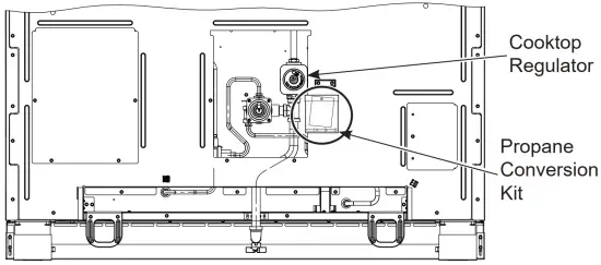
The propane orifices for the cooktop burners are shipped on the back of the range in the location shown.
TOOLS REQUIRED
- Adjustable wrench
- Socket wrench with 112· socket and extension
- Phillips head screwdriver
- Flat bladed screwdriver (blade approximately 3/32″ across)
- Nut drivers: 1/4″, 9/32″ or7mm
- 7mm open end wrench
- Phillips screwdriver
- Large flat blade screw driver
To adjust your range for use with propane gas, follow these instructions:
- Disconnect all electrical power, at the main circuit breaker or fuse box.
- Shut off the gas supply to the range by closing the manual shut-off valve.
CONVERTING THE PRESSURE REGULATOR
NOTE: Location varies by model.
If gas is detected at the regulator use a liquid leak detector to verify location.
NOTE: 48″ All Gas ranges have two regulators. All other ranges only have one regulator.
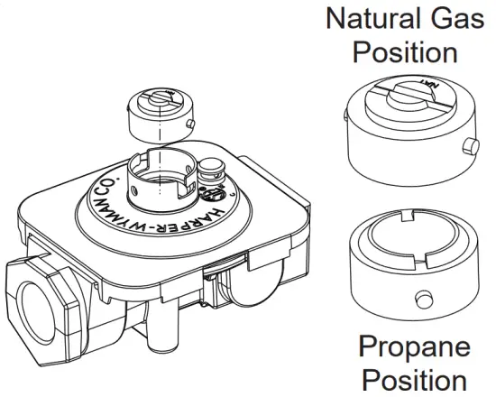
Cooktop Regulator
- Use a large flat blade screw driver to remove the cap from the pressure regulator.
- Turn the brass cap over for propane gas and reinstall into the regulator.

CONVERTING THE COOKTOP BURNERS
A. Remove the top grates, burner caps and burner heads.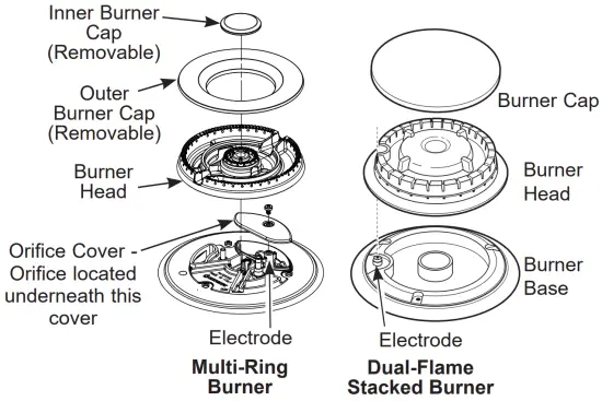
B. Using a 7 mm or 9/32″ nut driver for the Dual Stack buner, or a 7mm or 9/32″ open end wrench (only for Multi-ring) to remove the top burner orifices. These may be accessed through the burner opening in the base. The Multi-Ring orifice is accessed by removing the orifice cover using a Phillips screwdriver.
| NOTICE: Save these orifices for future conversion back to natural gas. |
C. Remove the propane orifices from the bag provided.
ZGU366
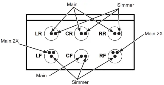
BURNER OUTPUT RATINGS: BTU/HR | |||
Propane Gas 10” W.C.P. | |||
BURNER | BTU RATE | ORIFICE SIZE | MARKING |
LF, RF | 21,000 | ||
Simmer | 0.52 mm | 52SL | |
Main 2X | 0.88 mm | 88XL | |
CF, CR | 10,000 | ||
Simmer | 0.34 mm | 34SL | |
Main | 0.88 mm | 88XL | |
LR, RR | 15,000 | ||
Simmer | 0.34 mm | 34SL | |
Main | 1.08 mm | 108XL | |
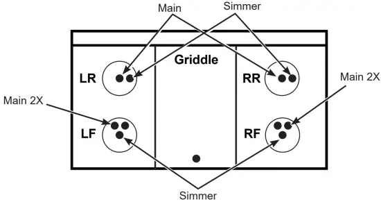
ZGU364
BURNER OUTPUT RATINGS: BTU/HR | |||
Propane Gas 10” W.C.P. | |||
BURNER | BTU RATE | ORIFICE SIZE | MARKING |
LF | 21,000 | ||
Simmer | 0.52 mm | 52SL | |
Main 2X | 0.88 mm | 88XL | |
RF | 21,000 | ||
Simmer | 0.52 mm | 52SL | |
Main 2X | 0.88 mm | 88XL | |
LR, RR | 15,000 | ||
| Simmer | 0.34 mm | 34SL | |
| Main | 1.08 mm | 108XL | |
| Griddle | 16,000 | 0.047″ | 047 |
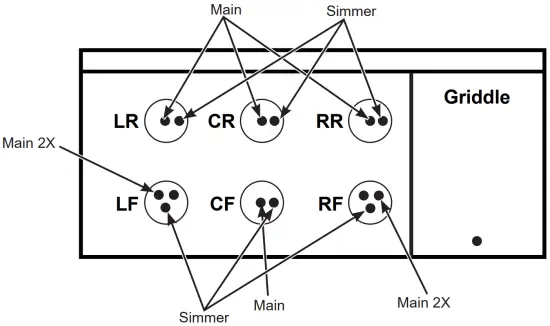
ZGU486
| BURNER OUTPUT RATINGS: BTU/HR | |||
| Propane Gas 10” W.C.P. | |||
| BURNER | BTU RATE | ORIFICE SIZE | MARKING |
| LF, RF | 21,000 | ||
| Simmer | 0.52 mm | 52SL | |
| Main 2X | 0.88 mm | 88XL | |
| CF, CR | 10,000 | ||
| Simmer | 0.34 mm | 34SL | |
| Main | 0.88 mm | 88XL | |
| LR, RR | 15,000 | ||
| Simmer | 0.34 mm | 34SL | |
| Main | 1.08 mm | 108L | |
| Griddle | 16,000 | 0.047″ | 047 |
D. Install the propane orifices in their precise locations. To prevent leakage, make sure the orifice spuds are securely hand tightened into the gas supply tubes. Orifice cover must be reinstalled.
E. Install the old orifice spuds into the bag along with these instructions, and replace onto the back of the range for possible future conversion.
CONVERT GRIDDLE ORIFICE
Locate the 3/4″ long griddle orifice. Select the proper orifice size for your gas and burner from the conversion chart.
A. Lift off the griddle flue cover. Remove the 2 inside clamping screws.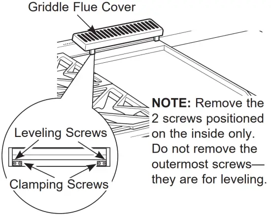
B. Lift out the cast-iron grease trough. Remove by sliding the griddle toward the rear and out of the hold-down tabs along the bottom.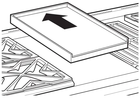
C. Remove the 4 screws on the capillary bracket and set bracket and capillary aside.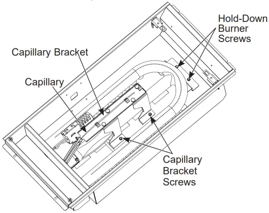
D. Remove the 2 hold-down screws at the rear of the burner. Pull the burner straight back toward the rear and out of the gas inlet.
E. Use a 1 /2″ deep well socket to remove and replace the orifice.
Reverse these steps to reassemble the griddle. Push excess capillary back into the entry hole. Place the unused orifice in the holder for possible future use.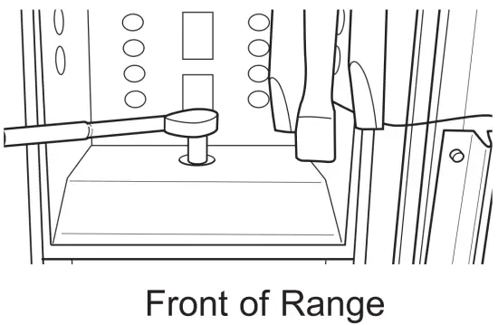
CHECK SURFACE BURNERS
Push and turn a knob to the LITE position. A clicking sound indicates proper operation of the ignition system. When lighting any burner, sparks will appear at all burners but gas flows from only the one selected. Once air is purged from the supply line, burner should light within 4 seconds. After burner lights, rotate the knob out of the LITE position. Try each burner in succession until all burners have been checked.
Quality of Flames
Determine the quality of flames visually. Normal burner flames should look like (A) or (8).
(A) Soft blue flames Normal for natural gas
B) Yellow tips on outer cones- Normal for propane gas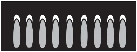
Long, bright yellow flames are not normal.
Normal flames may show signs of an orange tint when well heated or signs of flickering orange due to particles in the gas or air.
ADJUSTING LOW FLAME SETTING ON COOKTOP BURNERS
Low setting adjustments must be made with other burners in operation on a medium setting. This procedure prevents the low flame from being set too low, resulting in the flame being extinguished when other burners are turned on.
A. Turn on all surface burners to medium setting.
B. Multi-Ring Burners – Outer Ring and Inner Ring
- Rotate the knob to the MED setting.
- Remove the knob and insert a small flat blade screwdriver into the valve shaft and turn clockwise to tighten down the bypass set screw. Hold outer shaft while turning inner screw.

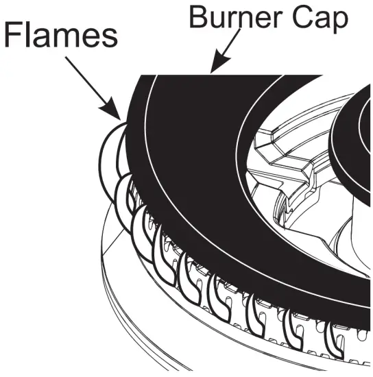
- The OUTER RING flames should be adjusted so that they barely curl over the top edge of the burner cap as shown
- If the flame appears too low or unstable, slowly turn bypass screw counterclockwise until a stable flame exists for each burner. Remember, other burner must be turned on to MED.

- To further test the OUTER RING flame, set the burner to MED for at least 4 seconds, then turn to HI. If Bur er Cap the flames turn yellow, slowly increase the OUTER RING flame by turning the OUTER RING by-pass screw slightly counterclockwise and check again.
- Replace knob and rotate knob to the LO setting.
- Remove the knob AND the right side bezel screw as shown.
- The INNER RING flames should be adjusted by inserting a small flat blade screwdriver into the bezel screw hole and turning clockwise to tighten down the bypass set screw with the knob at the LO setting. Locate the screw through the hole with a flashlight if necessary.
- If the flame appears too low or unstable, slowly turn bypass screw counterclockwise until a stable flame exists for each burner. Remember, other burner must be turned on to MED. When adjusting, make sure the low flame is contacting the ignitor and the burner head is grounded properly or the spark module will continue to attempt to reignite the flame.
- Reinstall right side bezel screw. Do not over tighten. Replace the knob.
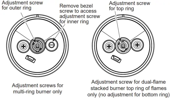
C. Dual-Flame Stacked Burners – Upper Flames
- Rotate the knob to the MED setting.
- Remove the knob.
- The upper ring of flames should be adjusted with the knob at the MED setting by adjusting the set screw in the center valve shaft. Hold outer shaft while turning inner screw. The flames should be adjusted so that they barely curl over the top edge of the burner cap.
- Replace knob
D. Additionally quickly open the over door while observing flame. If flame is extinguished, continue adjusting set screw for a larger flame. Repeat door openings until flame is stable.
SPECIAL NOTE:
To convert the oven back to natural gas, reverse the instructions given in making propane adjustments. Save these orifices for future conversion back to natural gas.
ADDITIONAL INFORMATION
ZGU366
| BURNER OUTPUT RATINGS: BTU/HR | |||
| NG (Natural) Gas 5” W.C.P. | |||
BURNER | BTU RATE | ORIFICE SIZE | MARKING |
| LF, RF | 23,000 | ||
| Simmer | 0.82 mm | 82SN | |
| Main 2X | 1.46 mm | 146XN | |
| CF, CR | 15,000 | ||
| Simmer | 0.51 mm | 51SN | |
| Main | 1.68 mm | 168N | |
| LR, RR | 18,000 | ||
| Simmer | 0.51 mm | 51SN | |
| Main | 1.86 mm | 186N | |
| Broil | 18,000 | 0.074″ | 74N |
| Bake | 23,500 | 0.085” | 85N |
ZGU364
| BURNER OUTPUT RATINGS: BTU/HR | |||
| NG (Natural) Gas 5” W.C.P. | |||
BURNER | BTU RATE | ORIFICE SIZE | MARKING |
| LF | 23,000 | ||
| Simmer | 0.82 mm | 82SN | |
| Main 2X | 1.46 mm | 146XN | |
| RF | 21,000 | ||
| Simmer | 0.82 mm | 82SN | |
| Main 2X | 1.52 mm | 152XN | |
| LR, RR | 15,000 | ||
| Simmer | 0.51 mm | 51SN | |
| Main | 1.68 mm | 168N | |
| Griddle | 18,000 | 0.076” | 076 |
| Broil | 18,000 | 0.074″ | 74N |
| Bake | 23,500 | 0.085” | 85N |
ZGU486
| BURNER OUTPUT RATINGS: BTU/HR | |||
| NG (Natural) Gas 5” W.C.P. | |||
| BURNER | BTU RATE | ORIFICE SIZE | MARKING |
| LF, RF | 23,000 | ||
| Simmer | 0.82 mm | 82SN | |
| Main 2X | 1.46 mm | 146XN | |
| CF, CR | 15,000 | ||
| Simmer | 0.51 mm | 51SN | |
| Main | 1.68 mm | 168N | |
| LR, RR | 18,000 | ||
| Simmer | 0.51 mm | 51SN | |
| Main | 1.86 mm | 186N | |
| Griddle | 18,000 | 0.076” | 076 |
PROPANE CONVERSION INSTRUCTIONS
31-2000799 Rev. 3 02-22 GEA
ZGU366, ZGU364, ZGU486


