![]()

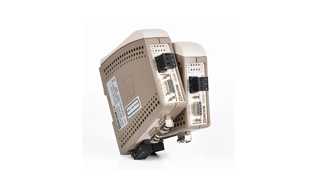
ODW-730-F1
Fibre Optic Modem
Industrial Converter RS-485 to Fibre Optic Link
Point to Point applications
General information
Legal information
The contents of this document are provided “as is”. Except as required by applicable law, no warranties of any kind are made in relation to the accuracy and reliability or contents of this document, either expressed or implied, including but not limited to the implied warranties of merchantability and fitness for a particular purpose. Westermo reserves the right to revise this document or withdraw it at any time without prior notice.
Under no circumstances shall Westermo be responsible for any loss of data or income or any special, incidental, and consequential or indirect damages howsoever caused.
More information about Westermo can be found at www.westermo.com
Safety and Regulations
Warning signs are provided to prevent personal injury and/or damages to the product.
The following levels are used:
| Level of warning | Description | Consequence personal injury | Consequence material damage |
 WARNING | Indicates a potentially hazardous situation | Possible death or major injury | Major damage to the product |
 CAUTION | Indicates a potentially hazardous situation | Minor or moderate injury | Moderate damage to the product |
 NOTICE | Provides information in order to avoid misuse of the product, confusion or misunderstanding | No personal injury | Minor damage to the product |
| Used for highlighting general, but important information | No personal injury | Minor damage to the product |

Before installation:
Read this manual completely and gather all information on the product. Make sure that you understand it fully. Check that your application does not exceed the safe operating specifications for this product.
WARNING – SAFETY DURING INSTALLATION
The product must be installed by qualified service personnel and built in to an apparatus cabinet or similar, where access is restricted to service personnel only.
WARNING – HAZARDOUS VOLTAGE
Do not open an energized product. Hazardous voltage may occur when connected to a power supply.
WARNING – PROTECTIVE FUSE
It must be possible to disconnect manually from the power supply. Ensure compliance to national installation regulations. Replacing the internal fuse must only be performed by Westermo qualified personell.
CAUTION – CLASS 1 LASER PRODUCT
Do not look directly into a fibre optical port or any connected fibre, although the product is designed to meet the Class 1 Laser regulations and complies with 21 CFR 1040.10 and 1040.11.
CAUTION – ELECTROSTATIC DISCHARGE (ESD)
Prevent electrostatic discharge damages to internal electronic parts by discharging your body to a grounding point (e.g. use a wrist strap).
CAUTION – HANDLING OF SFP TRANSCEIVERS
SFP transceivers are supplied with plugs to avoid contamination inside the optical port. They are very sensitive to dust and dirt. If the fibre is disconnected from the product, the protective plugs on the transmitter/receiver must be connected. The protective plugs must be kept on during transportation. The fibre optics cables must be handled the same way.
Care recommendations
Follow the care recommendations below to maintain full operation of product and to fulfill the warranty obligations:
- Do not drop, knock or shake the product. Rough handling above the specification may cause damage to internal circuit boards.
- Use a dry or slightly water-damp cloth to clean the product. Do not use harsh chemicals, cleaning solvents or strong detergents.
- Do not paint the product. Paint can clog the product and prevent proper operation.
If the product is used in a manner not according to specification, the protection provided by the equipment may be impaired.
If the product is not working properly, contact the place of purchase, nearest Westermo distributor office or Westermo technical support.
Cleaning of the optical connectors
In the event of contamination, the optical connectors should only be cleaned by the use of recommended cleaning fluids and correct cleaning equipment.
Recommended cleaning fluids:
- Methyl-, ethyl-, isopropyl- or isobutyl-alcohol
- Hexane
- Naphtha
Product disposal

This symbol means that the product shall not be treated as unsorted municipal waste when disposing of it. It needs to be handed over to an applicable collection point for recycling electrical and electronic equipment.
By ensuring this product is disposed of correctly, you will help to reduce hazardous substances and prevent potential negative consequences to both environment and human health, which could be caused by inappropriate disposal.
Declaration of Conformity
Hereby, Westermo declares that this product is in compliance with applicable EU directives and UK legislations. The full declaration of conformity and other detailed information is available at www.westermo.com/support/product-support.


Agency approvals and standards compliance
| Type | Approval / Compliance |
| EMC | EN 61000-6-1, Immunity residential environments |
| EN 61000-6-2, Immunity industrial environments | |
| EN 61000-6-3, Emission residential environments | |
| EN 61000-6-4, Emission industrial environments | |
| EN 50121-4, Railway signalling and telecommunications apparatus | |
| IEC 62236-4, Railway signalling and telecommunications apparatus | |
| DNV Standard for Certification no. 2.4 | |
| Safety | UL/CSA 60950-1, IT equipment |
FCC Part 15.105 Notice:
This equipment has been tested and found to comply with the limits for a Class A digital device, pursuant to Part 15 of the FCC Rules. These limits are designed to provide reasonable protection against harmful interference when the equipment is operated in a commercial environment.
This equipment generates, uses, and can radiate radio frequency energy and, if not installed and used in accordance with the instruction manual, may cause harmful interference to radio communications. Operation of this equipment in a residential area is likely to cause harmful interference in which case the user will be required to correct the interference at his own expense.
Type tests and environmental conditions
| Electromagnetic Compatibility | |||
| Phenomena | Test | Description | Level |
| ESD | EN 61000-4-2 | Enclosure contact | ± 6 kV |
| Enclosure air | ± 8 kV | ||
| RF field AM modulated | IEC 61000-4-3 | Enclosure | 10 V/m 80% AM (1 kHz), 80 - 800 MHz 20 V/m 80% AM (1 kHz), 800 - 1000 MHz 20 V/m 80% AM (1 kHz), 1400 – 2700 MHz |
| RF field 900 MHz | ENV 50204 | Enclosure | 20 V/m pulse modulated 200 Hz, 900 ± 5 MHz |
| Fast transient | EN 61000-4-4 | Signal ports | ± 2 kV |
| Power ports | ± 2 kV | ||
| Surge | EN 61000-4-5 | Signal ports unbalanced | ± 2 kV line to earth, ± 2 kV line to line |
| Signal ports balanced | ± 2 kV line to earth, ± 1 kV line to line | ||
| Power ports | ± 2 kV line to earth, ± 2 kV line to line | ||
| RF conducted | EN 61000-4-6 | Signal ports | 10 V 80% AM (1 kHz), 0.15 - 80 MHz |
| Power ports | 10 V 80% AM (1 kHz), 0.15 - 80 MHz | ||
| Pulse Magnetic field | EN 61000-4-9 | Enclosure | 300 A/m, 6.4 / 16 µs pulse |
| Mains freq. 50 Hz | EN 61000-4-16 | Signal ports | 100 V 50 Hz line to earth |
| Mains freq. 50 Hz | SS 436 15 03 | Signal ports | 250 V 50 Hz line to line |
| Radiated emission | CISPR 16-2-3 | Enclosure | EN 61000-6-3 |
| ANSI C63.4 | FCC part 15 | ||
| Conducted emission | CISPR 16-2-1 | AC power ports | EN 61000-6-3 |
| ANSI C63.4 | AC power ports | FCC part 15 | |
| CISPR 16-2-1 | DC power ports | EN 61000-6-4 | |
| Dielectric strength | UL 60950 | Signal port to all other isolated ports | 2 kVrms 50 Hz 1min |
| Power port to other isolated ports | 3 kVrms 50 Hz 1min 2 kVrms 50 Hz 1min (@ rated power < 60V) | ||
| Environmental | |||
| Temperature | EN 60068-2-1 EN 60068-2-2 | Operating | - 40 to +70°C |
| Storage & Transport | - 40 to +70°C | ||
| Maximum surface temperature | 135ºC (temperature class T4) | ||
| Humidity | EN 60068-2-30 | Operating | 5 to 95% relative humidity |
| Storage & Transport | 5 to 95% relative humidity | ||
| Altitude | Operating | 2 000 m / 70 kPa | |
| Service life | Operating | 10 year | |
| Vibration | IEC 60068-2-6 | Operating | 7.5 mm, 5 - 8 Hz 2 g, 8 - 500 Hz |
| Shock | IEC 60068-2-27 | Operating | 15 g, 11 ms |
| Packaging | |||
| Enclosure | UL 94 | PC / ABS | Flammability class V-1 |
| Dimension W x H x D | 35 x 121 x 119 mm | ||
| Weight | 0.26 kg | ||
| Degree of protection | IP21 | ||
| Cooling | IEC 529 | Enclosure | Convection |
| Mounting | Horizontal on 35 mm DIN-rail | ||
Functional description
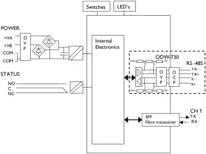
OVP Over Voltage Protection
OCP Over Current Protection
Converter serial interface - optical fibre
ODW-730 is a fibre optic modem that converts between electrical RS-485 and a fibre optical link.
ODW-730 can also be used to convert from RS-485 to RS-232 by using a ODW-730 in the same link as ODW-720.
Repeater - optical fibre links
ODW-730 is a fibre optic repeater that repeats received data from one fibre link out to the other link. This is useful e.g. for long distance communication, where electromagnetic interference may occur or when isolation of the electrical network is needed. The maximum optical fibre distance depends on selected fibre transceiver and fibre type. Distances up to 80 km (50 miles) are available.
Interface specifications
| Power | |
| Rated voltage | 12 to 48 VDC and 24 VAC |
| Operating voltage | 10 to 60 VDC and 20 to 30 VAC |
| Rated current | 300 mA @ 12 V 150 mA @ 24 V 75 mA @ 48 V |
| Rated frequency | DC and 48 to 62 Hz |
| Inrush current I²t | 0.2 A²s |
| Startup current* | 1.0 Apeak |
| Polarity | Reverse polarity protected |
| Redundant power input | Yes |
| Isolation to | RS-485 and Status port |
| Connection | Detachable screw terminal |
| Connector size | 0.75 - 2.5 mm2 (AWG 18 - 13) Connect the unit using at least 18 AWG (0.75 mm2) wiring |
| Shielded cable | Not required |
* External supply current capability for proper startup
| Status | |
| Port type | Signal relay, changeover contacts |
| Rated voltage | Up to 48 VDC |
| Operating voltage | Up to 60 VDC |
| Contact rating | 500 mA @ 48 VDC |
| Contact resistance | < 50 mΩ |
| Isolation to | RS-485 and Power port |
| Connection | Detachable screw terminal |
| Connector size | 0.2 - 2.5 mm² (AWG 24 - 13) |
| Shielded cable | Not required |
Branch circuit protection (fuse) is required for this unit with rating not exceeding 20 A. Product should be connected to UL Listed power supplies rated 12 - 48 VDC, min 500 mA or 24 VAC, min 500 mA or reliably grounded DC SELV source.
| RS-422/485 | |
| Electrical specification | EIA RS-485, 2-wire or 4-wire twisted pair |
| Data rate | 300 bit/s - 1.5 Mbit/s |
| Data format | 9 - 12 bits |
| Protocol | Start-bit followed by 8-11 bits |
| Retiming | Yes |
| Turning time (2-wire RS-485) | One tbit tbit = 1 / Baud rate (Baud rate in bit/s) |
| Transmission range | < 1200 m, depending on data rate and cable type (EIA RS-485) |
| Settings | 120 Ω termination and failsafe biasing 680 Ω |
| Protection | Installation Fault Tolerant (up to ±60 V) |
| Isolation to | Status and Power port |
| Connection | Detachable screw terminal |
| Connector size | 0.2 - 2.5 mm² (AWG 24 – 13) |
| Shielded cable | Not required |
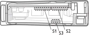
Location of Interface ports, LED’s and DIP-switches
ODW-730-F1
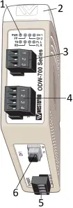
- LED Indicators
- DIP-switches accessible under lid
- Status screw terminal
- RS-422/485 screw terminal
- Power screw terminal
- FX(Fibre)
3 Status screw terminal
| Position | Description | Product marking |
| 1 | Contact with C when fibre optical links are in operation | NO |
| 2 | Common | C |
| 3 | Open (no contact with C) when fibre optical links are in operation | NC |
4 RS-422/485 screw terminal
| Position | Direction* | Description | Product marking |
| 1 | In | R+ (EIA RS-485 A’) | R+ |
| 2 | In | R- (EIA RS-485 B’) | R- |
| 3 | In/Out | T+ (EIA RS-485 A) | T/R+ |
| 4 | In/Out | T- (EIA RS-485 B) | T/R- |
5 Power screw terminal
| Position | Direction* | Description | Product marking |
| 1 | In | Common voltage | COM |
| 2 | In | Voltage A | +VA |
| 3 | In | Voltage B | +VB |
| 4 | In | Common voltage | COM |
* Direction relative this unit
LED indicators
| LED | Status | Description |
| PWR Power | ON | Power is on. |
| OFF | Power is off. | |
| FP | Not used | |
| CH 2 | Not used | |
| CH 1 Channel 1 link status | ON | Fiber link to other unit has been established at CH 1. |
| Flashing | Optical power detected but link to other unit has not been established at CH 1. | |
| OFF | No optical power detected and no link to other unit has been established at CH 1. | |
| TD | Flash | Data received on the electrical interface and transmitted out on the optical interface. |
| OFF | No data received on the electrical interface. | |
| RD | Flash | Data received on the optical interface and transmitted out on the electrical interface. |
| OFF | No data received on the optical interface. | |
| FL R Failure link remote | ON | Remote fibre link failure. A fibre link is out of operation at any other unit than this one*. |
| Flashing | Hardware error or invalid configuration. | |
| FL L Failure link local | ON | Local fibre link failure. A fibre link is out of operation at this unit. |
| Flashing | Hardware error or invalid configuration. |
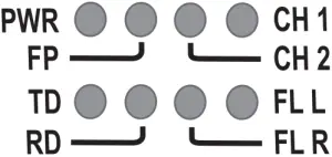
* Only valid if used togheter with ODW-720-F1 units in a multidrop network.
Note: During power up, all LED’s will turn on for about 1 second.
DIP-switch settings
CAUTION – ELECTROSTATIC DISCHARGE (ESD)
Prevent electrostatic discharge damages to internal electronic parts by discharging your body to a grounding point (e.g. use a wrist strap).
S1 DIP-switch, asynchronous mode speed selection
 300 bit/s
 57.6 kbit/s
 1.0 Mbit/s
 1200 bit/s
  115.2 kbit/s
  1.5 Mbit/s
 2400 bit/s
  125 kbit/s
  9 bits data format
 4800 bit/s
  187.5 kbit/s
  10 bits data format
 9600 bit/s
  230.4 kbit/s
  11 bits data format
 19.2 kbit/s
  250 kbit/s
 12 bits data format
 38.4 kbit/s
  500 kbit/s
  S:1:8 always OFF for point-to-point applications
| Supervision table when selecting data format | ||||||||
| Start bit | ||||||||
| 7 bit | ||||||||
| 8 bit | ||||||||
| Parity | ||||||||
| 1 stop bit | ||||||||
| 2 stop bit | ||||||||
| Number of bit | 9 | 10 | 10 | 10 | 11 | 11 | 11 | 12 |
S1 DIP-switch, synchronous mode time frame selection
 1.6 ms
  13 µs
13 µs 2 µs
2 µs
 416 µs
  8.6 µs
 1 µs
1 µs
 208 µs
 4.3 µs
 500 ns
 104 µs
 4 µs
4 µs 300 ns
 52 µs
52 µs 2.6 µs
 S:1:8 always OFF for point-to-point applications
 26 µs
26 µs 2.1 µs
S2 DIP-switch
 RS-485, 2-wire
  S2:2 and S2:4 - S2:8 always OFF, S2:3 always ON for point-to-point applications
 RS-422, 4-wire
S3 DIP-switch
 No termination and fail-safe
  Termination with fail-safe (2-wire)
 Termination with fail-safe (4-wire)
Factory default
 S1
S1  S2
S2
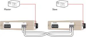
Start up guide, point-to-point application
Follow the steps below to get the unit up and running in a simple application.
![]() Make sure that DIP-switches S1:8 and S2:2 - S2:8 are set to factory default positions. (I.e. S1:8 OFF, S2:2 OFF, S2:3 ON and S”:4 - S2:8 OFF).
Make sure that DIP-switches S1:8 and S2:2 - S2:8 are set to factory default positions. (I.e. S1:8 OFF, S2:2 OFF, S2:3 ON and S”:4 - S2:8 OFF).![]() Configure both ODW-730-F1 units for the correct speed and data format using DIP-switches S1:1 - S1:7.
Configure both ODW-730-F1 units for the correct speed and data format using DIP-switches S1:1 - S1:7.![]() Select RS-485 2- or 4-wire mode using DIP-switch S2:1 (OFF = 2-wire, ON = 4-wire).
Select RS-485 2- or 4-wire mode using DIP-switch S2:1 (OFF = 2-wire, ON = 4-wire).![]() Enable the RS-485 termination / fail safe if required using DIP-switches S3:1 - S3:4
Enable the RS-485 termination / fail safe if required using DIP-switches S3:1 - S3:4
(S3:1 asnd S3:2 = 4-wire termination, S3:3 and S3:4 = 2-wire connection.)![]() Connect the fibre link between the ODW-730-F1.
Connect the fibre link between the ODW-730-F1.![]() Connect the power supply to both ODW-730-F1.
Connect the power supply to both ODW-730-F1.![]() After a few seconds the fibre link should be in operation, indicated by an active CH1 LED.
After a few seconds the fibre link should be in operation, indicated by an active CH1 LED.![]() Connect the serial cables from PLC master and slave to respective ODW-730-F1.
Connect the serial cables from PLC master and slave to respective ODW-730-F1.![]() Frames from PLC master that are correctly received in the ODW-730-F1 will be indicated by flashing TD LED.
Frames from PLC master that are correctly received in the ODW-730-F1 will be indicated by flashing TD LED.![]() Frames that are received via the fibre link will be transmitted to the PLC slave and indicated by flashing RD LED.
Frames that are received via the fibre link will be transmitted to the PLC slave and indicated by flashing RD LED.![]() Replies from slave to master will be transferred and indicated in the opposite way.
Replies from slave to master will be transferred and indicated in the opposite way.![]() The point-to-point application is up and running.
The point-to-point application is up and running.
RS-485 termination at system level
The system should be installed in according to the RS-485 specification. A system should always form a bus structure where the termination is at the end points of the bus. See diagrams for details of how this is done with RS-485 2-wire and 4-wire.
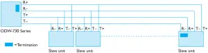
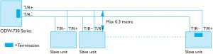
N.B. R+/R-, T+/T- definitions are not standard, it can help to shift + and - if the unit does not work.
About the interfaces
Power terminal
The power terminal has two independent inputs, +VA and +VB, allowing redundancy should either fail. The ODW-730 power supply is galvanically isolated from all other internal electronics.
Optical fibre interfaces
ODW-730 uses Small From Factor Pluggable (SFP) transceivers that are in compliance with the Multi-Sourcing Agreement (MSA). This means that a wide range of different fibre tranceivers and connectors can be used. For supported transceivers, see SFP data sheet.
RS-485 interface
A 4 position detachable screw terminal that can handle full duplex data rates up to 1.5 Mbit/s and can be set to either 2- or 4-wire RS-485 system.
When 4-wire RS-485 is selected, the terminals T/R+ and T/R- will always be set to transmit and terminals R+ and R- will always receive data.
Manchester coded protocol can be transferred with Synchronuous mode.
Status port
The status port connects to an internal relay wich may be used to trigger an external alarm if a fault condition occurs. During normal operation pins 1 and 2 are in contact with each other, and pins 2 and 3 are isolated. During an optical link failure, or power failure, pins 1 and 2 are isolated, and pins 2 and 3 are in contact with each other.
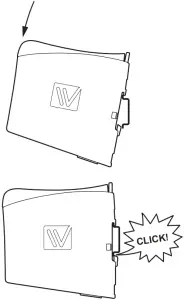
Mounting
This unit should be mounted on 35 mm DIN-rail, which is horizontally mounted inside an apparatus cabinet, or similar.
Snap on mounting, see figure.
Cooling
This unit uses convection cooling. To avoid obstructing the airflow around the unit, use the following spacing rules.
Minimum spacing 25 mm (1.0 inch) above /below and 10 mm (0.4 inches) left /right the unit. Spacing is recommended for the use of unit in full operating temperature range and service life.
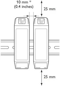
* Spacing (left/right) recommended for full operating temperature range
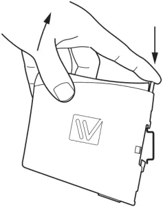
Removal
Press down the black support at the top of the unit. See figure.
![]()
Westermo • Metallverksgatan 6, SE-721 30 Västerås, Sweden
Tel +46 16 42 80 00 Fax +46 16 42 80 01
E-mail: [email protected]
www.westermo.com
REV. M 6651-2241 2021-04 Westermo Network Technologies AB, Sweden


