![]()

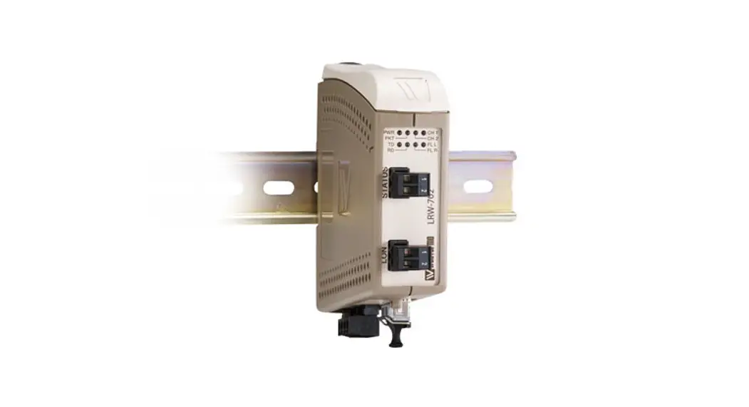
LRW-702-F2
Fibre Optic industrial converter/repeater for LonWorks® TP/FT-10 point-to-point, line, and redundant ring
General information
Legal information
The contents of this document are provided “as is”. Except as required by applicable law, no warranties of any kind, either express or implied, including, but not limited to, the implied warranties of merchantability and fitness for a particular purpose, are made in relation to the accuracy and reliability or contents of this document. Westermo reserves the right to revise this document or withdraw it at any time without prior notice.
Under no circumstances shall Westermo be responsible for any loss of data or income or any special, incidental, consequential, or indirect damages howsoever caused.
More information about Westermo can be found at www.westermo.com.
Safety and Regulations
Warning signs are provided to prevent personal injury and/or damage to the product.
The following levels are used:
| Level of warning | Description | Consequence personal injury | Consequence material damage |
| Indicates a potentially hazardous situation | Possible death or major injury | Major damage to the product |
| Indicates a potentially hazardous situation | Minor or moderate injury | Moderate damage to the product |
| Provides information in order to avoid misuse of the product, confusion, or misunderstanding | No personal injury | Minor damage to the product |
| Used for highlighting general, but important information | No personal injury | Minor damage to the product |
 WARNING
 CAUTION
 NOTICE
 NOTE
NOTEBefore Installation
Read this manual completely and gather all information on the product. Make sure that you understand it fully. Check that your application does not exceed the safe operating specifications for this product.
![]() SAFETY DURING INSTALLATION
SAFETY DURING INSTALLATION
The product must be installed by qualified service personnel and built into an apparatus cabinet or similar, where access is restricted to service personnel only.
Refer to Compliance Information to see the required level of qualified service personnel according to safety standards.
During installation, ensure a protective earthing conductor is first connected to the protective earthing terminal (only valid for metallic housings). Westermo recommends a cross-sectional area of at least 4 mm2.
Upon removal of the product, ensure that the protective earthing conductor is disconnected last.
![]() HAZARDOUS VOLTAGE
HAZARDOUS VOLTAGE
Do not open an energized product. Hazardous voltage may occur when connected to a power supply.
![]() PROTECTIVE FUSE
PROTECTIVE FUSE
The power supply wiring must be sufficiently fused. The fuse must be IEC 60127 certified and rated for T1.25 A and 250 V.
It must be possible to disconnect manually from the power supply.
Ensure compliance with national installation regulations.
This product has no internal fuse and should be connected via an external fuse for protection.
![]() CLASS 1 LASER PRODUCT
CLASS 1 LASER PRODUCT
Do not look directly into a fibre optical port or any connected fibre, although the product is designed to meet the Class 1 Laser regulations and complies with 21 CFR 1040.10 and 1040.11.
![]() FIBRE OPTIC HANDLING
FIBRE OPTIC HANDLING
Fibre optic equipment needs special treatment. It is very sensitive to dust and dirt. If the fibre is disconnected from the product, the protective plugs on the transmitter/receiver must be connected. The protective plugs must be kept on during transportation. The fibre optics cables must be handled the same way.
![]() ELECTROSTATIC DISCHARGE (ESD)
ELECTROSTATIC DISCHARGE (ESD)
Prevent electrostatic discharge damage to internal electronic parts by discharging your body to a grounding point (e.g. use a wrist strap).
Care Recommendations
Follow the care recommendations below to maintain the full operation of the product and to fulfil the warranty obligations:
- Do not drop, knock or shake the product. Rough handling above the specification may cause damage to internal circuit boards.
- Use a dry or slightly water-damp cloth to clean the product. Do not use harsh chemicals, cleaning solvents or strong detergents.
- Do not paint the product. Paint can clog the product and prevent proper operation.
If the product is used in a manner not according to specification, the protection provided by the equipment may be impaired.
If the product is not working properly, contact the place of purchase, nearest Westermo distributor office or Westermo technical support.
Cleaning of the Optical Connectors
In the event of contamination, the optical connectors should be cleaned by the use of forced nitrogen and some kind of cleaning stick.
Recommended cleaning fluids:
- Methyl-, ethyl-, isopropyl- or isobutyl-alcohol
- Hexane
- Naphtha
Product Disposal
![]() This symbol means that the product shall not be treated as unsorted municipal waste when disposed of it. It needs to be handed over to an applicable collection point for recycling electrical and electronic equipment.
This symbol means that the product shall not be treated as unsorted municipal waste when disposed of it. It needs to be handed over to an applicable collection point for recycling electrical and electronic equipment.
By ensuring this product is disposed of correctly, you will help to reduce hazardous substances and prevent potential negative consequences to both environment and human health, which could be caused by inappropriate disposal.
Declaration of Conformity
Hereby, Westermo declares that this product is in compliance with applicable EU directives and UK legislation. The full declaration of conformity and other detailed information is available at www.westermo.com/support/product-support.
![]()
![]()
Agency Approvals and Standards Compliance
| Type | Approval/Compliance |
| EMC | EN 61000-6-2, Immunity industrial environments |
| EN 61000-6-4, Emission industrial environments |
FCC Part 15.105 Notice:
This equipment has been tested and found to comply with the limits for a Class A digital device, pursuant to Part 15 of the FCC Rules. These limits are designed to provide reasonable protection against harmful interference when the equipment is operated in a commercial environment.
This equipment generates, uses, and can radiate radio frequency energy and, if not installed and used in accordance with the instruction manual, may cause harmful interference to radio communications. Operation of this equipment in a residential area is likely to cause harmful interference in which case the user will be required to correct the interference at his own expense.
Type Tests and Environmental Conditions
| Electromagnetic Compatibility | |||
| Phenomena | Test | Description | Level |
| ESD | EN 61000-4-2 | Enclosure contact | ± 4 kV |
| Enclosure air | ± 8 kV | ||
| RF field AM modulated | IEC 61000-4-3 | Enclosure | 10 V/m 80% AM (1 kHz) |
| Fast transient | EN 61000-4-4 | Signal ports | ± 1 kV |
| Power ports | ± 2 kV | ||
| Surge | Signal ports balanced | ± 1 kV line to earth, ± 1 kV line to line | |
| Power ports | ± 0.5 kV line to earth, ± 0.5 kV line to line | ||
| RF conducted | EN 61000-4-6 | Signal ports | 10 V 80% AM (1 kHz), 0.15 – 80 MHz |
| Power ports | 10 V 80% AM (1 kHz), 0.15 – 80 MHz | ||
| Power frequency magnetic field | EN 61000-4-8 | Enclosure | 100 A/m, 50 Hz, 16.7 Hz & 0 Hz |
| Pulse Magnetic field | EN 61000-4-9 | Enclosure | 300 A/m, 6.4 / 16 µs pulse |
| Voltage dips and interruption | EN 61000-4-11 | AC power ports | 10 & 5 000 ms, interruption 10 & 500 ms, 30% reduction 100 & 1 000 ms, 60% reduction |
| Mains freq. 50 Hz | EN 61000-4-16 | Signal ports | 100 V 50 Hz line to earth |
| Mains freq. 50 Hz | SS 436 15 03 | Signal ports | 250 V 50 Hz line to line |
| Voltage dips and interruption | EN 61000-4-29 | DC power ports | 10 & 100 ms, interruption 10 ms, 30% reduction 10 ms, 60% reduction +20% above & –20% below rated voltage |
| Radiated emission | CISPR 16-2-3 ANSI C63.4 (FCC part 15) | Enclosure | Class B |
| Class A | |||
| Conducted emission | CISPR 16-2-1 ANSI C63.4 (FCC part 15b) | AC power ports | Class B |
| AC power ports | Class B | ||
| DC power ports | Class A | ||
| Dielectric strength | EN 60950 | Signal port to all other isolated ports | 1.5 kVrms 50 Hz 1min |
| Power port to other isolated ports | 2 kVrms 50 Hz 1min | ||
| Environmental | |||
| Temperature | EN 60068-2-1 EN 60068-2-2 | Operating | –40 to +60ºC LRW-702-F2 |
| Storage & Transport | –40 to +70°C | ||
| Humidity | EN 60068-2-30 | Operating | 5 to 95% relative humidity |
| Storage & Transport | 5 to 95% relative humidity | ||
| Altitude | Operating | 2 000 m / 70 kPa | |
| Service life | Operating | 10 years | |
| Vibration | IEC 60068-2-6 | Operating | 7.5 mm, 5 – 8 Hz 2 g, 8 – 500 Hz |
| Shock | IEC 60068-2-27 | Operating | 15 g, 11 ms |
| Packaging | |||
| Enclosure | UL 94 | PC / ABS | Flammability class V-1 |
| Dimension W x H x D | 35 x 121 x 119 mm | ||
| Weight | 0.26 kg | ||
| Degree of protection | IEC 529 | Enclosure | IP 21 |
| Cooling | Convection | ||
| Mounting | Horizontal on 35 mm DIN-rail | ||
Functional Description
Converter TP/FT Interface – Optical Fibre
The LRW-702-F2 is a fiber optic converter that converts between LonWorks® TP/FT, and fiber optical link.
Repeater – Optical Fibre Links
The LRW-702-F2 is a fiber optic repeater that repeats received data from one fiber link out to the other link. This is useful e.g. for long-distance communication, where electromagnetic interference may occur or when isolation of the electrical network is needed.
Singlemode or Multimode LC Fibre Connectors
The LRW-702-F2 uses Small Form Factor Pluggable (SFP) transceivers that are in compliance with the Multi-Sourcing Agreement (MSA). A wide range of different fiber transceivers and connectors can be used.
Interface Specifications
| Power | |
| Rated voltage | 12 to 48 VDC 24 VAC |
| Operating voltage | 10 to 60 VDC 20 to 30 VAC |
| Rated current | 400 mA @ 12 VDC 200 mA @ 24 VDC 100 mA @ 48 VDC |
| Rated frequency | DC AC: 48 to 62 Hz |
| Inrush current I2t | 0.2 A2s |
| Startup current* | 1.0 Apeak |
| Polarity | Reverse polarity protected |
| Redundant power input | Yes |
| Isolation to | TP/FT-10 port and status port |
| Connection | 4-position detachable screw terminal |
| Connector size | 0.2 – 2.5 mm2 (AWG 24 – 12) |
| Shielded cable | Not required |
* External supply current capability for a proper startup.
| Status | |
| Port type | Solid-state relay |
| Operating voltage | Up to 60 VDC |
| Load current | Up to 100 mA |
| Contact resistance | 8 W |
| Isolation to | TP/FT-10 port and power port |
| Connection | 2-position detachable screw terminal |
| Connector size | 0.2 – 2.5 mm2 (AWG 24 – 12) |
| TP/FT-10 | |
| Electrical specification | LONWORKS® TP/FT-10 using FTT-10A transceiver |
| Data rate | 78.5 kbit/s |
| Data format | Synchronous |
| Protocol | LonTalk® |
| Transmission range | Up to 2700 m |
| Termination | Single or double external termination according to TP/FT-10 specification |
| Isolation to | The power port and status port |
| Connection | 2-positon detachable screw terminal |
| Connector size | 0.2 – 2.5 mm2 (AWG 24 – 12) |
| Shielded cable | Not required |
| Conductive housing | No |
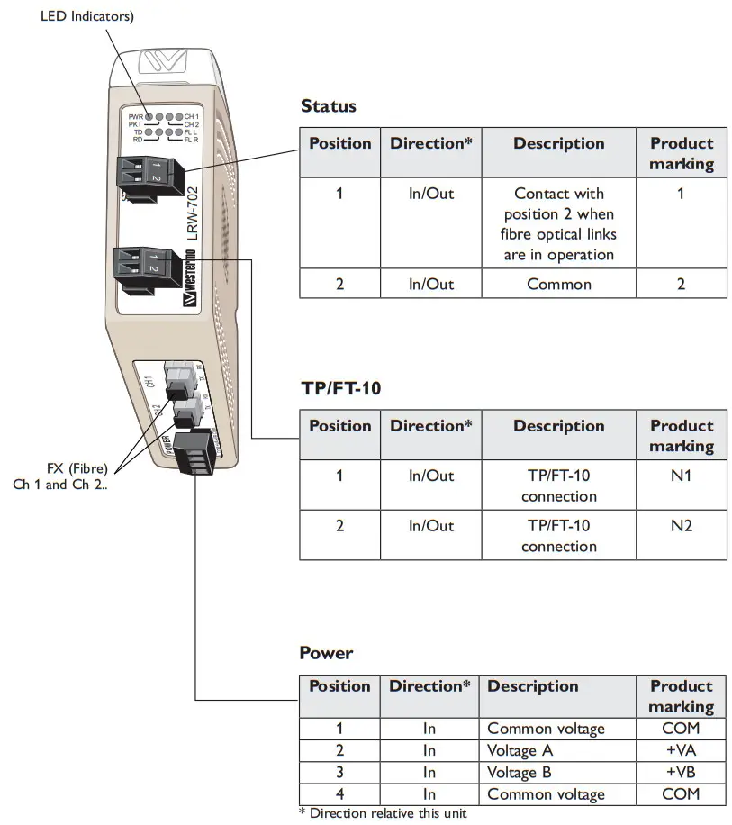
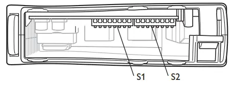
Location of Interface Ports, LEDs, and DIP-switches
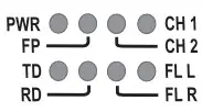
LED Indicators
| LED | Status | Description |
| PWR Power | ON | The power is on. |
| OFF | The power is off. | |
| FP | ON | Focal point |
| OFF | Redundant ring member or multidrop unit. | |
| CH 2 Channel 2 link status | ON | Fiber link to other units has been established at CH 2. |
| Flashing | Optical power was detected but a link to other units has not been established at CH 2. | |
| OFF | No optical power was detected and no link to other units has been established at CH 2. | |
| CH 1 Channel 1 link status | ON | Fiber link to other units has been established at CH 1. |
| Flashing | Optical power was detected but a link to other units has not been established at CH 1. | |
| OFF | No optical power was detected and no link to other units has been established at CH 1. | |
| TD | Flash | Data is received on the TP/FT-10 interface and transmitted out on the optical interface. |
| OFF | No data was received on the TP/FT-10 interface. | |
| RD | Flash | Data is received on the optical interface and transmitted out on the TP/FT-10 interface. |
| OFF | No data was received on the optical interface. | |
| FL R Failure link remote | ON | Remote fiber link failure. A fiber link is out of operation at any other unit than this one. |
| Flashing | Hardware error or invalid configuration. | |
| FL L Failure link-local | ON | Local fiber link failure. A fiber link is out of operation at this unit. |
| Flashing | Hardware error or invalid configuration. |
Note: During power-up, all LEDs will turn on for about 1 second.
Configuration
All needed configurations and parameter settings are done by the DIP switches, located under the top lid of the LRW-702-F2.
![]() ELECTROSTATIC DISCHARGE (ESD)
ELECTROSTATIC DISCHARGE (ESD)
Prevent electrostatic discharge damage to internal electronic parts by discharging your body to a grounding point (e.g. use a wrist strap).
![]() BEFORE EDITING THE DIP-SWITCH SETTINGS
BEFORE EDITING THE DIP-SWITCH SETTINGS
Disconnect the power before editing the DIP-switch settings.
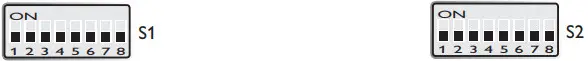
S1 DIP-switch
 | Not used |
S2 DIP-switch
 | Set status port on local fiber link (FL L) error only. |
 | Set status port on both local fiber link (FL L) and remote fiber link (FLR) errors. |
 | Multidrop mid-unit or redundant ring member. |
 | Point to point or multidrop end unit, e.g. the first or last hit in a multidrop network. |
 | Redundant ring focal point. Only one focal point is allowed in a ring. |
Factory settings
Point-to-Point Configuration
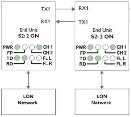
Prepare the Fibre Optical Network
- Both units must be configured for point-to-point application by setting DIP-switch S2:2 to the ON position.
- Set DIP-switch and S2:1 as desired. See the page with “Status port” for more information.
- Verify that DIP-switch S2:3 is in the OFF position.
- Connect the fiber pairs between the units. Always connect CH 1 as shown in the picture above.
- Connect the power supply to all units and verify that all fiber links become active. (CH 1 on both units is on, FL L off).
- Connect the LON devices to the corresponding LRW-702-F2 unit.
- The network is now up and running.
![]() PROCESSING DELAYS
PROCESSING DELAYS
In an LRW-70-F2 fiber-optic network, there will be some additional processing delays that do not exist in an electrical bus. It is possible that the application must be adjusted to accommodate these delays if using many LRW-702-F2 units in a large network. See the page with “Calculating system delay” for more information on how to determine the overall system delay time.
Multidrop Configuration
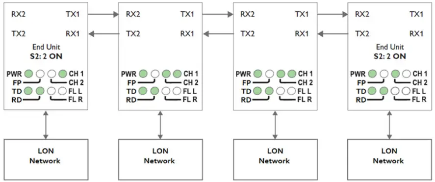
Prepare the Fibre Optical Network
- The first and last LRW-702-F2 units must be configured as Multidrop end units by settting DIP-switch S2:2 to the ON position. (End units only have one fiber pair each and must know that this is a fact)
- Set DIP-switch and S2:1 as desired. See the page with “Status port” for more information.
- Verify that DIP-switch S2:3 is in the OFF position.
- Connect the fiber pairs between the units. Always connect CH 1 from one unit to CH 2 on the next unit as shown in the picture above.
- Connect the power supply to all units and verify that all fiber links become active. (CH 1 and CH 2 LEDs are on, FL L and FL R LEDs are off).
- Connect the LON devices to the corresponding LRW-702-F2 unit.
- The network is now up and running.
![]() PROCESSING DELAYS
PROCESSING DELAYS
In an LRW-70-F2 fiber-optic network, there will be some additional processing delays that do not exist in an electrical bus. It is possible that the application must be adjusted to accommodate these delays if using many LRW-702-F2 units in a large network. See the page with “Calculating system delay” for more information on how to determine the overall system delay time.
Behavior During Optical Link Failure
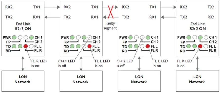
If an optical fiber segment fails, all communication with units beyond the faulty fiber segment will be lost. To determine which fiber segment has failed, look at the FL L, CH 1, and CH 2 LEDs as shown in the picture above.
Redundant Ring Configuration
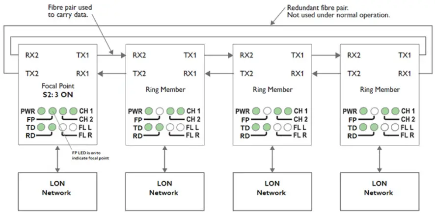
Prepare the Fibre Optical Network
- One, and only one, of the LRW-702-F2 units, must be configured as a ring focal point by setting DIP-switch S2:3 to the ON position. (The ring focal point acts as a logical endpoint in the optical fiber ring, thus forming a bus type of structure)
- Connect the fiber pairs between the units. Always connect CH 1 from one unit to CH 2 on the next unit as shown in the picture above.
- Connect the power supply to all units and verify that all fiber links become active. (CH 1 and CH 2 LEDs are on, FL L and FL R LEDs are off).
- Connect the LON devices to the corresponding LRW-702-F2 unit.
- The network is now up and running.
Note: In an LRW-702-F2 fiber-optic network there will be some additional processing delays that do not exist in an electrical bus. It is possible that the application must be adjusted to accommodate these delays if using many LRW-702-F2 units in a large network.
See the page with “Calculating system delay” for more information on how to determine the overall system delay time.
Behavior During Optical Link Failure
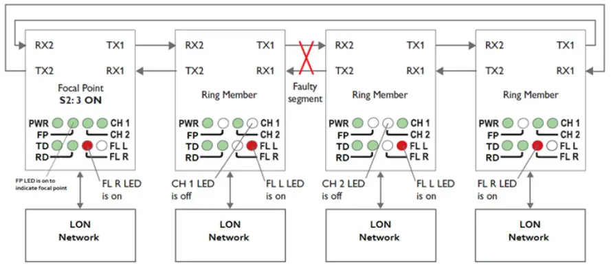
If an optical fiber segment fails, the LRW-702-F2 unit configured as the focal point will reconfigure the system so that data is sent and received over the otherwise redundant fiber pair.
To determine which fiber segment has failed, look at the FL L, CH 1, and CH 2 LEDs as shown in the picture above.
![]() IN CASE OF FIBRE LINK FAILURE
IN CASE OF FIBRE LINK FAILURE
If a fiber link fails, there will be some time before the system reconfigures itself during which data may be corrupted or lost. See “Reconfiguration time under faulty condition” for more information on how to determine the system reconfiguration time.
Calculating System Delay
Data exchange between LONWORKS devices via an LRW-702-F2 fiber optic link will be delayed due to the length of the optical fiber and the signal processing within the LRW702-F2 units. The following equation can be used to calculate the overall system delay:
Maximum delay (µs) = Total fibre distance (m) / 200 + Number of LRW-702-F2 units
For example, in a multidrop system comprising four LRW-702-F2 units connected together using three 1,5 km fiber links, the end to end delay will be: 3 x 1500 / 200 + 4 = 26,5 µs
Reconfiguration Time under Faulty Condition
The reconfiguration time is determined by the time it takes to detect a faulty fibre segment plus the time it takes to transport an error status message through to the LRW-702-F2 focal point unit. The time to transport an error status message to the focal point unit is dependent on how many units the error status message has to be repeated through and the total fiber length delay. The following equation can be used to calculate the reconfiguration time:
Reconfiguration time (µs) = Total fibre distance (m) / 200 + Number of LRW-702-F2 units + 3µs
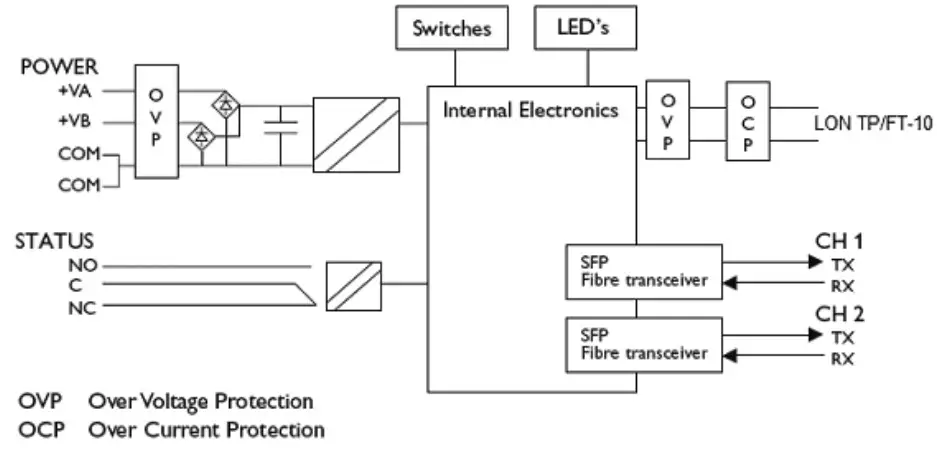
About the Interfaces
Power
The power terminal has two independent inputs, +VA and +VB, allowing redundant power input. The LRW-702-F2 power supply is galvanically isolated from all other interfaces.
Optical Fibre Interfaces
LRW-702-F2 uses Small Form Factor Pluggable (SFP) transceivers. This means that a wide range of different fiber transceivers and connectors can be used.
LONWORKS TP/FT-10 Interface
Connection terminal to a LONWORKS TP/FT-10 transceiver. TP/FT-10 is a twisted pair of communications at 78 kbps with distances to 2700 meters in a doubly terminated
bus topology. The TP/FT-10 also supports free-topology wiring to 500 meters which eliminates the need to install an exact multi-drop arrangement. Star, home run, multidrop, and loop wiring, or any combination, are supported by the TP/FT-10.
Status Port
The status port connects to an internal solid-state relay which may be used to trigger an external alarm if a fault condition occurs. During normal operation pins, 1 and 2 are in
contact with each other. During an optical link failure or power failure, pins 1 and 2 are isolated from each other.
Optical link failures can be classified into two categories, local or remote, as indicated by the FL L and FL R LEDs. A local link failure is when an optical link is down at this particular unit. A remote link failure is when an optical link is down at some other unit.
From the factory, the status port is set to trigger both types of link failures. However, by setting DIP-switch S2:1 to the ON position, the status port will only trigger when a local link failure has occurred.
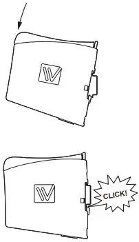
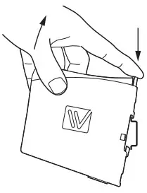
Mounting
This unit should be mounted on a 35 mm DIN-rail, which is horizontally mounted inside an apparatus cabinet, or similar. Snap-on mounting, see figure.
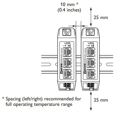
Cooling
This unit uses convection cooling. To avoid obstructing the airflow around the unit, use the following spacing rules. Minimum spacing 25 mm (1.0 inch) above /below and 10 mm (0.4 inches) left /right the unit. Spacing is recommended for the use of the unit in the full operating temperature range and service life.
Removal
Press down the black support at the top of the unit. See figure.
![]()
Westermo • Metallverksgatan 6, SE-721 30 Västerås, Sweden
Tel +46 16 42 80 00 Fax +46 16 42 80 01
E-mail: [email protected]
www.westermo.com


