![]()

MDW-45
Converter
RS-232 – RS-422/485
General information
Legal information
The contents of this document are provided “as is”. Except as required by applicable law, no warranties of any kind, either express or implied, including, but not limited to, the implied warranties of merchantability and fitness for a particular purpose, are made in relation to the accuracy and reliability or contents of this document. Westermo reserves the right to revise this document or withdraw it at any time without prior notice.
Under no circumstances shall Westermo be responsible for any loss of data or income or any special, incidental, and consequential or indirect damages howsoever caused.
More information about Westermo can be found at www.westermo.com
Safety and Regulations
Warning signs are provided to prevent personal injury and/or damages to the product.
The following levels are used:
| Level of warning | Description | Consequence personal injury | Consequence material damage |
| Indicates a potentially hazardous situation | Possible death or major injury | Major damage to the product | |
CAUTION | Indicates a potentially hazardous situation | Minor or moderate injury | Moderate damage to the product |
NOTICE | Provides information in order to avoid misuse of the product, confusion or misunderstanding | No personal injury | Minor damage to the product |
NOTE | Used for highlighting general, but important information | No personal injury | Minor damage to the product |
Before installation:
Read this manual completely and gather all information on the product. Make sure that you understand it fully. Check that your application does not exceed the safe operating
specifications for this product.
![]() WARNING – SAFETY DURING INSTALLATION
WARNING – SAFETY DURING INSTALLATION
The product must be installed by qualified service personnel and built in to an apparatus cabinet or similar, where access isrestricted to service personnel only.![]() WARNING – HAZARDOUS VOLTAGE
WARNING – HAZARDOUS VOLTAGE
Do not open an energized product. Hazardous voltage may occur when connected to a power supply.![]() WARNING – PROTECTIVE FUSE
WARNING – PROTECTIVE FUSE
The power supply wiring must be sufficiently fused.
It must be possible to disconnect manually from the power supply.
Ensure compliance to national installation regulations. CAUTION – ELECTROSTATIC DISCHARGE (ESD)
Prevent electrostatic discharge damages to internal electronic parts by discharging your body to a grounding point (e.g. use a wrist strap).
Product disposal
![]() This symbol means that the product shall not be treated as unsorted municipal waste when disposing of it. It needs to be handed over to an applicable collection point for recycling electrical and electronic equipment.
This symbol means that the product shall not be treated as unsorted municipal waste when disposing of it. It needs to be handed over to an applicable collection point for recycling electrical and electronic equipment.
By ensuring this product is disposed of correctly, you will help to reduce hazardous substances and prevent potential negative consequences to both environment and human
health, which could be caused by inappropriate disposal.
Care recommendations
Follow the care recommendations below to maintain full operation of product and to fulfill the warranty obligations:
- Do not drop, knock or shake the product. Rough handling above the specification may cause damage to internal circuit boards.
- Use a dry or slightly water-damp cloth to clean the product. Do not use harsh chemicals, cleaning solvents or strong detergents.
- Do not paint the product. Paint can clog the product and prevent proper operation.
If the product is used in a manner not according to specification, the protection provided by the equipment may be impaired.
If the product is not working properly, contact the place of purchase, nearest Westermo distributor office or Westermo technical support.
Declaration of Conformity
Hereby, Westermo declares that this product is in compliance with applicable EU directives and UK legislations. The full declaration of conformity and other detailed information is available at www.westermo.com/support/product-support.

Agency approvals and standards compliance
| Type | Approval / Compliance | |
| EMC | EN 61000-6-2 | Immunity industrial environments |
| EN 61000-6-4 | Emission industrial environments | |
FCC Part 15.105 Notice:
This equipment has been tested and found to comply with the limits for a Class B digital device, pursuant to Part 15 of the FCC Rules. These limits are designed to provide reasonable protection against harmful interference in a residential installation. This equipment generates, uses and can radiate radio frequency energy and, if not installed and used in accordance with the instructions, may cause harmful interference to radio communications. However, there is no guarantee that interference will not occur in a particular installation. If this equipment does cause harmful interference to radio or television reception, which can be determined by turning the equipment off and on, the user is encouraged to try to correct the interference by one or more of the following measures:
- Reorient or relocate the receiving antenna.
- Increase the separation between the equipment and receiver.
- Connect the equipment into an outlet on a circuit different from that to which the receiver is connected.
- Consult the dealer or an experienced radio/TV technician for help.
Type tests and environmental conditions
| Electromagnetic Compatibility | |||
| Phenomena | Test | Description | Level |
| ESD | EN 61000-4-2 | Enclosure contact | ± 6 kV |
| Enclosure air | ± 8 kV | ||
| RF field AM modulated | IEC 61000-4-3 | Enclosure | 10 V/m 80% AM (1 kHz), 80 – 1 000 MHz 20 V/m 80% AM (1 kHz), 800 – 960 MHz 20 V/m 80% AM (1 kHz), 1 400 – 2 700 MHz |
| Fast transient | EN 61000-4-4 | Signal ports | ± 2 kV |
| Power ports | ± 2 kV | ||
| Surge | EN 61000-4-5 | Signal ports unbalanced | ± 2 kV line to earth, ± 2 kV line to line |
| Signal ports balanced | ± 2 kV line to earth, ± 1 kV line to line | ||
| Power ports | ± 2 kV line to earth, ± 2 kV line to line | ||
| RF conducted | EN 61000-4-6 | Signal ports | 10 V 80% AM (1 kHz), 0.15 – 80 MHz |
| Power ports | 10 V 80% AM (1 kHz), 0.15 – 80 MHz | ||
| Magnetic field, power freq. | EN 61000-4-8 | Enclosure | 100 A/m, 50 Hz, 16.7 Hz & 0 Hz |
| Pulse Magnetic field | EN 61000-4-9 | Enclosure | 300 A/m, 6.4 / 16 ms pulse |
| Mains freq. 50 Hz | EN 61000-4-16 | Signal ports | 100 V 50 Hz |
| Mains freq. 50 Hz | SS 436 15 03 | Signal ports | 250 V 50 Hz |
| Radiated emission | CISPR 22 | Enclosure | Class B |
| FCC part 15 | Class B | ||
| Conducted emission | CISPR 22 | AC power ports | Class B |
| FCC part 15 | AC power ports | Class B | |
| CISPR 22 | DC power ports | Class B | |
| Dielectric strength | Signal port to all other | 2 kVrms 50 Hz 1min | |
| Power port to all other | 3 kVrms 50 Hz 1min 2 kVrms 50 Hz 1min (@ rated power < 60V) | ||
| Environmental | |||
| Temperature | Operating | -40 to +70°C | |
| Storage & Transport | -40 to +70°C | ||
| Humidity | Operating | 5 to 95% relative humidity | |
| Storage & Transport | 5 to 95% relative humidity | ||
| Altitude | Operating | 2 000 m / 70 kPa | |
| Service life | Operating | 10 year | |
| Vibration | IEC 60068-2-6 | Operating | 7.5 mm, 5 – 8 Hz 2 g, 8 – 500 Hz |
| Shock | IEC 60068-2-27 | Operating | 15 g, 11 ms |
| Packaging | |||
| Enclosure, MDW-45 | UL 94 | PC / ABS | Flammability class V-1 |
| Dimension W x H x D | 35 x 121 x 119 mm | ||
| Weight | 0.19 kg | ||
| Degree of protection | IEC 529 | Enclosure | IP 21 |
| Cooling | Convection | ||
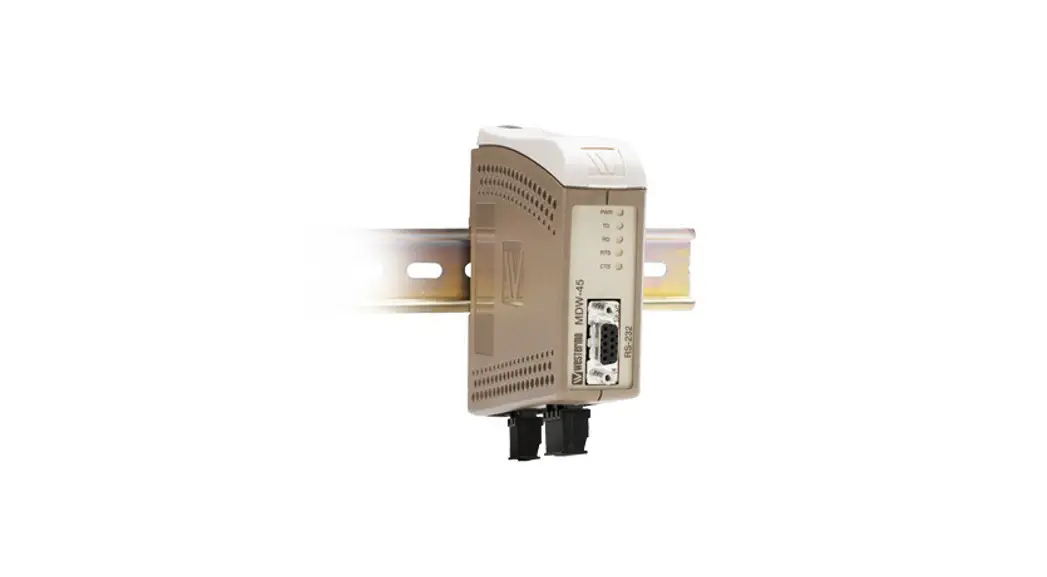
| Mounting | Horizontal on 35 mm DIN-rail | ||
Functional description
The MDW-45 is an RS-422/485 to RS-232 converter. This device can be used in multidrop and point to point applications to connect devices like PCs, PLCs, drives and other automation equipment. In 2-wire half duplex applications (RS-485) the MDW-45 can automatically control the state of the data bus based just on the data it receives. This allows the unit to be used with equipment that has no handshaking signal. The maximum transmission rate possible is 115.2 kbit/s.
Interface specifications
| Power | ||
| MDW-45 LV | MDW-45 HV | |
| Rated voltage | 12 to 48 VDC | 95 to 240 VAC 110 to 250 VDC |
| Operating voltage | 9.6 to 57.6 VDC | 85.5 to 264 VAC 88 to 300 VDC |
| Rated current | 95 mA @ 12 VDC 35 mA @ 48 VDC | 21 mA @ 95 VAC 10 mA @ 110 VDC |
| Rated frequency | DC | 48 – 62 Hz / DC |
| Polarity | Reverse polarity protected | Polarity independent |
| Connection | Detachable screw terminal | Detachable screw terminal |
| Connector size | 0.2 – 2.5 mm² (AWG 24-12) | 0.2 – 2.5 mm² (AWG 24-12) |
| RS-422/485 | |
| Electrical specification | RS-485 |
| Data rate | 1 200 bit/s – 115.2 kbit/s |
| Data format | 7 or 8 data bit, Odd, even or none parity, 1 or 2 stop bit |
| Connection | Detachable screw terminal |
| Connector size | 0.2 – 2.5 mm² (AWG 24-12) |
| Transmission range | In accordance with EIA RS-485 ≤ 1200 m, depending on data rate and cable type |
| Settings | 120 Ω termination and failsafe biasing 680 Ω , by DIP-switch |
| Protection | Installation Fault Tolerant (up to ±60 V) |
| RS-232 | |
| Electrical specification | RS-232 |
| Data rate | 1 200 bit/s – 115.2 kbit/s |
| Data format | 7 or 8 data bit, Odd, even or none parity, 1 or 2 stop bit |
| Connection | 9-pin D-sub female DCE |
| Transmission range | 15 m |
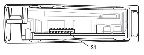
Locations of Interface ports, LED`s and DIP-switches
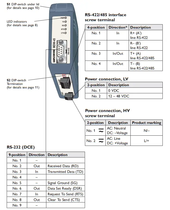
Railway installation close to the rails (RS-232, RS-422/485)
For a cable located inside 3 m boundary and connected to this port, the use of shielded cable is recommended, this to minimize the risk of interference. The cable shield should be properly connected (360°) to an earthing point within 1 m from this port. This earthing point should have a low impedance connection to the conductive enclosure of the apparatus cabinet, or similar, where the unit is built-in. This conductive enclosure should be connected to the earthing system of an installation and may be directly connected to the protective earth.
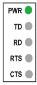
LED Indicators
| LED | Status | Description |
|
| PWR | ON | In service | |
| OFF | Out of service | ||
| TD | ON | Transmitted Data: Displays data received from the local RS-232 port | |
| OFF | No data | ||
| RD | ON | Received Data: Displays data leaving the modem on the RS-232 port | |
| OFF | No data | ||
| RTS | ON | Status of RTS from the RS-232 interface | |
| OFF | No RTS | ||
| CTS | ON | Status of CTS from the RS-232 interface | |
| OFF | No CTS |
DIP-switch settings![]() Before DIP-switch settings:
Before DIP-switch settings:
Prevent damage to internal electronics from electrostatic discharges (ESD) by discharging your body to a grounding point (e.g. use of wrist strap).
S2 Below panel, RS-422/485 termination
 No termination and fail-safe
 Termination with fail-safe (2-wire)
 Termination with fail-safe (4-wire)
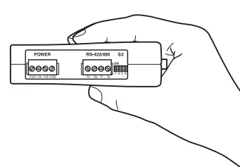
Note! DIP-switch alterations are only effective after a power on.
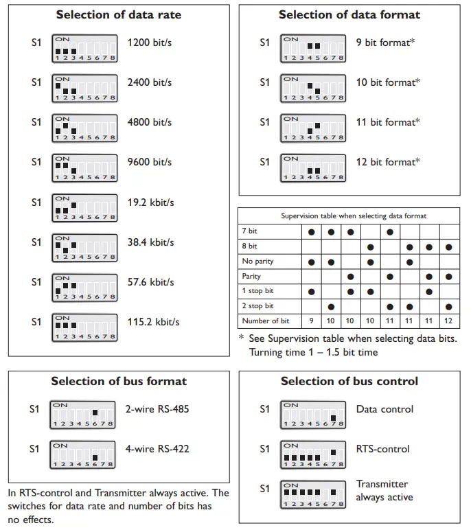
Factory settings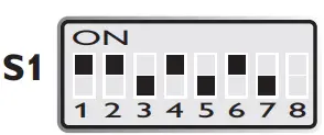 Data rate – 9600 bit/s, data format – 10 bitBus format, 2-wire
Note: Switch 1:8 is not used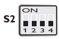 No termination and fail-safe
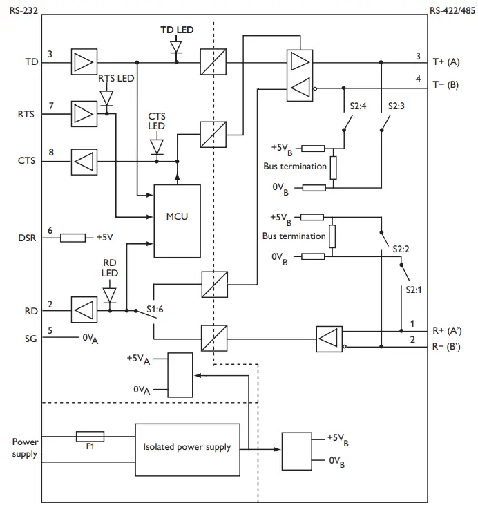
Unit specific description
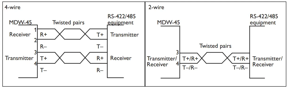
When the converter is set to data-control mode the transmitter is activated by data on TD (RS-232).The time the transmitter stays active corresponds to one character-time plus the turning time for the set data rate and number of bits. If more data arrives on TD before the turning time has expired the transmitter stays active for an additional one character time and so on. In RTS-control mode the transmitter is activated by the RS-232 RTS-signal. In this mode the dip-switches for data rate and number of bits have no effect. The LED indicators show the status of the data signals. The fail-safe termination ensures that the signal level at the receiver is in ‘mark state’ (differential>0.2 Volts) when there is no data on the RS-485 bus. Full duplex is only possible if 4-wires are used.
Field of application
RS-422 and RS-485 were both designed for multidrop applications. When a system is installed it should always form a bus structure (see diagrams). Star shaped networks should never be created; there are other Westermo products that can be used to create star net applications. To install a system according to the RS-422/485 specification it is
very important that the line is terminated at the correct points. The recommendation is to terminate the receiver on the master unit and the final bus slave unit. See diagrams for details of how this is done with RS-485 (2-wire) and RS-422 (4-wire).
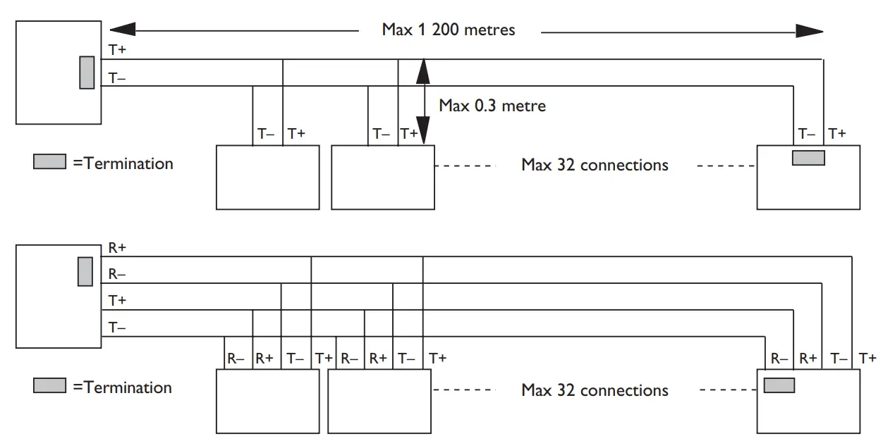
N.B. R+/R–, T+/T– definitions are not standard, it can help to shift + and – if the unit does not work.
Line connection
![]() Westermo • Metallverksgatan 6, SE-721 30 Västerås, Sweden
Westermo • Metallverksgatan 6, SE-721 30 Västerås, Sweden
Tel +46 16 42 80 00 Fax +46 16 42 80 01
E-mail: [email protected]
www.westermo.com


