![]()
![]()
Installation Instructions
Document No. 129-140
April 5, 2022
Retrostat Kits for Honeywell D/N or H/C Thermostats
Product Description
The Retrostat kits convert a Honeywell day/night or heating/cooling pneumatic thermostat to a POWERS™ Controls direct or reverse acting, twopipe, dual temperature pneumatic device.
Contents
| Part | Quantity |
| Retrostat Cover Kit | 1 |
| Thermostat * | 1 |
| Adapter frame | 1 |
| Bag assembly with installation hardware | 1 |
* Includes thermostat installation instructions. 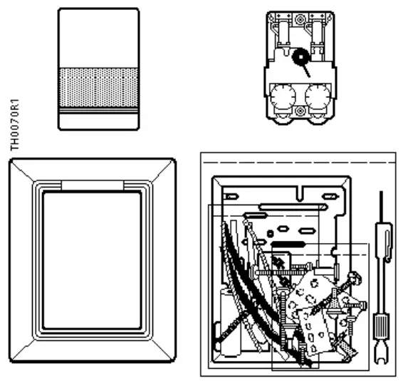
Product Number
| Retrostat Kit (See Note) | Honeywell Product | ||
| Number | Type | Action | |
| 194-3042 | TP971A1003 TP971A1029 TP971A1037 TP971A1045 TP971A1086 | Day/ Night | Direct/ Direct |
| 194-3142 | Same as above with Celsius scale | ||
| 194-3082 | TP972A1002 TP972A1028 TP972A1036 TP972A1101 | Heating/ Cooling | Direct/ Reverse |
Expected Installation Time
1 hour
Prerequisites
- Review all of these instructions before you begin installation.
- Check job drawings for any site-specific information.
- Verify the existing thermostat installation has its supply and return air lines connected properly.
NOTE: Supply is the Powers term for main air and Return is the term for branch air. - Obtain the installation instructions provided with the thermostat in this Retrostat Kit. The document provides instructions for calibrating the thermostat.
- Make certain a supply of wall anchors and plastic ties are available.
Specifications
| Operating range | 45 to 85°F (7 to 30°C) |
| Air supply pressure | |
| Day/Cooling | |
| Minimum | 10 psi (69 kPa) |
| Maximum | 13 psi (90 kPa) |
| Night/Heating | |
| Minimum | 18 psi (124 kPa) |
| Maximum | 30 psi (207 kPa) |
| Sensitivity adjustment | 1 to 4 psi/°F (12 to 50 kPa/°C) |
| Temperature response | 0.1°F (0.06°C) |
| Storage temperature | 10 to 140°F (–23 to 60°C) |
| Dial graduations | 2°F (1°C) |
| Factory settings (adjustable) | |
| Temperature | 72°F (22°C) |
| Sensitivity | 2.5 psi/°F (31 kPa/°C) |
| Limit stops | 45 and 85°F (7 and 30°C) |
Required Tools
- Calibration and cover screw wrench (192-632) or 1/16” Allen wrench and 1/8” open-end wrench
- Medium flat blade screwdriver
- Small level
- Accurate thermometer
- Needle nose pliers
Installation
Removing Existing Thermostat
- Remove the existing thermostat from the wall.
- Plug the supply (main) air line.
- Place a piece of tape on the supply air line to identify it.
- Remove the terminal head and the gasket from the fitting.
- Clean the surface of the fitting, if required.
Installing New Thermostat
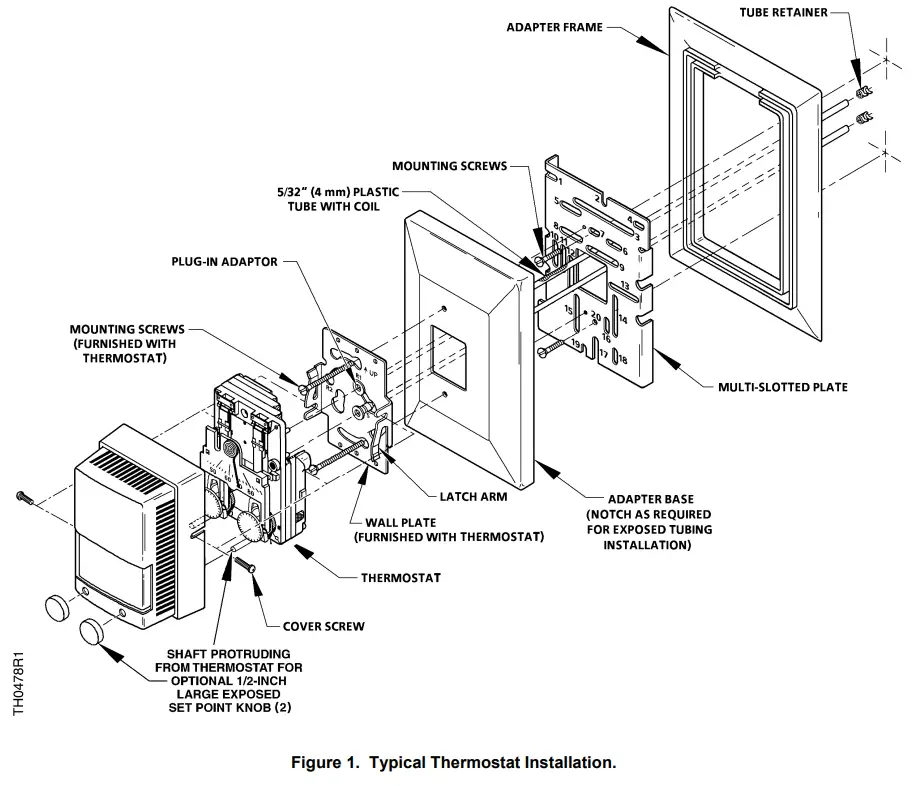
See Figure 1 for a typical thermostat installation.
- The following table lists the figures that correspond to a particular thermostat application. See the appropriate figure to identify the mounting parts.
Honeywell Thermostat Type Type of Terminal FigureNumber TP901A, B Flush Fitting 2 Plaster Back 3 HO, HP, TO, TP, TRO900 Surface Box 4 Flush Box 5 TP931 Flush Electrical Box 6 TP970 to TP974 Shallow Wall Box with Plaster Ring 7 Deep Wall Box 8 TP410, TP910, to TP924, TP933 Flush Banjo 9 Mortar Joint 10 TP901C Mullion or Partition 11 Terminal Head Removed 1/8-inch O.D. Copper Tubing 12 3/16-inch O.D. Copper Tubing 13 - Complete the required air line connections as necessary. Secure all connections and install the plug-in adapters into the 5/32-inch (4 mm) plastic tube. Use the blue adapter for the supply air line. See Figure 1.
NOTE: Either polyethylene (hard, black) or polyurethane (soft, clear) tubing is recommended. The appropriate tubing depends on which is most compatible for the application. - Place the multi-slotted metal plate into the adapter frame, if required. Attach the multislotted plate to the terminal head or the wall using screws and slots shown in Figures 2 through 13.
- Loosely screw adapter base to the multi-slotted plate.
- Draw plastic tubing through the multi-slotted plate and the adapter base. Install the plug-in adapters on the wall plate.
- Using mounting screws supplied with the thermostat chassis, install the wall plate on the adapter base as follows:
a. Guide screws through the slotted key holes on the wall plate and partially insert them into the adapter base.
b. Orient the wall plate so that it is square and level.
c. Tighten the mounting screws to secure the wall plate in place. - Moisten the thermostat supply and return ports to lubricate them. Carefully insert the thermostat ports into the terminal adapter “O” rings on the wall plate.
- Configure the cover per installation instructions provided and mount the cover over the thermostat.
- Use either the hex key end of the calibration and cover screw wrench or a 1/16” Allen wrench to tighten the two screws that secure the cover in place.
NOTES:
1. To remove the thermostat from the wall plate, hold the thermostat firmly at the top and bottom and start to pull the thermostat from the wall plate. At the same time, use a screwdriver to pry the wall plate latch arms away from the thermostat chassis and pull the thermostat away from the wall plate.
Frequent removal and installation of the thermostat can bend the latch arms beyond their operating positions. If this occurs, bend the latch arms back to their operating positions before mounting the thermostat.
The installation is complete.
Calibration, Adjustment, and Troubleshooting
See the installation instructions provided with the thermostat in this retrostat kit for the following procedures:
- Thermometer Calibration
- Changeover Point Adjustment
- Limit Stop Adjustment
- Sensitivity Adjustment
- Thermostat Cooling/Heating Calibration
- Troubleshooting
Reference
Technical Bulletin……………. Document Number
TB 214 TH 192 Adapter Kits………… 155-231
 NOTE: Adapter Base and Plug-In Adapter (2) not shown. See Figure 1 for proper installation.
Figure 2. TP901A, B Flush Fitting.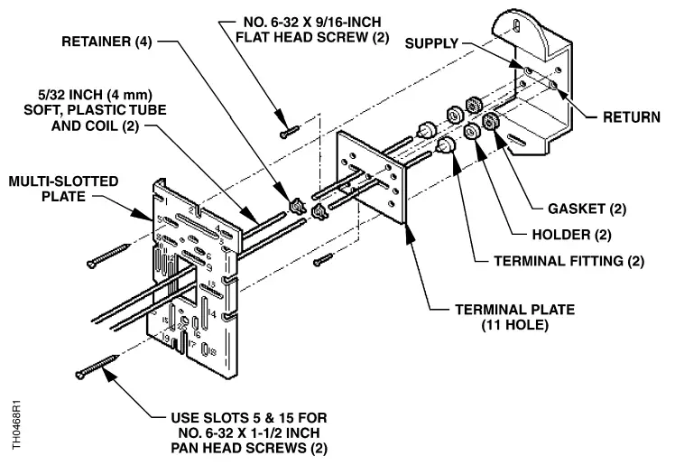 NOTE: Adapter Base and Plug-In Adapter (2) not shown. See Figure 1 for proper installation.
Figure 3. TP901A, B Plaster Back.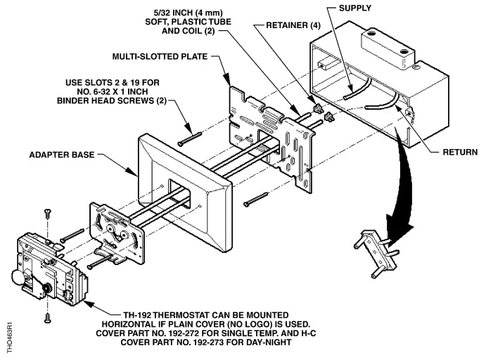 NOTE: Plug-In Adapter (2) not shown. See Figure 1 for proper installation.
Figure 4. HO, HP, TP, TRO900 B Surface Box.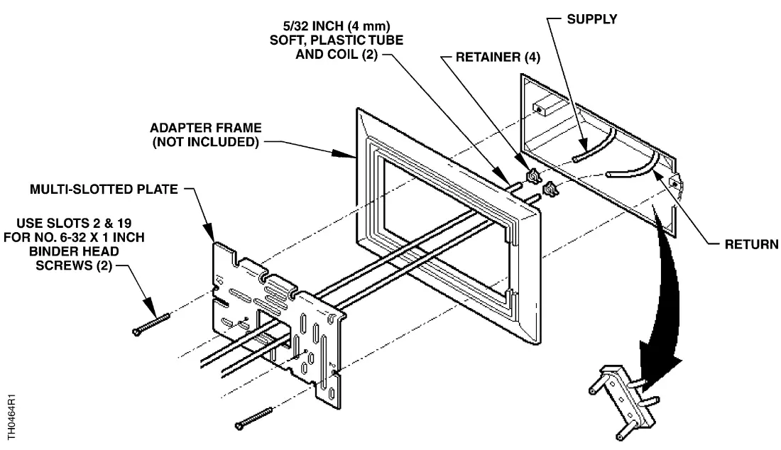
NOTE: Adapter Base and Plug-In Adapter (2) not shown. See Figure 1 for proper installation.
Figure 5. HO, HP, TP, and TRO900 Flush Box.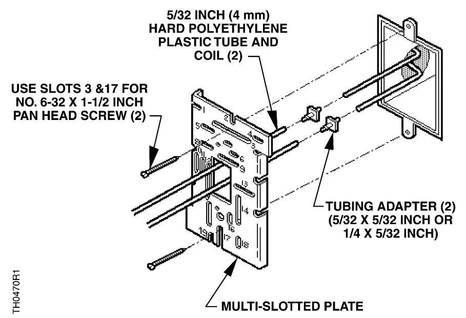
NOTE: Retainer (2), Adapter Base, and Plug-in Adapter (2) not shown. See Figure 1 for proper installation.
Figure 6. TP931 Flush Electrical Box.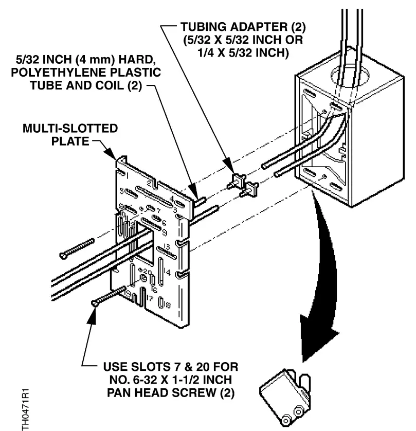 NOTE: Retainer (4), Adapter Base, and Plug-in Adapter (2) not shown. See Figure 1 for proper installation.
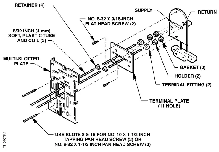
Figure 7. TP970 through TP974 Shallow Wall Box with Plaster Ring.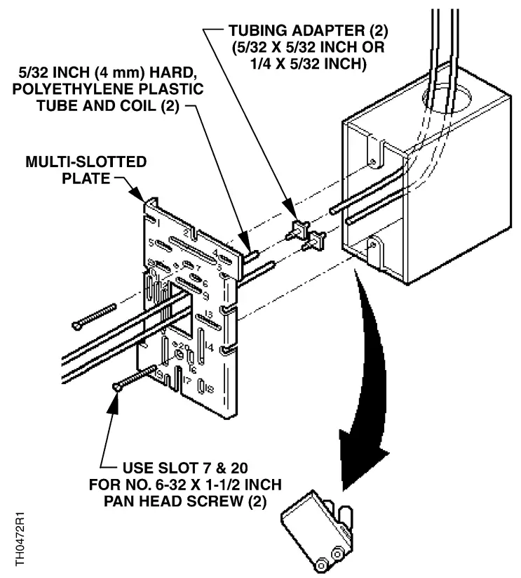 NOTE: Retainer (2), Adapter Base, and Plug-in Adapter (2) not shown. See Figure 1 for proper installation.
Figure 8. TP970 through TP974 Deep Wall Box.
INSERT TUBES INTO “0” RINGS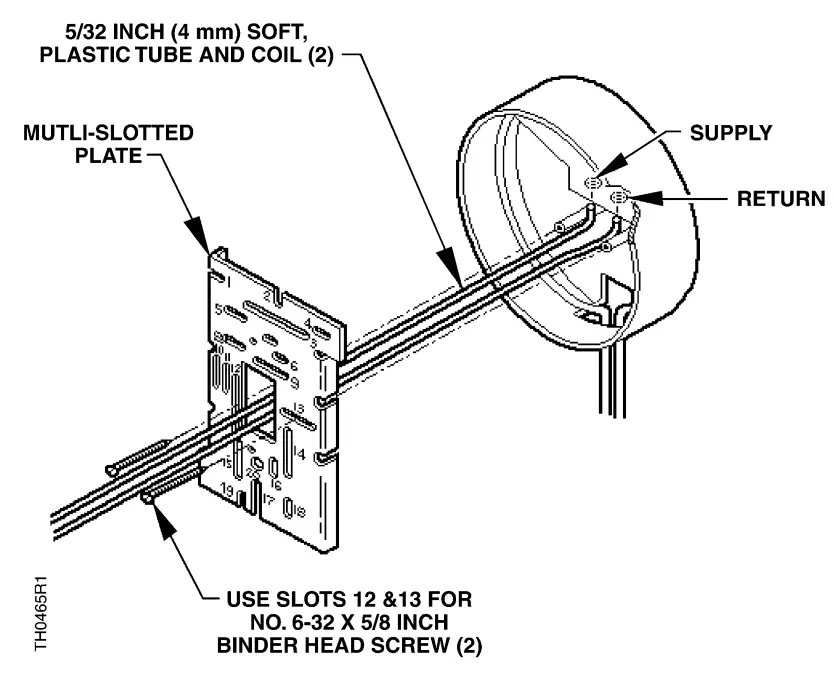
NOTE: Retainer (2), Adapter Base, and Plug-in Adapter (2) not shown. See Figure 1 for proper installation.
Figure 9. TP410, TP910 through TP924, and TP933 Flush Banjo.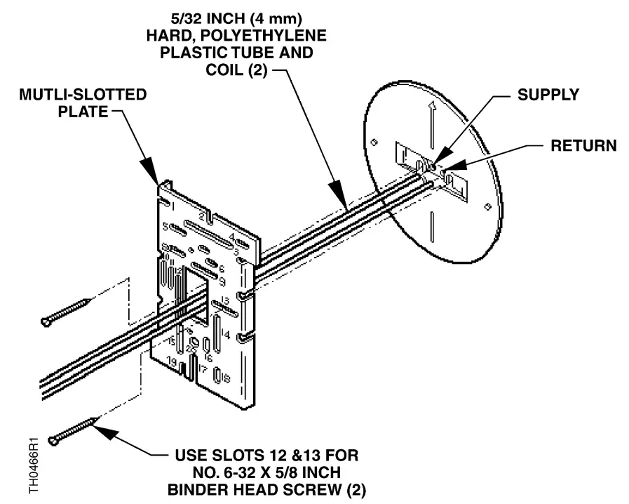 Figure 10. TP410, TP910 through TP924, and TP933 Mortar Joint.
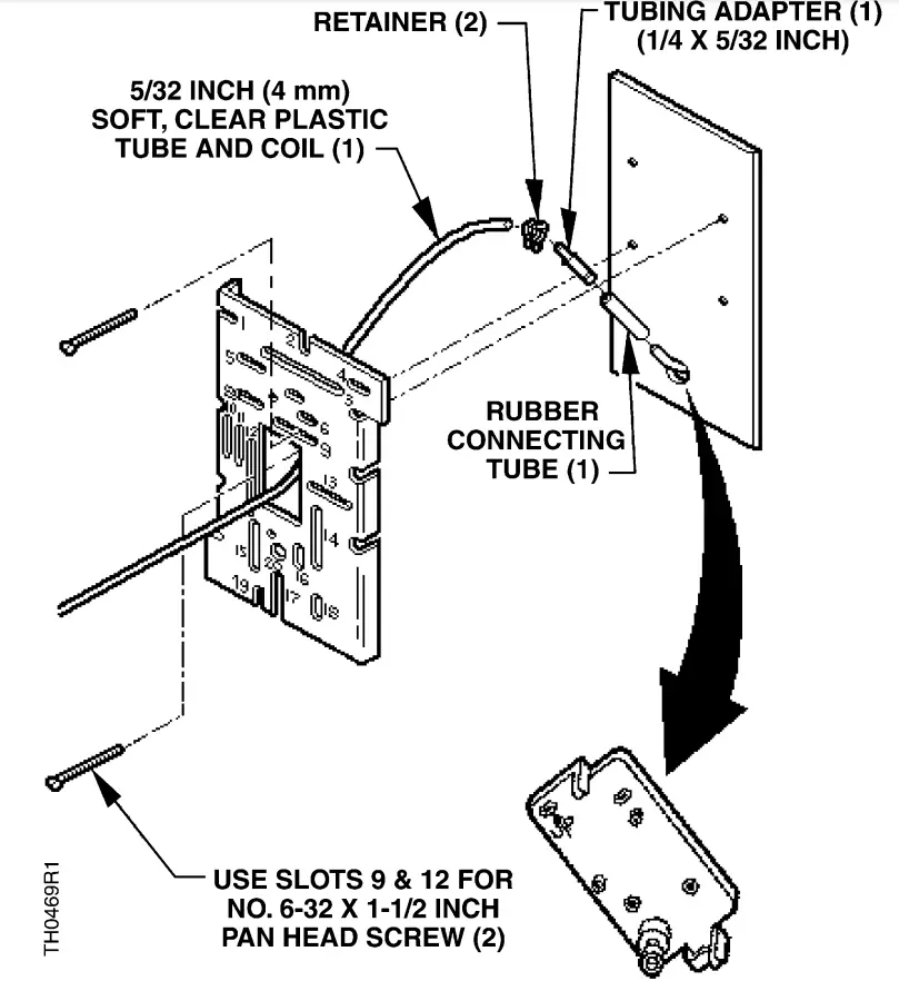 Figure 11. TP901C Mullion or Partition.
 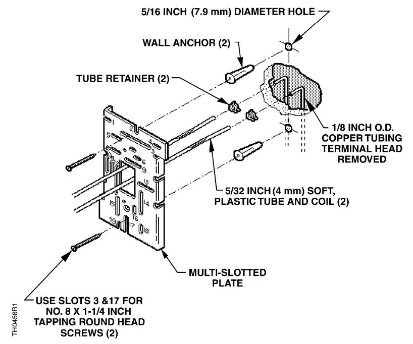 Figure 12. Terminal Head Removed with 1/8-inch O.D. Copper Tubing.
 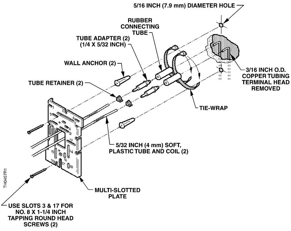 Figure 13. Terminal Head Removed with 3/16-inch O.D. Copper Tubing.
Information in this publication is based on current specifications. The company reserves the right to make changes in specifications and models as design improvements are introduced. Retroline is a registered trademark of Siemens Industry, Inc. Other product or company names mentioned herein may be the trademarks of their respective owners. © 2017-2022 Siemens Industry, Inc.
![]() Siemens Industry, Inc.
Siemens Industry, Inc.
Building Technologies Division
1000 Deerfield Parkway
Buffalo Grove, IL 60089-4513
USA
Tel. +1 847-215-1000
Your feedback is important to us. If you have
comments about this document, please send them
to [email protected]
Document No. 129-140
Printed in the USA


