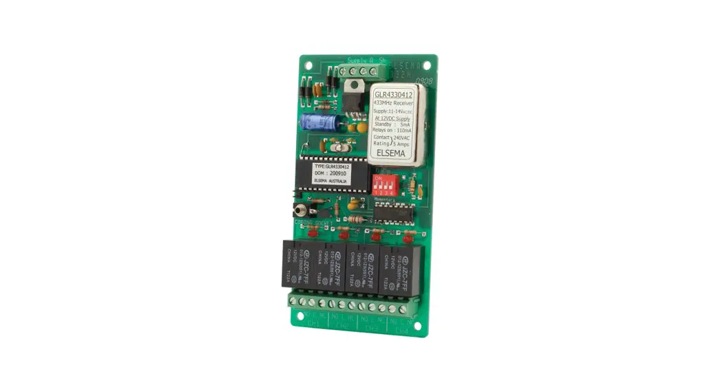
![]() GLR43303, GLR43304 Multi-Channel 433MHz Gigalink Receiver
GLR43303, GLR43304 Multi-Channel 433MHz Gigalink Receiver
User Guide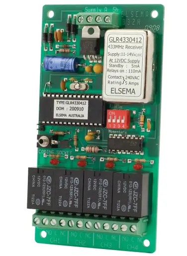
Features
- Supply voltage can be 12 – 24 Volts AC or DC
- Highly sensitive receiver input stage. When used with GLT433…. Series transmitters and an ANT433S antenna, an operating range of 350 metres (980 ft) is possible.
- Three or four relay outputs. All outputs can be operated simultaneously.
- Crystal controlled for high stability and performance.
- Uses micro-controller technology that can be re-programmed to suit unique applications.
- Momentary, latching and security latching output modes are user selectable.
- Power ON LED indicator.
- Test buttons for the relay.
Applications
- Automatic gates, security, timer-controlled outputs, and simple on/off functions
Description
The GIGALINK™ is the most advanced Remote Control technology available in the world today. GIGALINK™ is an invention that has revolutionized the entire Remote Control technology including Elsema’s earlier version of the FMT- … and FMR- … series. The GLR…. series state-of-the-art invention brings a new dimension to the world of Remote Control technology in domestic, commercial, and industrial applications.
The innovative microcontroller technology replaces the traditional dip switch coding which eliminates any possible code grabbing. Special features such as over four billion code combinations, the ability to program any number of transmitters to any of the receiver outputs, four user-selectable modes, dual conversion superhet, and operation over a wide voltage range all add up to the most advanced and secure Remote Control available.
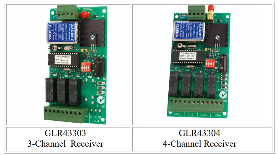
The multi-channel receivers are available with three or four channels.
Four billion codes
The user can easily change the code on all the channels. Momentary joining the two CC pins on the receiver board sets all channels to one random code. One of 4,294,967,296 possibilities is selected.
Code Programming
For code programming, please refer to the separate programming instructions.
The receiver power must be connected when single or channelized code programming. When programming is completed and the GIGALINK cable is removed from the multi-channel receiver-coding socket, the 4-way dip switch is used to select different output modes. This is described below.
Output Modes
Relay output on the receiver can function in either momentary or latching mode. By default, the mode is set to momentary. Modes are selectable from the 4-way dipswitch. Dipswitch 1 corresponds to relay channel 1 and dipswitch 2 corresponds to relay channel 2 and so on.
Factory Default = Momentary
Momentary – Output is active for as long as the transmitter button is pressed.
This is a standard mode on most automatic gates or garage door openers.
Latching – Output remains active until the next press of the transmitter button.
Similar to switching “on” and “off” a light.
Security Latching – Output remains active until power to the receiver is removed. Similar to security alarms and fire alarms. To activate the security latching mode, a link needs to be soldered into the hole marked as latching.
Customized Software
Custom output modes can be programmed to do special functions. Call Elsa for more details.
AC/DC Supply and Antenna
AC/DC power supply and the antenna is connected via a screw-type terminal block. Do not connect the supply to the 2.5mm coding socket since the connection may damage the microcontroller.
Unique Code System
The microcontroller EEPROM allows large volume users to have a unique code. This enables Elsema to offer everyone “your own” radio control. Case The three or four-channel receiver is supplied without a case, this allows the receiver to be integrated according to your needs. Elsa has available a Quick Mount bracket which enables easy mounting to walls, roofs etc.
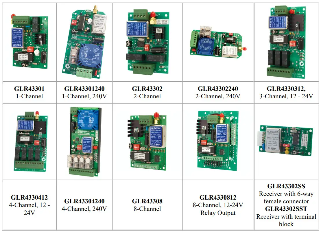
Products in the Range
Technical Data
| Supply Voltage | 12 – 24 Volts AC or DC. Can use Elsema’s AC power pack (12PP-1000) |
| Current Consumption | GLR43303/4: 16mA standby at 12VDC |
| Receiving Freq | 433.920MHz (Other frequencies available on request. Refer to the table below ) |
| Operating Temperature Range | -5 to 50°C |
| Sensitivity | Better than 1.0uV (For output to switch on) |
| Type of Demodulation | Amplitude Shift Keying (ASK) |
| Decoding System | Microcontroller-based 96-bit word |
| Code Combinations | 4,294,967,296 |
| Outputs | GLR43303: Three change-over relay outputs, each rated at 8 Amps/240Volts GLR43304: Four change-over relay outputs, each rated at 8 Amps/240 Volts |
| Connections | Screw-type terminal block. |
| Antenna | Elsa’s ANT433MHz series antennas or pieces of approximately 690 mm long wire for short-range applications. |
| Dimensions | 130 X 70 X 30 mm |
| Mounting hole size | 3.97 mm or 5/32″ |
| Weight | GLR43303: 97 grams GLR43304: 116 grams |
| Microcontroller | Can be re-programmed to suit your customized needs |
| Useable Transmitters | All Elsema Type 433MHz GLT-… series |
Available Frequencies
| SF2 | 433.664 MHz |
| SF3 | 433.408 MHz |
| SF4 | 433.152 MHz |
| SF5 | 434.688MHz |
| SF6 | 434.432 MHz |
Special Frequency products can be made upon request. There is a minimum quantity order of 20. Please quote the Correct SF number when ordering transmitters on special frequencies.
Block Diagram
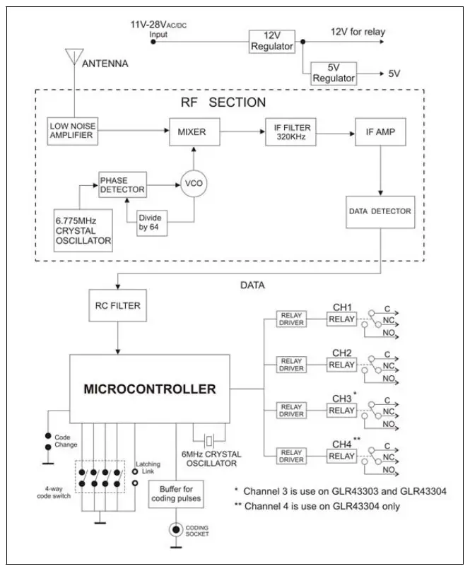 |  |
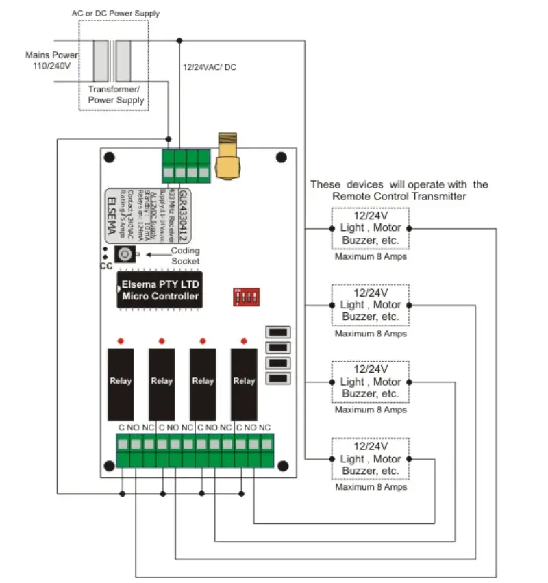 |  |
Manufactured by
Elsema Pty Ltd
31 Tarlington Place, Smithfield
NSW 2164, Australia.
Ph: 02 9609 4668
Website: http://www.elsema.com
Distributed by


