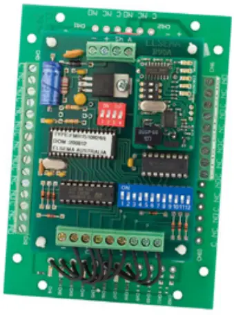
ELSEMA FMR15101 1 Channel 151MHz Receiver User Guide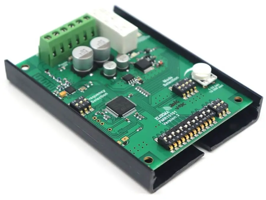
Features
- Single channel receiver with relay output
- Supply voltage can be 12 – 24 Volts AC or DC
- Low current consumption
- Built-in noise or signal strength indicator
- User can select 8 different frequencies
- Easy code setup with dip switch settings
- Momentary, latching, timed and security latching output modes can be selected by the user. Changing the settings on the four-way dip switch does this
- Optional QM100 bracket available for easy mounting to cases or walls. C1015 or C1020 case is also available.
Applications
- Pump Control
- Long distance panic button
- On/Off applications in agricultural devices
- Security alarm
- Basic Telemetry eg. Water level indication
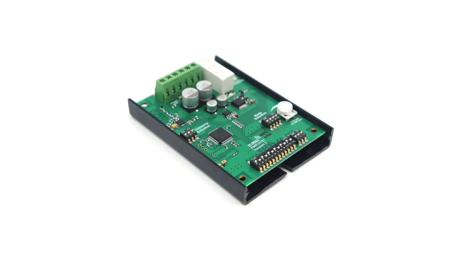
Description
This receiver gives you a single relay output with a contact rating of 8 amps at 240VAC. The relay mode can be set to momentary, latching, security latching, adjustable timed off delays or pulsing.
The user can select 8 different narrow band frequencies and program unlimited number of transmitters to the receiver. With a narrow band FM 151MHz signal from the transmitter a line of sight operating range of 5000 metres is possible. The receiver uses a crystal oscillator circuit that ensures high frequency stability allowing optimal performance in the receiving range.
Coding
The 12 way dip switch on the receiver sets the 12 bit unique code for the system. This has to be matched to that on the transmitter. Do not use the factory default code.
Apart from the 12 way dip switch there will be an additional dip switch depending upon the receiver type:
- Single channel receiver will have a 3 way dip switch.
This DIP switch on the right side of the 12 way dip switch denotes the channel. See table below. Generally to use a 1 channel Tx to 1 channel Rx match all the 15 dip switch (12way + 3way just on the right side of the 12 way).
To use a multi channel Tx to control a number of (up to 8) Rx, refer to the table below for the switch setting.
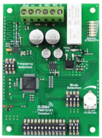
FMR15101
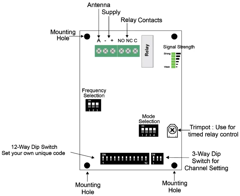
3-Way DIP Switch & Relay Output
| SW13 | SW14 | SW15 | Relay |
| OFF | OFF | OFF | Ch1 |
| OFF | OFF | ON | Ch2 |
| OFF | ON | OFF | Ch3 |
| OFF | ON | ON | Ch4 |
| ON | OFF | OFF | Ch5 |
| ON | OFF | ON | Ch6 |
| ON | ON | OFF | Ch7 |
| ON | ON | ON | Ch8 |
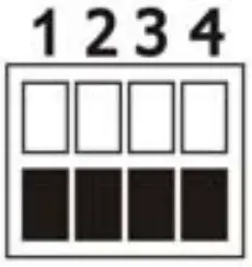
Different Modes for the Output
Modes are user selectable from the 4-way dip switch, shown below.
| “Momentary”: Relay on, only while correct signal is received |
 | “Latching”: Relay alternates at every correct incoming signal |
| “Delayed Off 1”: Relay on, but delayed off for 1-10 seconds, adjustable by trimpot |
 | “Delayed Off 2”: Relay on, but delayed off for 10-300 seconds, adjustable by trimpot |
| “Pulsing”: Relay will pulse at 1Hz for 10-300 seconds, adjustable by trimpot |
 | “Security latching On”: Relay will energize until supply to receiver is momentarily interrupted |
| “On-Off”: This mode requires a 2-channel Tx. Channel 1 will always energize the relay Channel 2 will always de-energize the relay |
 | “Instant OFF ” |
| “Test”: Relay is energized, for test purpose only |


Output Modes
Relay output on the receiver by default the mode is set to momentary. Other modes are selectable from the 4- way dipswitch.
Factory Default = Momentary
Momentary: Output is active for as long as the transmitter button is pressed. This is a standard mode on most automatic gates or garage door openers.
Latching: Output remains active until next press of the transmitter button. Similar to switching “on” and “off” a light.
Security Latching: Output remains active until power to the receiver is removed. Similar to security alarms and fire alarms.
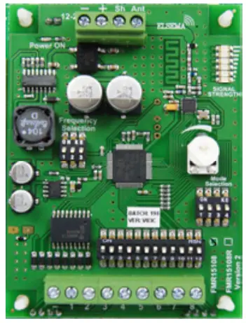
Signal Strength Indicator
The 151MHz receivers have green signal strength LED’s on the board. The table below indicates the level of the valid transmitted signal.
| 6 LED’s on | -70dBm | Very Strong signal | Very Reliable operating conditions |
| 5 LED’s on | -75dBm | Very Strong signal | Very Reliable operating conditions |
| 4 LED’s on | -80dBm | Very Strong signal | Very Reliable operating conditions |
| 3 LED’s on | -90dBm | Strong signal | Very Reliable operating conditions |
| 2 LED on | -100dBm | Good signal | Reliable operating conditions |
Noise Strength Indicator
If more than 2 led is “ON” without a valid transmission, this indicates that there is noise on the frequency selected. Change the 3-way dipswitch on the receiver module to select a different frequency. Following is a table with the Dipswitch settings and the corresponding frequencies.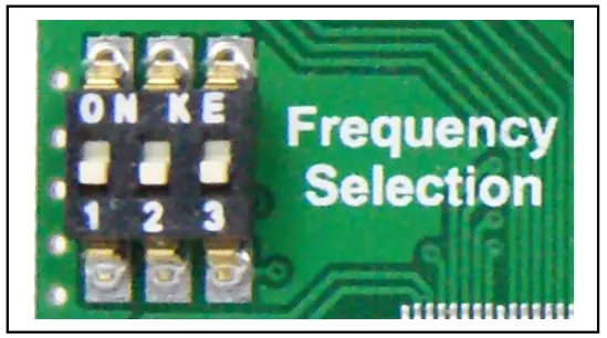
| Frequency | 1 | 2 | 3 |
| 151.600 MHz | On | On | On |
| 152.375 MHz | Off | On | On |
| 151.775 MHz | On | Off | On |
| 151.400 MHz | Off | Off | On |
| 151.175MHz | On | On | Off |
| 151.025 MHz | Off | On | Off |
| 150.900 MHz | On | Off | Off |
| 150.825 MHz | Off | Off | Off |
Technical Data
| Supply Voltage | 12 – 24 Volts AC or DC. Can use Elsema’s power pack (12PP-1000) Supply lines should be less than 3m long to comply with radio frequency authorities | |
| Current Consumption | 24mA Standby at 12VDC | 57mA when relay “ON” at 12VDC |
| Receiving Frequency | 151.6MHz (8 selectable frequencies. See table above) 161MHz for New Zealand 154MHz for United States of America and Canada | |
| Operating Temperature Range | -5 to 50°C | |
| Outputs | One change over relay outputs, rated at 8 Amps 240VAC | |
| Relay Contacts | Common (C), Normally Closed (NC) & Normally Open (NO) | |
| Antenna | 151MHz Antenna, Elsema ANT151M for maximum performance | |
| Dimensions | 95 x 70 x 30mm | |
| Mounting Hole Size | 3.97mm or 5/32” | |
| Useable Transmitters | All FMT151 series (with correct setting on the dip switch). See Transmitter datasheet for details | |
| Useable operating range | Up to 5000 metres, depending on installation and type of antenna used. Recommended Antenna is Elsema ANT151M | |
Products in the Range
- FMR15101 1-Channel

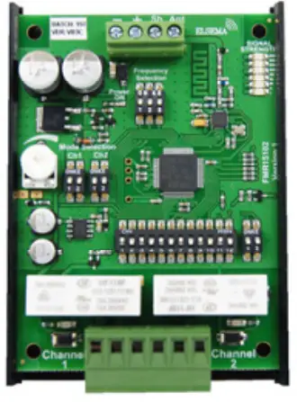
- FMR15102 2-Channel

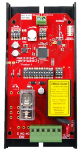
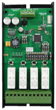
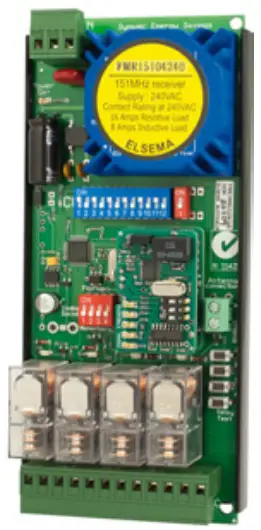
- FMR15101240 1- Channel 240VAC Supply

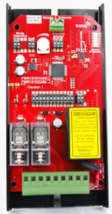
- FMR15102240 2- Channel 240VAC Supply

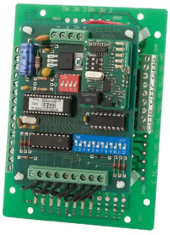
- FMR15104 4-Channel

- FMR15104240 4- Channel 240VAC Supply

- FMR15108 8-Channel

- FMR1510812R 8-Channel, 12V Supply

- FMR1510824R 8-Channel, 24V Supply

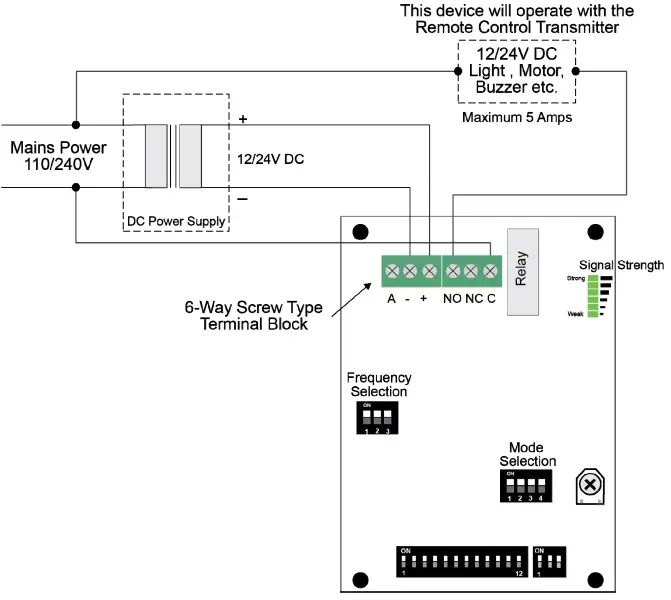
Block Diagram
FMR15101 12/24 VAC/DC Application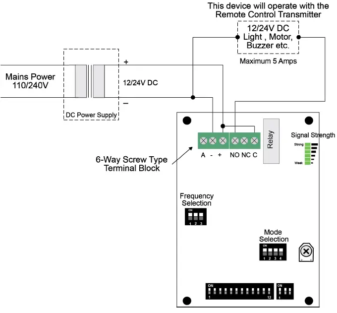
Manufactured by
Elsema Pty Ltd
31 Tarlington Place, Smithfield
NSW 2164, Australia.
Ph: 02 9609 4668
Website: http://www.elsema.com


