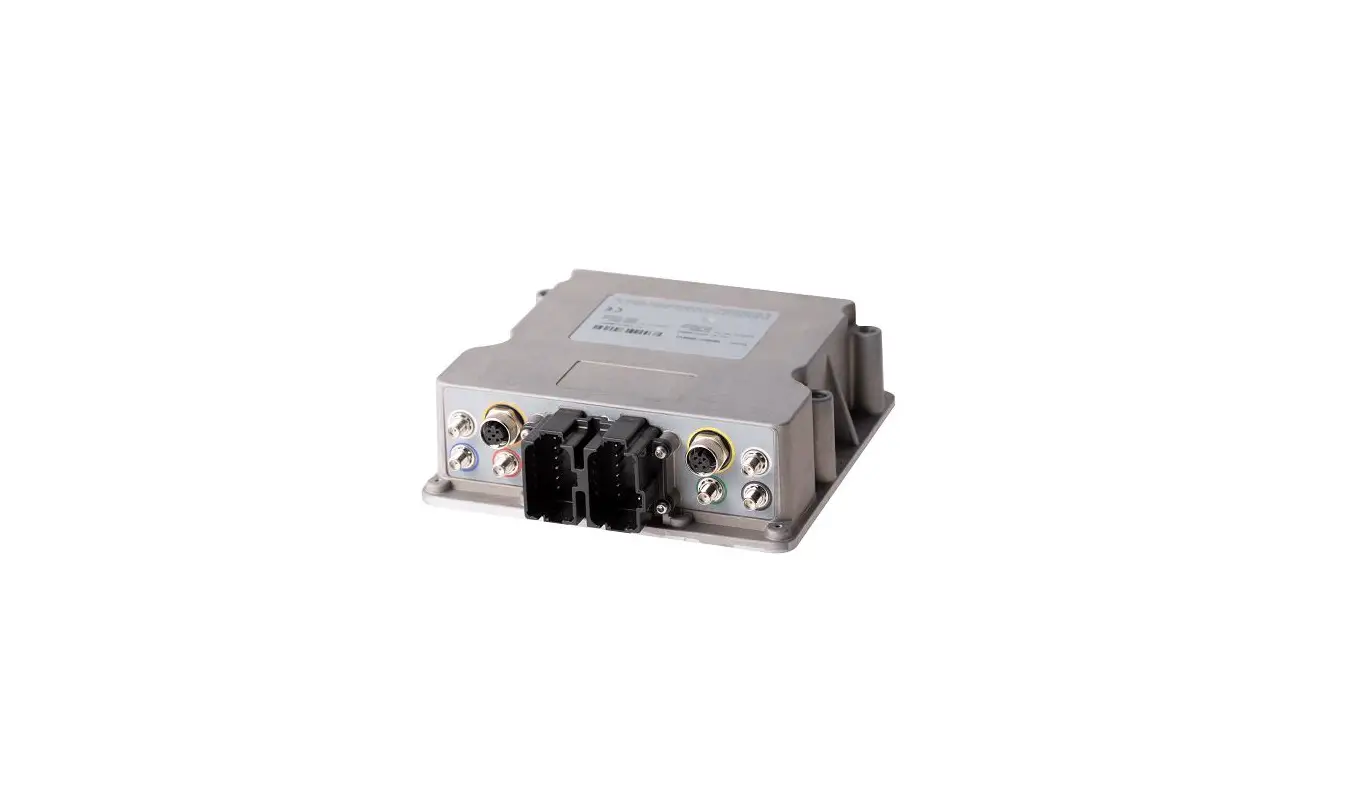
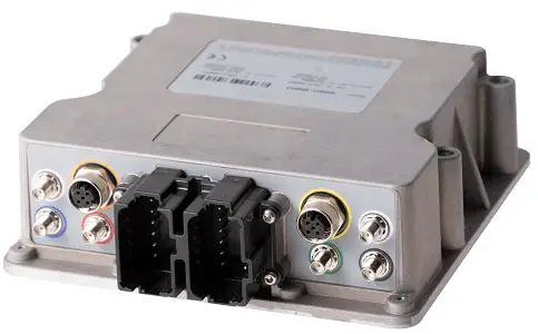
APPAREO 608065 Highly-Capable Rugged Telematics Gateway
Record of Revisions
| Revision Number | Change Description | Effective Date | Inserted By |
| 1.0 | Initial draft | 12/4/18 | Lee Hinsz |
| 1.1 | Addition of model 608065-000040 | 4/2/20 | Lee Hinsz |
| 1.2 | Added ANATEL notification | 7/27/21 | AAL |
| 1.3 | Added model 608065-000043 | 8/19/21 | GJG |
| 2.0 | General clean up, added Gateway 100, added additional cert approvals | 9/29/22 | AAL |
SYSTEM OVERVIEW
Gateways are embedded computers that provide interfacing capability among a variety of wired and wireless networks. Refer to the table below for the specifications of each gateway.
| Name | Model | Cellular | Bluetooth | Wi-Fi | GPS | 433 MHz Radio | Satcom Module | CAN | RS232 | Broad R Reach |
| Gateway 100 | 240433 | x | x | x | x | |||||
| Gateway 260 | 608065- 000034 (Middle Specification) | x | x | x | x | x | x | x | ||
| Gateway 270 | 608065- 000043 (Middle Specification) | x | x | x | x | x | x | x | ||
| Gateway 360 | 608065- 000034 (High Specification) | x | x | x | x | x | x | x | x | x |
| Gateway 370 | 608065- 000040 (High Specification) | x | x | x | x | x | x | x | x | x |
GENERAL INFORMATION
SPECIAL TOOLS REQUIRED
- SAE standard and/or metric wrenches, sockets, and screwdrivers
- Torque wrench (in lbs)
HARDWARE COMPONENTS BACKGROUND
Electrical Characteristics
Table 1 Electrical Characteristics
| Characteristic | Specification |
| Input Power | 9-16 VDC |
| Current Draw at 14VDC | 250mA (nominal) |
Weight and Balance Information
The total weight of the gateway and antennas is listed below.
Table 2 Weight and Balance Information
| Component | Weight (oz) | Weight (lbs) |
| Gateway | 70.544 | 4.409 |
| 4G Cell – 433 MHz – WLAN Antenna (HCEL-S2-0164A-01) | 26.624 | 1.664 |
| Iridium – GNSS – 4G Cell Antenna (HIRD-S2-0146A-01) | 26.624 | 1.664 |
Equipment Dimensions
Equipment dimensions are outlined in the table below for all required components in gateway installations. All figures given are representative of maximum equipment dimensions (where applicable).
Table 3 Equipment Dimensions
| Component | Length (mm) | Width (mm) | Height (mm) |
| Gateway | 165 | 159 | 54 |
| 4G Cell – 433 MHz – WLAN Antenna (HCEL-S2-0164A-01) | 124.3 | 80.3 | 80.3 |
| Iridium – GNSS – 4G Cell Antenna (HIRD-S2-0146A-01) | 124.3 | 80.3 | 80.3 |
Conditions for operation
IMPORTANT NOTICE!
This device can be configured to transmit on the 433 MHz frequency following the requirements of FCC Part 15.231(a-d). This requirement is that the transmission must be used as a control signal. It can include data transmission as well, or not, but in all cases it must be a control signal. Failure to adhere to this requirement voids the authority to operate the equipment.
INSTALLATION
With equipment installed, final configuration must meet the minimum separation distance in Table 5 and Section 3.2.
PARTS LIST FOR INSTALLATION
The following parts are required for the installation of a gateway.
Table 4 Parts List for Installation
| Parts List for Installation | |||
| Item | Nomenclature | Part Number | QTY |
| 1 | Gateway* | 153510-000124 (MS) | 1 |
| 153510-000125 (MS) | |||
| 153510-000126 (HS) | |||
| 153510-000127 (HS) | |||
| 153510-000159 (MS) | |||
| 153510-000160 (HS) | |||
| 153510-000162 | |||
| 2 | 4G Cell – 433 MHz – WLAN Antenna | 252005-0000010 (HCEL-S2-0164A-00_Rev0 4G CELL-433MHz- WLAN) | 1 |
| 3 | Iridium – GNSS – 4G Cell Antenna | 252005-000009 (HIRD-S2-0146A-0_RevA Iridium-GNSS-4G) | 1 |
Only select one gateway part number to be utilized for installation.
- (MS) = Middle Specification gateways only contain cellular, WIFI/BT, and GPS modules. Please terminate unused antennas.
- (HS) = High Specification gateways contain cellular, WIFI/BT, GPS, Satellite Communications, 433 Radio Modules.
INSTALLATION INSTRUCTIONS
Install the gateway and antennas using the following steps:
- Find an installation location for the gateway that meets these specifications: REQUIRED:
- Meets the spacing requirements in Table 5.
- Connectors point downward or sideways/horizontal (not up).
- Avoid areas of moving parts or debris. For example, don’t mount it on the bottom of a frame that may be covered in mud or brush against crop/brush underneath.
- Avoid high-temperature areas such as engine bays, near exhaust systems, or on hydraulic manifolds.
- Supports the preferred antenna locations in Step 2 (due to antenna cable length).
RECOMMENDED: - Connectors pointing downward.
- Do not mount directly next to other RF antennas (such as cell, radio, or Wi-Fi).
- Mount within line of sight of the operator to observe LED.
- Find an installation location for the antennas that meet these specifications: REQUIRED:
- Meets the spacing requirements in Table 5.
- Fins of the antennas are facing upward. The steel plate the antennas are mounted to should be flat and be towards the bottom of the installation. Do not mount sideways or upside down.
- Antennas have a line of sight to connect devices and the sky.
- Avoid mounting directly next to steel plates, tanks, or other structures. For example, avoid mounting the antenna on the side wall of an air cart, spreader, or sprayer tank.
- Avoid mounting directly next to other RF antennas.
- Do not mount inside the cab.
- Do not run antenna cables alongside other electrical harnessing, especially high-power circuits.
RECOMMENDED: - Mount GPS antenna as central on the machine as possible.
- Mount the gateway enclosure to the cab with ¼” or 6-mm fasteners and a torque of 30 in-lbs.
- Torque the antenna terminations to gateway RF SMA connectors with a torque spec of 8.5 +/- 2 in-lbs.
The gateway and antennas must follow the distances in the following table and illustration to comply with FCC part 1.310 and ISED RSS-102.
Table 5 Separation Distance
| Device | Distance from Operator | Distance from Gateway |
| 4G Cell – 433 MHz – WLAN Antenna (Recommended minimum spacing between antennas is 7.5 cm) | 30 cm (in USA) 40 cm (in Canada and Europe) |
20 cm |
| Iridium – GNSS – 4G Cell Antenna | 30 cm (USA) 40 cm (in Canada and Europe) | 20 cm |
| Gateway | 20 cm | N/A |
NOTE: Ensure the 4G Cell – 433 MHz – WLAN antenna has a metallic ground place of 300 x 300 mm for the mounting.
Torque the antenna mounting nut (M14x1) to 30 +/- 0.5 in-lbs.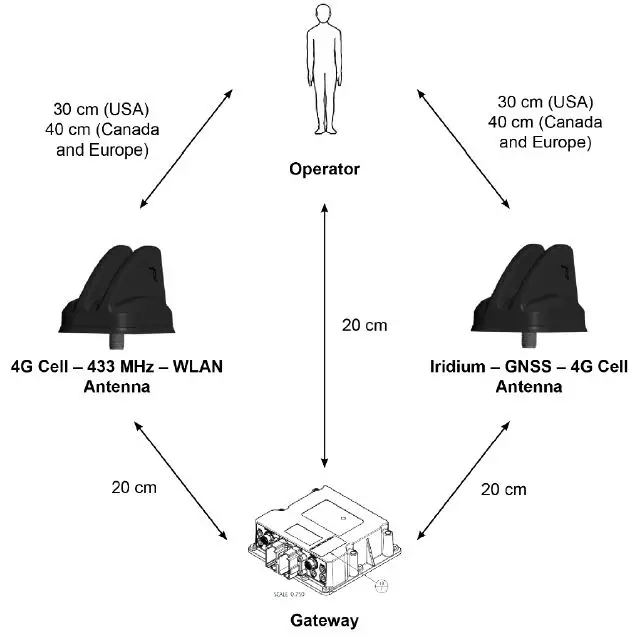
REGULATORY INFORMATION
FEDERAL COMMUNICATIONS COMMISSION NOTIFICATION TO USER
Models: 608065-000034, 608065-000040, 608065-000043, 240433
These devices comply with Part 15 of the Federal Communications Commission (FCC) Rules. Operation is subject to the following two conditions: (1) These devices may not cause harmful interference, and (2) these devices must accept any interference received, including interference that may cause undesired operation.
These devices must be operated as supplied by Appareo Systems LLC. Any changes or modifications made to these devices without the express written approval of Appareo Systems LLC may void the user’s authority to operate these devices.
This equipment has been tested and found to comply with the limits for a Class A digital device, pursuant to part 15 of the FCC Rules. These limits are designed to provide reasonable protection against harmful interference when the equipment is operated in a commercial environment. This equipment generates, uses, and can radiate radio frequency energy and, if not installed and used in accordance with the instruction manual, may cause harmful interference to radio communications. Operation of this equipment in a residential area is likely to cause harmful interference in which case the user will be required to correct the interference at his own expense.
INDUSTRY CANADA NOTIFICATIONS TO USER
Models: 608065-000034, 608065-000040, 608065-000043, 240433
These devices comply with Industry Canada license-exempt RSS standard(s). Operation is subject to the following two conditions: (1) this device may not cause interference, and (2) this device must accept any interference, including interference that may cause undesired operation of the device.
Under Industry Canada regulations, this radio transmitter may only operate using an antenna of a type and maximum (or lesser) gain approved for the transmitter by Industry Canada. To reduce potential radio interference to other users, the antenna type and its gain should be so chosen that the equivalent isotropically radiated power (e.i.r.p.) is not more than that necessary for successful communication.
SOUTH AFRICA-TYPE APPROVAL

UZBEKISTAN APPROVAL
This device has IEC Class 3 protection.
This document and the information contained herein are the property of Appareo Systems, LLC, and are confidential. They may not be disseminated or redistributed without the written permission of Appareo Systems, LLC.


