![]() EA00022 User Manual
EA00022 User Manual
Telematics Device EA00022
QSZTRACEA00022UM0101
Version: 1.01
International Telematics Solutions Innovator
www.queclink.com
| Document Title | EA00022 User Manual |
| Version | 1.01 |
| Date | 2021-09-07 |
| Status | Released |
| Document Control ID | QSZTRACEA00022UM0101 |
General Notes
Vehicle Control Module EA00022 integrates the components and functions such as OLED display, headlight control, Powertrain Control Module(PCM), Battery Module, brake actuator, throttle actuator, and speaker while providing communication with integrated Bluetooth and GPS positioning modules.
The EA00022 is designed to integrate within the scooter to provide communication to Bird Servers via LTE, provide local Bluetooth, and control vehicle behaviors such as remotely lock/unlock, track vehicle position, report status of the scooter. Additionally, by using the button on the panel, the user can perform numerous functions that will be region-specific and determined by Bird in deployment via firmware update. Selected information will be reported to the backend server to facilitate the basic functions of the scooter.
Copyright
This document contains proprietary technical information which is the property of Queclink. Copying of this document, distribution to others or using or communication of the contents thereof is forbidden without express authority. Offenders are liable to the payment of damages. All rights are reserved in the event of a patent grant or registration of a utility model or design. All specifications supplied herein are subject to change without notice at any time. Copyright © Queclink Wireless Solutions Co., Ltd. 2019
Revision History
| Version | Date | Author | Description of change |
| 1.00 | 2021-09-07 | Heymi Lin | Initial Version |
Introduction
The Vehicle Control Module EA00022 integrates the components and functions such as OLED display, headlight control, Powertrain Control Module (PCM), Battery Module, brake actuator, throttle actuator, and speaker while providing communication with integrated Bluetooth and GPS positioning modules.
The EA00022 is designed to integrate within the scooter to provide communication to Bird Servers via LTE, provide local Bluetooth and control vehicle behaviors such as remotely lock/unlock, track vehicle position, report status of the scooter. Additionally, by using the button on the panel, the user can perform numerous functions that will be region-specific and determined by Bird in deployment via firmware update. Selected information will be reported to the backend server to facilitate the basic functions of the scooter.
- EA00022 Series Products
Table 1. EA00022 ProductsModel No. Region Technology Operating Band (MHz) EA00022 US and Canada LTE-FDD/LTE-TDD/ UMTS/GSM LTE FDD: B2/B4/B5/B7/B12
B13/B25/B26
LTE TDD:B38/B41
UMTS: B2/B4/B5
GSM: 850MHz/1900MHz - Reference
Table 2. EA00022 Protocol ReferenceSN Document name Remark [1] EA00022 @Track Air Interface Protocol The air protocol interface between
EA00022 and backend server. - Terms and Abbreviations
Table 3. EA00022 Terms and AbbreviationsAbbreviation Description RXD Receive Data TXD Transmit Data OUT1 Output 1 OUT2 Output 2 IGN Ignition IN1 Input 1 GND Ground VIN External DC Power Input
Product Overview
- Product Appearance
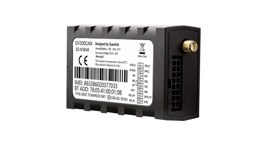
 Figure 1. EA00022 Appearance
 - Parts List
Table 4. EA00022 Series Parts ListName Picture Description EA00022 125.5mm*62.08mm*101.0mm tracker
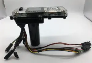 Figure 1. EA00022 Appearance
Interface Definition
The EA00022 harness has a 24-pin interface connector. It contains the connections for power, Speaker, headlight, and so on. The sequence and description of the connector are shown in the following figure: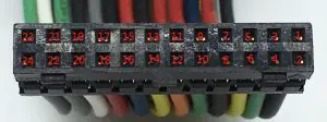 Figure 2. 24-pin Connector of the EA00022
Table 5. Description of 24-pin Connections
| Index | Description | Comment |
| 1 | GND | Power GND |
| 2 | 36V Perm | Power 12V |
| 3 | CAN_L | CAN_L |
| 4 | PWR_ENA | Power ENA |
| 5 | CAN_H | CAN_H |
| 6 | BR2_5V | BR2_Input |
| 7 | BR2_GND | BR2_GND |
| 8 | BR1_5V | BR1_Input |
| 9 | BR2_WP | BR2_Wake up |
| 10 | BR1_GND | BR1_GND |
| 11 | BR1_WP | BR1_Wake up |
| 12 | TR_5V | Throttle Input |
| 13 | TR_WP1 | Throttle Weak up1 |
| 14 | TR_GND | Throttle GND |
| 15 | TR_WP2 | Throttle Weak Up2 |
| 16 | USB_ID | USB ID |
| 17 | USB_VBS | USB_VBS |
| 18 | USB_GND | USB_GND |
| 19 | USB_D- | USB GND |
| 20 | USB_D+ | USB Input |
| 21 | SPK- | SPK GND |
| 22 | LED- | Headlight GND |
| 24 | SPK+ | SPK INPUT |
| 24 | LED+ | Headlight INPUT |
Device Cable Color
Table 6. EA00022 Device Cable Color Definition
| Definition | Color | Pin No. | Cable |
| GND | Black | 1 | 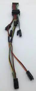 |
| 36V Perm | Red | 2 | |
| CAN_L | Green | 3 | |
| PWR_ENA | Blue | 4 | |
| CAN_H | Yellow | 5 | |
| BR2_5V | Red | 6 | |
| BR2_GND | Black | 7 | |
| BR1_5V | Red | 8 | |
| BR2_WP | Green | 9 | |
| BR1_GND | Black | 10 | |
| BR1_WP | Orange | 11 | |
| TR_5V | Red | 12 | |
| TR_WP1 | Yellow | 13 | |
| TR_GND | Black | 14 | |
| TR_WP2 | Blue | 15 | |
| USB_ID | Gray | 16 | |
| USB_VBS | Red | 17 | |
| USB_GND | Black | 18 | |
| USB_D- | White | 19 | |
| USB_D+ | Green | 20 | |
| SPK- | Gray | 21 | |
| LED- | White | 22 | |
| SPK+ | Gray | 23 | |
| LED+ | Green | 24 |
Started
- Opening and Closing the Casing
To open/close: Loosen or fasten the screws to open or to close. - Installing a SIM Card
Install the SIM card into the holder when power is off as shown below. Take care to align the cut mark, and then close the case. - Power Supply Connection
The red wire is a power line, the black wire is a ground line and the blue wire is the power EAN line. The input voltage range for this device is from 12V to 60V DC. Figure 5. Example of Connection for power
 - CAN Connection
The yellow wire is the CAN_H line, the green wire is the CAN_L line. Need to connect CAN-Bus tools communication. Figure 6. Example of Connection for CAN
 - Extra USB Connection
P4 Gray wire is USB ID line, the white wire is USB_D- line, The green wire is USB_D+ line, P5 red wire is a power line, the black wire is a ground line. P4 is for signal, P5 is for supply power.
- Throttle
The blue wire is throttled weak up 2 lines, the black wire is a ground line, the red wire is a power line, the yellow wire is throttle weak up 1 line. Figure 8. Example Connection to Throttle
 - Brake Right
The black wire is a ground line, the red wire is the power line, the orange wire is weak up line. Figure 9. Example connection to brake right
 - Brake Left
The black wire is a ground line, the red wire is the power line, the green wire is weak up line. Figure 10. Example connection to brake left
 - Headlight
The white wire is a ground line, the green wire is the power line. Figure 11. Example connection to the headlight
 - Speaker
The white wire is a ground line, the green wire is a power line
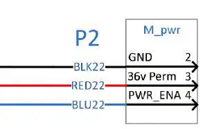 Figure 5. Example of Connection for power
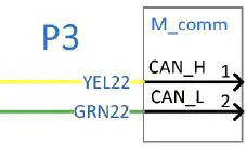 Figure 6. Example of Connection for CAN
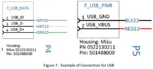
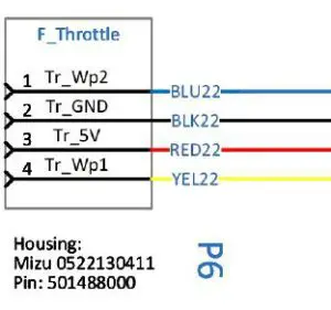 Figure 8. Example Connection to Throttle
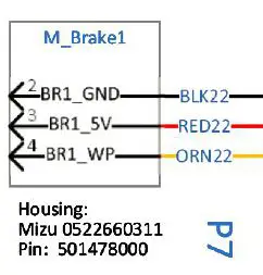 Figure 9. Example connection to brake right
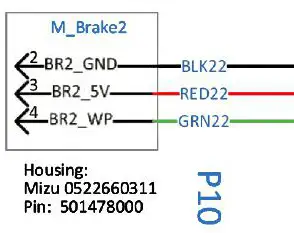 Figure 10. Example connection to brake left
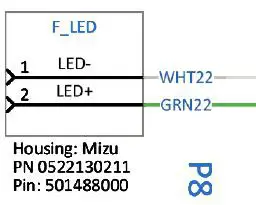 Figure 11. Example connection to the headlight
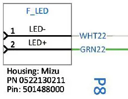 Figure 12. Example connection to the speaker
Basic communication
EA00022 Can communicate with the backend server through LTE Cat-M network, and transfer reports of emergency, Geo-fencing, device status and schedule GPS to position, the etc…service provider is easy to setup their tracking platform based on the functional wireless.
BLE
- BLE working mode explanation
EA00022 is installed in the shared scooter and supplied by the main battery of the scooter. With the external power(main battery of scooter) supplying, the BLE of EA00022 works. Otherwise, with the backup battery of EA00022 supplying, BLE stops working. - BLE instructions
Heartbeat packet uploaded from EA00022 to Server includes 20 bytes dynamic password (BLE command password). After successfully connecting with the BLE of EA00022, It is able to send command <AT+BKSCT=BLE Command Password,0$> to unlock Scooter or <AT+BKSCT=BLE Command Password,1$>to lock Scooter by BLE channel.
NFC
- NFC working mode explanation
EA00022 is installed in the shared scooter and supplied by the main battery of the scooter. With the external power(main battery of scooter) supplying, the NFC of EA00022 works. Otherwise, with the backup battery of EA00022 supplying, NFC stops working.
FCC Certification
Any changes or modifications not expressly approved by the party responsible for compliance could void the user’s authority to operate the equipment.
This device complies with part 15 of the FCC Rules. Operation is subject to the following two conditions: (1) This device may not cause harmful interference, and(2) This device must accept any interference received, including interference that may cause undesired operation.
FCC Radiation Exposure Statement:
This equipment complies with FCC radiation exposure limits set forth for an uncontrolled environment. This equipment should be installed and operated with a minimum distance of 20cm between the radiator& your body.
IMPORTANT NOTE:
Note: This equipment has been tested and found to comply with the limits for a Class B digital device, pursuant to part 15 of the FCC Rules. These limits are designed to provide reasonable protection against harmful interference in a residential installation. This equipment generates, uses, and can radiate radio frequency energy and, if not installed and used in accordance with the instructions, may cause harmful interference to radio communications. However, there is no guarantee that interference will not occur in a particular installation. If this equipment does cause harmful interference to radio or television reception, which can be determined by turning the equipment off and on, the user is encouraged to try to correct the interference by one or more of the following measures:
- Reorient or relocate the receiving antenna.
- Increase the separation between the equipment and receiver.
- Connect the equipment into an outlet on a circuit different from that to which the receiver is connected.
- Consult the dealer or an experienced radio/TV technician for help.
ISED RSS Warning/ISED RF Exposure Statement
ISED RSS Warning: This device complies with Innovation, Science, and Economic Development Canada licence‐exempt RSS standard(s). Operation is subject to the following two conditions: (1) this device may not cause interference, and (2) this device must accept any interference, including interference that may cause undesired operation of the device.
ISED RF exposure statement:
This equipment complies with ISED radiation exposure limits set forth for an uncontrolled environment. This equipment should be installed and operated with a minimum distance of 20cm between the radiator& your body. This transmitter must not be co‐ ocated or operating in conjunction with any other antenna or transmitter.


