Panasonic FV-SW20VEC1 LCD Wired Wall Control Panel
READ AND SAVE THESE INSTRUCTIONS
Thank you for purchasing this Panasonic product.
Please read these instructions carefully before attempting to install, operate or service the Panasonic product. Please carefully read the “GENERAL SAFETY INFORMATION” (P.2~3) of this manual before use. Failure to comply with instructions could result in personal injury or property damage. Please explain to users how to operate and maintain the product after installation, and this booklet should be presented to users. Please retain this booklet for future reference.
GENERAL SAFETY INFORMATION
For Your Safety
To reduce the risk of injury, loss of life, electric shock, fire, malfunction, and damage to equipment or property, always observe the following safety precautions.
Explanation of symbol word panels
The following symbol word panels are used to classify and describe the level of hazard, injury, and property damage caused when the denotation is disregarded and improper use is performed.
 Denotes a potential hazard that could result in death or serious injury.
 Denotes a hazard that could result in minor injury .
 Denotes a hazard that could result in property damage.
The following symbols are used to classify and describe the type of instructions to be observed
![]() This symbol is used to alert users to a specific operating procedure that must not be performed.
This symbol is used to alert users to a specific operating procedure that must not be performed.![]() This symbol is used to alert users to a specific operating procedure that must be followed in order to operate the unit safely.
This symbol is used to alert users to a specific operating procedure that must be followed in order to operate the unit safely.![]() Th is symbol is used to alert users not to disassemble the equipment.
Th is symbol is used to alert users not to disassemble the equipment.
![]() Do not install using methods not approved in the instructions.
Do not install using methods not approved in the instructions.![]() Installation must be performed by qualified person(s) in accordance with all applicable codes and standards, including fire-rated construction. Otherwise, a fire may be caused.
Installation must be performed by qualified person(s) in accordance with all applicable codes and standards, including fire-rated construction. Otherwise, a fire may be caused.![]() Disconnect power source before working on the product.
Disconnect power source before working on the product.![]() Do not disassemble the unit. It may cause fire or electric shock.
Do not disassemble the unit. It may cause fire or electric shock.![]() Never install the unit in a high humidity space.
Never install the unit in a high humidity space.![]() Do not spray flammable cleaner directly onto the controller.
Do not spray flammable cleaner directly onto the controller.![]() Do not touch the controller with wet hands or pour water on the controller, it may cause fire or electric shock.
Do not touch the controller with wet hands or pour water on the controller, it may cause fire or electric shock.![]() Do not install in a place where flammable gas may leak.
Do not install in a place where flammable gas may leak.![]() Discontinue use immediately if abnormal operation occurs.
Discontinue use immediately if abnormal operation occurs.![]() Do not use the unit for any purpose other than is what is intended.
Do not use the unit for any purpose other than is what is intended.
![]() Please wear appropriate personal protective equipment .
Please wear appropriate personal protective equipment .![]() Where appropriate, use the special-purpose or dedicated parts, such as the provided mounting fixtures, otherwise personal injury may result.
Where appropriate, use the special-purpose or dedicated parts, such as the provided mounting fixtures, otherwise personal injury may result.![]() Inspect all wiring connections ensuring they meet the correct current capacity.
Inspect all wiring connections ensuring they meet the correct current capacity.![]() Disconnect power by switching off wall control first, then main switch and unplug the power plug before working on unit.
Disconnect power by switching off wall control first, then main switch and unplug the power plug before working on unit.
![]() Don’t press the wall control screen. It may cause a fault code, electric shock and screen breakage.
Don’t press the wall control screen. It may cause a fault code, electric shock and screen breakage.![]() Select a location where the device can be easily installed and accessed.
Select a location where the device can be easily installed and accessed.![]() Select a location where the device will stay dry and not directly exposed to sunshine .
Select a location where the device will stay dry and not directly exposed to sunshine .![]() Select a flat location to prevent distortion. (Distortion may damage the wall control or cause a fault code.)
Select a flat location to prevent distortion. (Distortion may damage the wall control or cause a fault code.)![]() If installation position is excessive high or low, it may be difficult to view the display screen, it’s important to select the position where it can be easily viewed andaccessed. (Standard height is about 5 ft (1.5m) from the ground)
If installation position is excessive high or low, it may be difficult to view the display screen, it’s important to select the position where it can be easily viewed andaccessed. (Standard height is about 5 ft (1.5m) from the ground)![]() As shown in the figure, please secure the enough space around the installation position. Fix the base of wall control on the wall.
As shown in the figure, please secure the enough space around the installation position. Fix the base of wall control on the wall.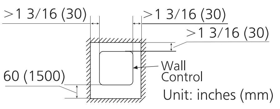
SUPPLIED ACCESSORIES
Part name | Appearance | Quantity |
| Wall control | 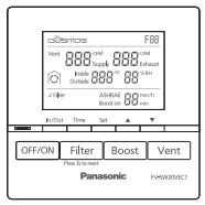 | 1 |
| Screws (ST4X25) |  | 2 |
| Installation and operating instructions |  | 1 |
| Wall anchors |  | 2 |
| Limited warranty |  | 1 |
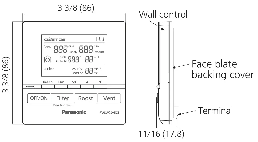
DIMENSIONS
Unit: inches (mm)
INSTALLATION
- Wiring preparation

 It’s recommended to use the cable (14AWG~26AWG) for connecting product and V wall control, and the length should not be longer than 33.3 ft (10 m).
Note
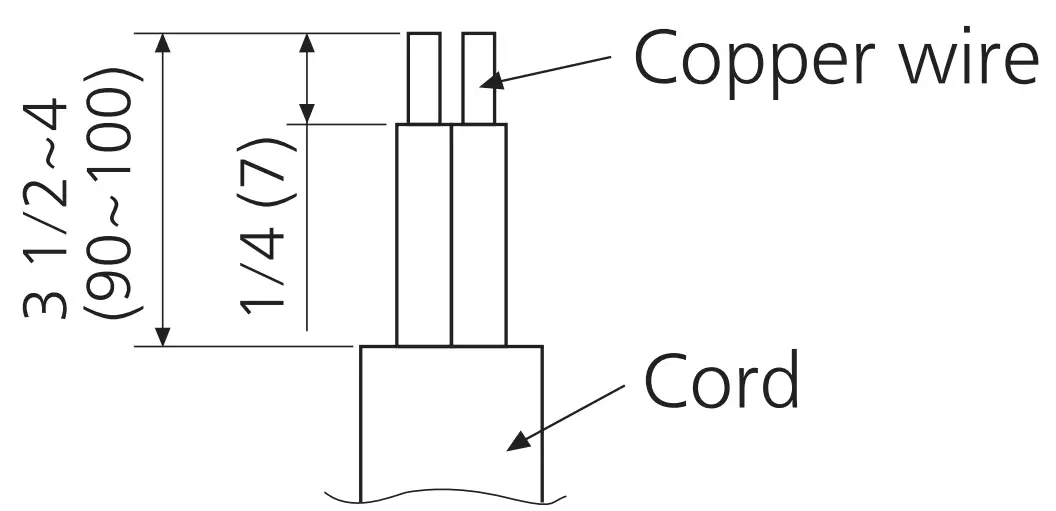
Strip insulation cover for each wires as shown below. Unit: inches (mm)
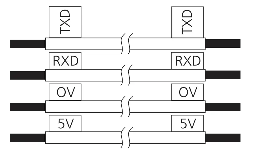
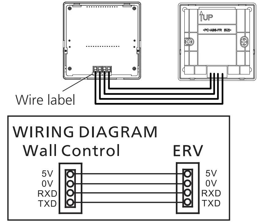
■ Attach matching wire-labels to each side of cable.
- Installing the wall control
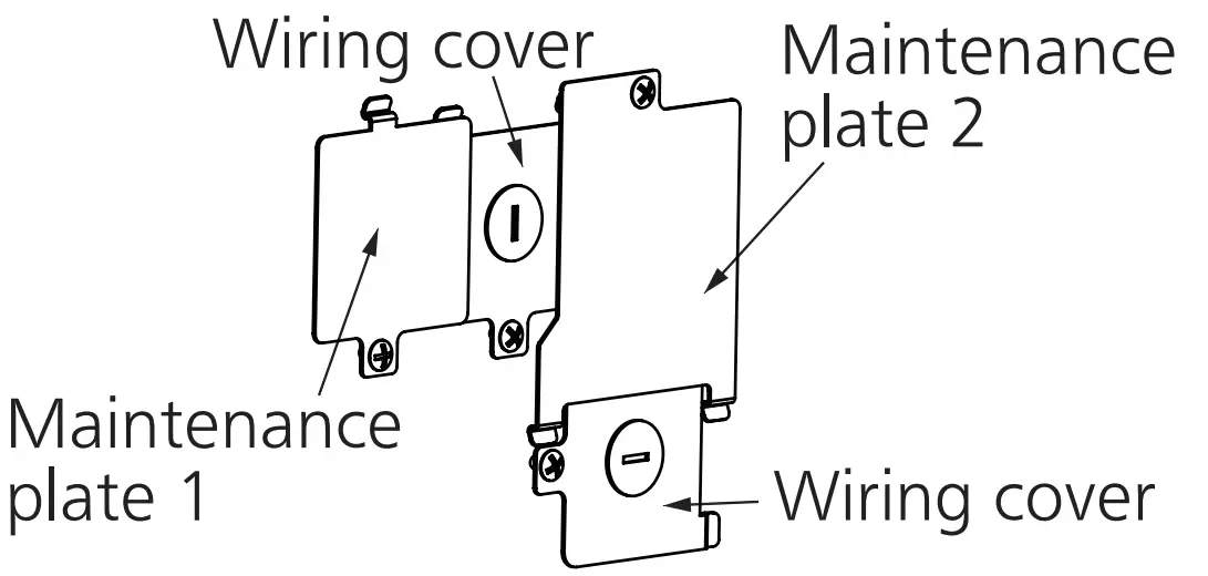
(1) Open the knock-out hole and remove maintenance plate 1 and 2 and wiring cover.
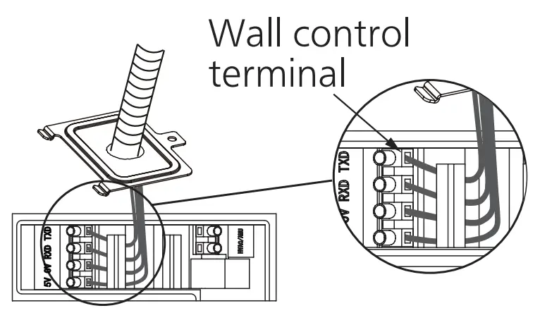
(2) Thread cables through conduits respectively and install the conduits into knock-out holes.
(3) Insert cables into the corresponding terminals of product. Make sure the lead wire labels correspond to the terminal label and the screw of terminal securely fastens the copper wire and no copper wire is exposed.
(4) Re-install the wiring covers and maintenance plates.
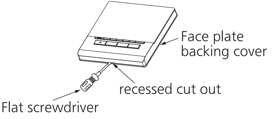
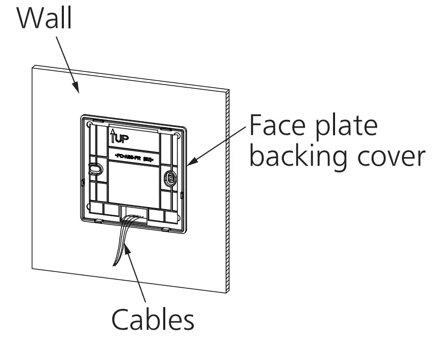
(5) Remove the face plate backing cover from the backing plate with a small flat screwdriver.
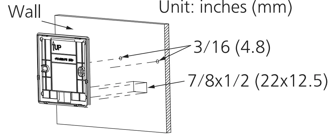
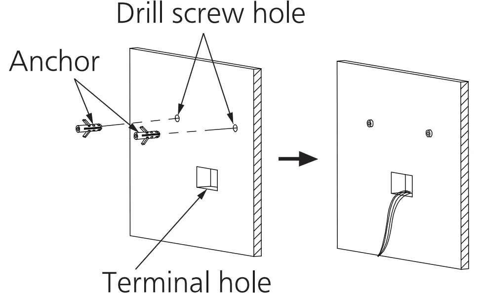
(6) Temporarily put the face plate backing cover on the wall, mark terminal hole and screw positions.
(7) Remove the face plate backing cover, cut the terminal hole and drill screw holes (Ø5/32 ft (Ø4 mm)).
(8) Insert wall anchors, and fix the face plate backing cover on the wall with two screws.
(9) Route the cables form the unit tothe terminal hole.
(10) Insert cables into the corresponding terminals of wall control according to the lead wire labels.
(11) Fix the wall control screen to the face plate backing cover.
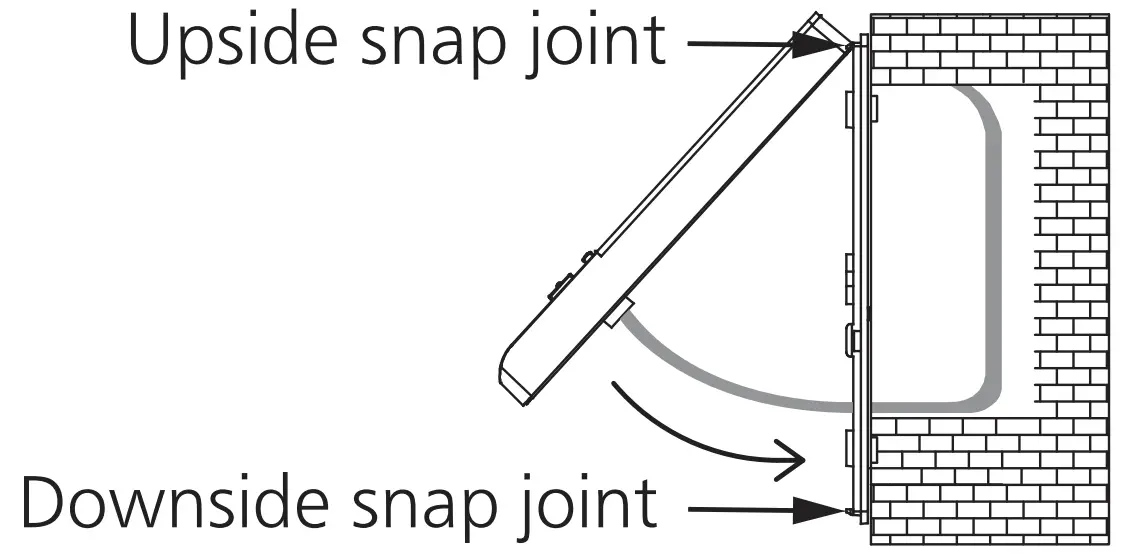
![]() Make sure cables are not caught by circuit-board or resin clip. Otherwise, it may cause electrical leakage.
Make sure cables are not caught by circuit-board or resin clip. Otherwise, it may cause electrical leakage.![]() Don’t press the screen, it may cause V distortion or break altogether.
Don’t press the screen, it may cause V distortion or break altogether.
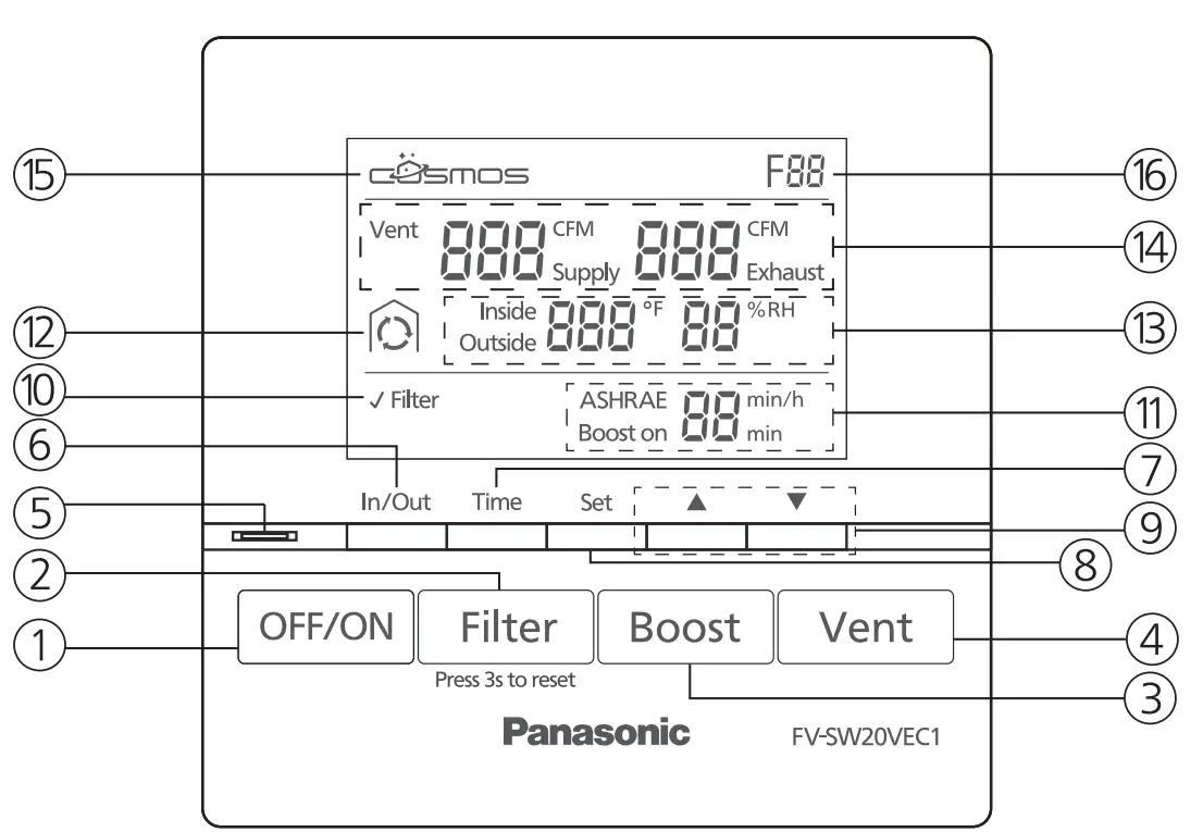
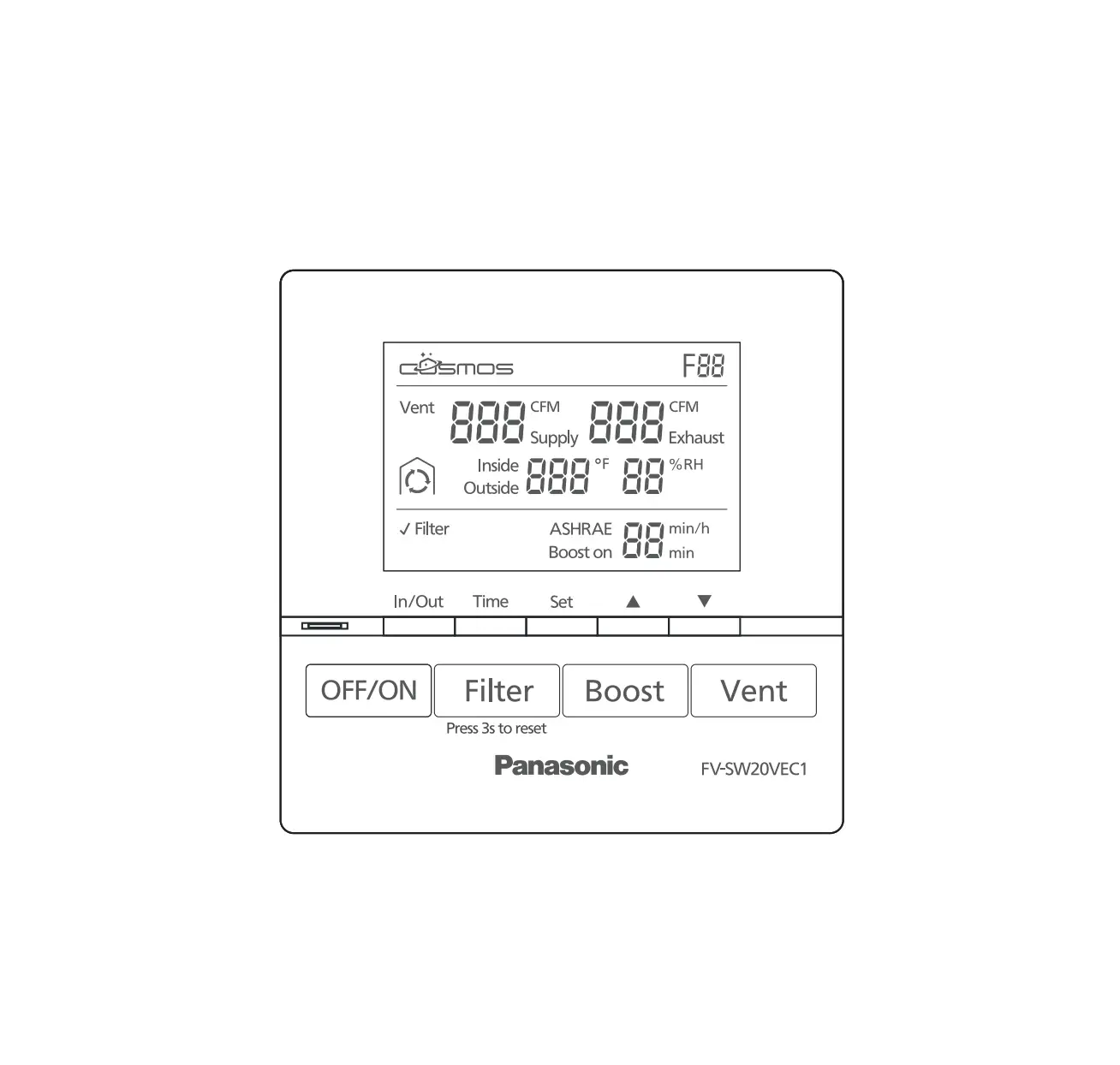
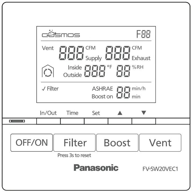
① OFF/ON Button
Product standby/ running
② Filter Reset Button
Press the button after maintenance for resetting accumulated running time
③Boost Button
Activate / Deactivate Boost Mode
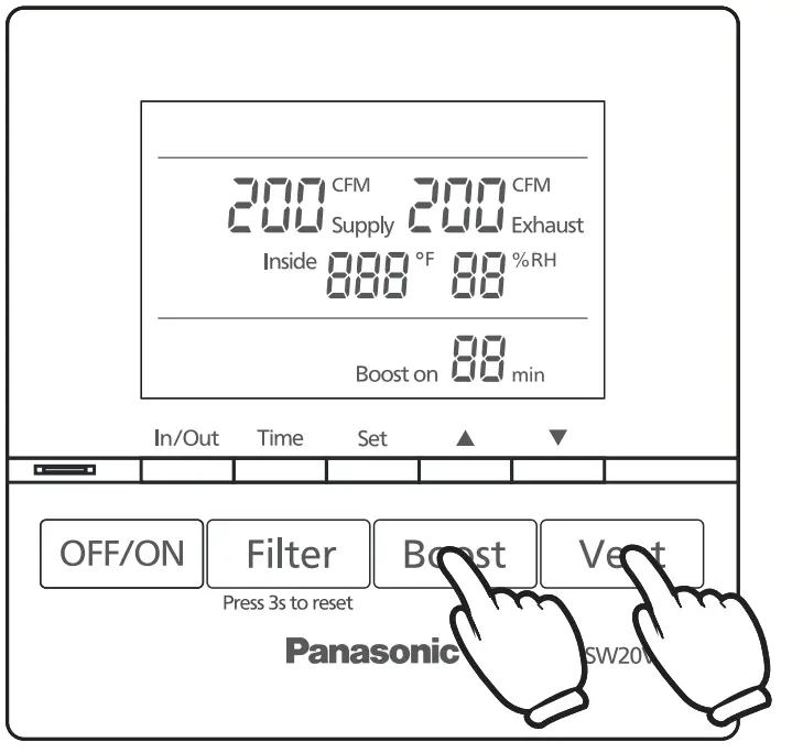
④ Vent Button
Set supply air volume / exhaust air volum
⑤ Boost display Light
Green: Boost mode on
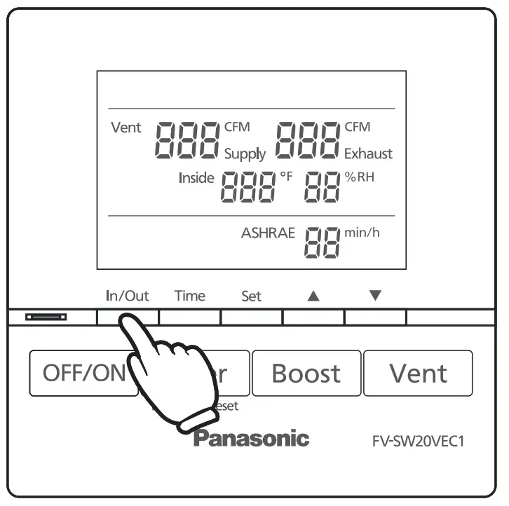
⑥ In/Out Button
Display the inside or outside temperature and humidity
⑦ Time Button
- Set Boost time
- Set ASHRAE time
⑧ Set Button
Confirm the air volume / time setting
⑨ ▲▼Button
- Set the air volume setting
- Set time “min, min/h”
⑩ Filter Maintenance Display
Display filter needs to be cleaned or changed
⑪ ASHRAE/Boost on time Display
- Display ASHRAE time
- Display Boost time
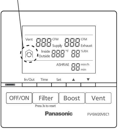
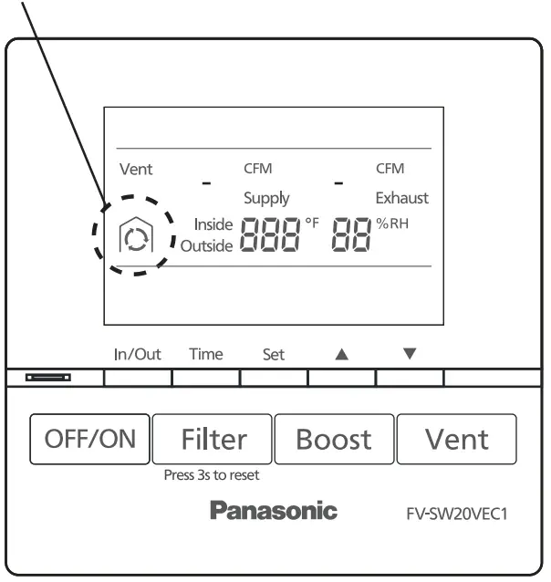
⑫ Display Defrost Mode
Display the product in low temperature protection mode
- Air exchange:

- Circulation:

- Stop operating:

⑬ Display inside & outside temperature and humidity
- Display inside temperature and humidity
- Display outside temperature and humidity
⑭ Air volume Display
Display supply air volume and exhaust air volume
⑮ COSMOS Display
Display when Cosmos module is connected
⑯ Error Code Display
An error code is displayed when the product is in failure, check troubleshooting guide for reference
OPERATION
Standby mode
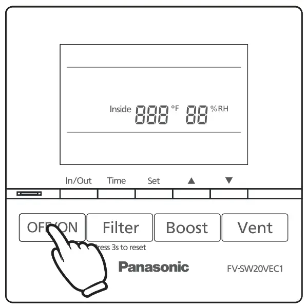
- Press”
 “, the unit starts/standby
 - The inside temperature (°F) and humidity(%) display in standby mode
- The unit operates in the last mode before stopping
Note
When connected to the wall control, the control panel of the FV-20VEC1 will be disabled.
When the wall control is disconnected from the ERV, the ERV controls will be
Function mode
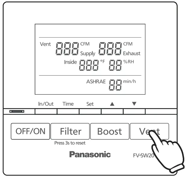
- Air volume setting (Default: 120 CFM)

① Press” ” to switch between supply air volume and exhaust air volume.
② Press “
 ” to choose and press”▲▼” to adjust the volume (60, 80, 100, 120, 140, 160, 180, 200).
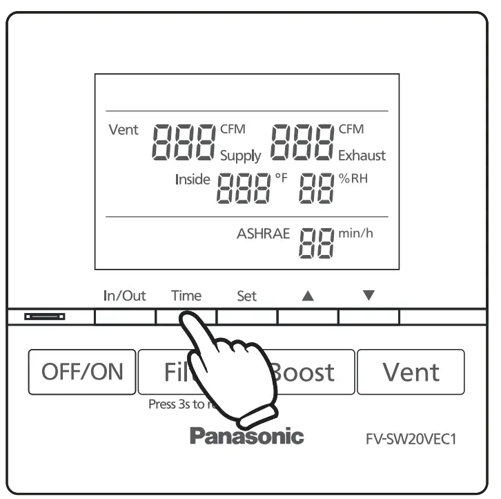
③ Press “” again to confirm the setting. - ASHRAE time setting (Default: 60 min/h)
① Press the “ ” to change the ASH RAE time.
② Press “” to choose and press “▲▼” to adjust the ASH RAE time (60, 50, 40, 30, 20, 10).
③ Press “” again to confirm the setting.Note
For more detailed information regarding the ASHRAE intermittent timer control, please refer to the FV-20VEC1 manual. - Press “” to switch temperature and humidity between inside and outside.

 ” to choose and press”▲▼” to adjust the volume (60, 80, 100, 120, 140, 160, 180, 200).
 ” to change the ASH RAE time.
 ” to switch temperature and humidity between inside and outside.
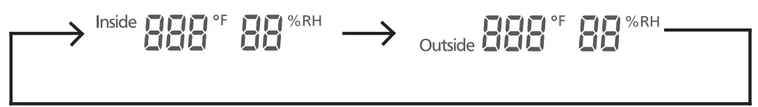
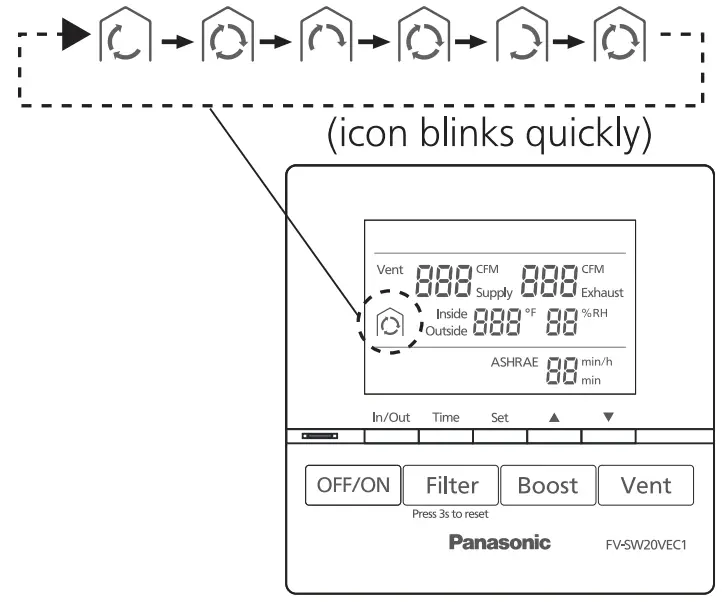
Defrost mode
- When outdoor temperature<14 °F, ERV will enter defrost mode, defrost icon will be displayed as below.
① Heat exchange:
Defrost icon display
② Circulation:
③ Stop operating:
Defrost icon display
Note
About defrost mode.
- The max ventilation air volume setting is 180 CFM in defrost mode.
- When ventilation air volume is 60 CFM~120 CFM, circulation air volume is 180 CFM. When ventilation air volume is 130 CFM ~ 180 CFM, circulation air volume is 230 CFM.
- For more detailed information regarding the defrost mode, please refer to the FV-20VEC1 manual.
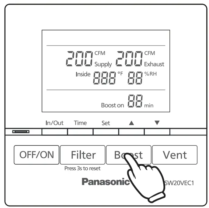
Boost mode
- Press “” to enter boost mode, supply and exhaust air volume constant to 200 CFM.
- Boost on _time setting (Default: 20 min) Time

① Press “” to change the boost on time, and press “▲▼” to adjust (60, 50, 40, 30, 20, 10)
② Press “” to confirm the setting - Exit boost mode:

① Timer finishes.
② Press “” again.
③ Press “” to set supply and exhaust air volume, then ERV will exit boost mode.
Note
For more information on filter maintenance, please refer to the FV-20VEC1 maintenance label on the front panel.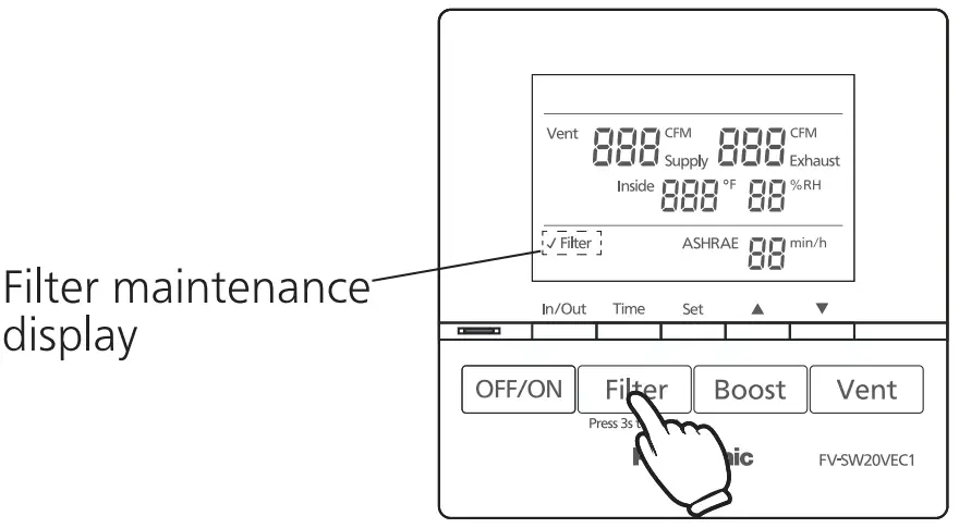
TROUBLESHOOTING
- If product is malfunctioning, a fault code will display. Please reference the following codes below.
| Fault code | Problem | Action |
| F01 | Wall control communication error | Please disconnect the power and contact the dealer to check the wall control wiring connect |
| F02 | Cosmos communication error | Please disconnect the power and contact the dealer for repair |
| F03 | PCB board error | Please disconnect the power and contact the dealer for repair |
| F10 | OA temperature sensor error | Please disconnect the power and contact the dealer for repair |
| F11 | OA humidity sensor error | Please disconnect the power and contact the dealer for repair |
| F12 / F13 | RA temperature and humidity sensor error | Please disconnect the power and contact the dealer for repair |
| F20 | SA motor error | Please disconnect the power and contact the dealer for repair |
| F21 | EA motor error | Please disconnect the power and contact the dealer for repair |
| F30 | OA damper error | Please disconnect the power and contact the dealer for repair |
| F31 | EA damper error | Please disconnect the power and contact the dealer for repair |
| F32 | Center damper error | Please disconnect the power and contact the dealer for repair |
SPECIFICATIONS
| Model No. | Voltage | Frequency (Hz) | Power consumption (W) | Net weight lb.(kg) |
| FV-SW20VEC1 | DC 5 V | – | 0.44 | 0.187 (0.085) |
PRODUCT SERVICE
Warning Concerning Removal of Covers.
The unit should be serviced by qualified technicians only.
Your product is designed and manufactured to ensure a minimum of maintenance.
Should your unit require service or parts, call Panasonic Call Center at 1-866-292-7299 (USA) or 1-800-669-5165 (Canada).
Panasonic Corporation of North America
Two Riverfront. Plaza, Newark, NJ 07102
www.panasonic.com
Panasonic Canada Inc.
5770 Ambler Drive, Mississauga, Ontario L4W 2T3
www.panasonic.com
© Panasonic Corporation 2021