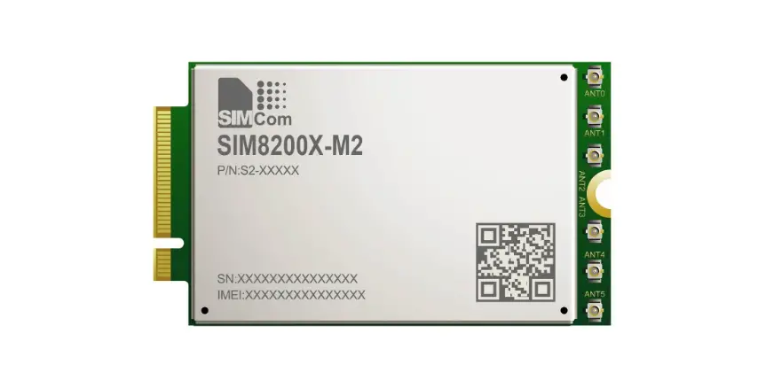
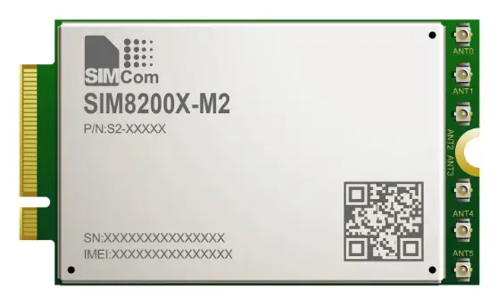
 TRITOM SG500M2-X 5G M.2 Module
- FCC-ID: 2ACARSG500M2
- Module name: SG500M2-X
- Date:October 21, 2020

Copyright
Copyright © 2019 TRICASCADE, INC. All rights reserved.
Without the prior written permission of the copyright holder, any company or individual is prohibited to excerpt, copy any part of or the entire document, or distribute the document in any form.
Notice
The document is subject to update from time to time owing to the product version upgrade or other reasons. Unless otherwise specified, the document only serves as the user guide. All the statements, information and
suggestions contained in the document do not constitute any explicit or implicit guarantee.
Foreword
Introduction
This document describes the hardware of the TRICASCADE® SG500M2-X 5G M.2 Module products. It helps you quickly retrieve interface specifications, electrical and mechanical details, and information on the requirements to be considered for integrating further components.
Safety Information
The following safety precautions must be observed during all phases of operation, such as usage, service or repair of any cellular terminal or mobile incorporating with SG500M2-X 5G M.2 Module. Manufacturers of the cellular terminal should send the following safety information to users and operating personnel, and incorporate these guidelines into all manuals supplied with the product. If not so, TRICASCADE assumes no liability for customers’ failure to comply with these precautions.
Full attention must be given to driving at all times in order to reduce the risk of an accident. Using a mobile while driving (even with a hands free kit) causes distraction and can lead to an accident. Please comply with laws and regulations restricting the use of wireless devices while driving.
Switch off the cellular terminal or mobile before boarding an aircraft. The operation of wireless appliances in an aircraft is forbidden to prevent interference with communication systems. If the device offers an Airplane Mode, then it should be enabled prior to boarding an aircraft.Please consult the airline staff for more restrictions on the use of wireless devices on boarding the aircraft.
Wireless devices may cause interference on sensitive medical equipment, so please be aware of the restrictions on the use of wireless devices when in hospitals, clinics or other healthcare facilities.
Cellular terminals or mobiles operating over radio signals and cellular network cannot be guaranteed to connect in all possible conditions (for example, with unpaid bills or with an invalid (U) SIM card). When emergent help is needed in such conditions, please remember using emergency call. In order to make or receive a call, the cellular terminal or mobile must be switched on in a service area with adequate cellular signal strength.
The cellular terminal or mobile contains a transmitter and receiver. When it is ON, it receives and transmits radio frequency signals. RF interference can occur if it is used close to TV set, radio, computer or other electric equipment.
In locations with potentially explosive atmospheres, obey all posted signs to turn off wireless devices such as your phone or other cellular terminals. Areas with potentially explosive atmospheres include fueling areas, below decks on boats, fuel or chemical transfer or storage facilities, areas where the air contains chemicals or particles such as grain, dust or metal powders, etc.
Overview
Introduction
SG500M2-X 5G M.2 Module is a highly integrated 5G NR wireless communication module that adopts standard PCIe SG500M2-X 5G M.2 interface and backward supports with LTE/WCDMA system. It is applicable to most broadband communication networks of the mobile operator across the world.
SG500M2-X has capability on 5G NR Sub6 and mmWave on HW design and using SW to inactive on 5G NR mmWave function.
Specification
Table 2-1 SG500M2-X 5G M.2 Module features
| Specification | ||
| Platform | QCT SDX55 Cortex-A7 up to 1.5 GHz | |
| Memory | 4Gb NAND Flash (ONFI) with 4Gb LPDDR4X(1.8GHz) MCP | |
| Operating Band | 5G NR_ Sub6 : n2, n5, n41, n66, n71 | |
| 5G NR_mmWave: n258, n260, n261 (Using SW to inactive 5G mmWave fuction) | ||
| LTE FDD: B2, B4, B5, B7, B12, B13, B14, B25, B26, B30, B66, B71 LTE FCC Downlink only: B29 | ||
| LTE TDD: B41, B48 LTE TDD Downlink only: B46 | ||
| WCDMA/HSPA+: B1, B2, B4, B5, B8 | ||
| Simultaneous GPS L1, GLONASS(GLO), Galileo(GAL) and BeiDou(BDS) | ||
| Network option | SA | Option 2 |
| NSA | Option 3x/3a | |
| Downlink | LTE | LTE CAT20 |
| 5G sub-6 | 1CC; Max BW 100MHz; MIMO 4×4 | |
| 5G mmWave | 8CC; Max BW 800MHz;MIMO 2×2 | |
| Uplink | LTE | LTE CAT13 |
| 5G sub-6 | 1CC; Max BW 100MHz; | |
| 5G mmWave | 8CC; Max BW 800MHz;MIMO 2×2 | |
| HPUE ( Class 2) | B41 | |
| DL 4×4 MIMO | B2, B4, B7, B25, B30, B41, B48, B66 n2, n41, n66 | |
| Carrier aggregation | ULCA, DLCA and EN-DC | |
| SRS antenna switching | n41 : 1T2R(NSA) | |
| Power Supply | DC 3.135V~3.465V, Typical 3.3V | |
| Temperature | Operating temperature[1]:-10°C ~+55°C | |
| Extended temperature[2] : -25°C ~+75°C | ||
| Storage temperature: -40°C ~+85°C | ||
| Physical characteristics | Interface: PCIe M.2 Key B | |
| Dimension: 30×52 mm, Thickness=2.25 mm(typ.) | ||
| Weight: 9.3g | ||
| Interface | ||
|
Antenna Connector | 3/4G/Sun6G Antenna x 4 | |
| mmWave Antenna x 3 | ||
| Support 4×4 MIMO | ||
|
Function Interface | Single USIM 2.95V/1.8V | |
| PCIe Gen3_1xlane | ||
| USB2.0 HS /USB3.1 SS | ||
| W_Disable# | ||
| Body Sar | ||
| LED control pin | ||
| Tunable antenna(1xMIPI) | ||
| I2S(Reserved) | ||
| Software | ||
| Driver | Windows 19H1 and later, Linux kernel v4.4 [3] | |
| Protocol Stack | IPV4/IPV6 | |
| AT commands | 3GPP TS 27.007 and 27.005 | |
| Firmware update | FOTA |
| Others feature | Windows MBIM support |
| Windows update | |
| Support 5G NR NSA | |
| Multiple carrier aggregation | |
| AGNSS |
Operating Band
The SG500M2-X 5G M.2 Module operating bands of the antennas are as follows:
Table 4-5
| Band name | Tx (MHz) | Rx (MHz) | LTE | UMTS | 5G NR |
| PCS (1900) | 1850 – 1910 | 1930 – 1990 | B2 | B2 | n2 |
| AWS | 1710 – 1755 | 2110 – 2155 | B4 | B4 | – |
| Cell (850) | 824 – 849 | 869 – 894 | B5 | B5 | n5 |
| IMT-E (2600) | 2500 – 2570 | 2620 – 2690 | B7 | ||
| 700 lower A–C | 699 – 716 | 729 – 746 | B12 | ||
| 700 upper C | 777 – 787 | 746 – 756 | B13 | ||
| 700 D | 788 – 798 | 758 – 768 | B14 | ||
| PCS + G | 1850 – 1915 | 1930 – 1995 | B25 | ||
| B26 | 814 – 849 | 859 – 894 | B26 | ||
| FLO | N/A | 716 – 728 | B29 | ||
| WCS | 2305 – 2315 | 2350 – 2360 | B30 | ||
| B41/B41-XGP | 2496 – 2690 | B41 | n41 | ||
| B46 | 5150 – 5925 | B46 | |||
| B48 | 3550 – 3700 | B48 | |||
| B66 | 1710 – 1780 | 2110 – 2200 | B66 | n66 | |
| B71 | 663 – 698 | 617 – 652 | B71 | n71 | |
Transmitting Power
The transmitting power for each band of the SG500M2-X XX Module as shown in the following table:
Table 4-6 WCDMA
| Mode | Band | Typical Value (dBm) | Note |
|
WCDMA | Band 1 | 23.5 | ±2 |
| Band 2 | 23.5 | ±2 | |
| Band 4 | 23.5 | ±2 | |
| Band 5 | 23.5 | ±2 | |
| Band 8 | 23.5 | ±2 |
Table 4-7 LTE FDD
| Mode | Band | Typical Value (dBm) | Note |
|
LTE FDD | Band 2 | 23 | ±2 |
| Band 4 | 23 | ±2 | |
| Band 5 | 23 | ±2 | |
| Band 7 | 23 | ±2 | |
| Band 12 | 23 | ±2 | |
| Band 13 | 23 | ±2 | |
| Band 14 | 23 | ±2 | |
| Band 25 | 23 | ±2 | |
| Band 26 | 23 | ±2 | |
| Band 30 | 23 | ±2 | |
| Band 66 | 23 | ±2 | |
| Band 71 | 23 | ±2 |
Table 4-8 LTE TDD
| Mode | Band | Typical Value (dBm) | Note |
| LTE TDD | Band 41 | 26 | ±2 |
| Band 48 | 23 | ±2 |
Table 4-9 NR-FR1 FDD
| Mode | Band | Typical Value (dBm) | Note |
|
NR-FR1 FDD | n2 | 23 | ±2 |
| n5 | 23 | ±2 | |
| n66 | 23 | ±2 | |
| n71 | 23 | ±2 |
Table 4-10 NR-FR1 TDD
| Mode | Band | Typical Value (dBm) | Note |
| NR-FR1 TDD | n41 | 23 (LTE+NR) | ±2 |
Antennas (Maximum allowable gain
| Vendor | Modulation | Frequency (MHz) | Max. Allowable Antenna Gain (dBi) |
|
Pulse | WCDMA / HSPA Band II | 1852.4 ~ 1907.6 | 10.07 |
| WCDMA / HSPA Band IV | 1712.4 ~ 1752.6 | 6.20 | |
| WCDMA / HSPA Band V | 826.4 ~ 846.6 | 9.42 | |
| LTE Band 2 / NR n2 | 1850 ~ 1910 | 7.50 | |
| LTE Band 4 | 1710 ~ 1755 | 6.14 | |
| LTE Band 5 / NR n5 | 824 ~ 849 | 7.00 | |
| LTE Band 7 | 2500 ~ 2570 | 8.00 | |
| LTE Band 12 | 699 ~ 716 | 6.40 | |
| LTE Band 13 | 777 ~ 787 | 7.00 | |
| LTE Band 14 | 788 ~ 798 | 9.21 | |
| LTE Band 25 | 1850 ~ 1915 | 8.39 | |
| LTE Band 26 | 824 ~ 849 | 7.40 | |
| LTE Band 26 (Part 90S) | 814 ~ 824 | 7.40 | |
| LTE Band 30 | 2305 ~ 2315 | 1.22 | |
| LTE Band 41 / NR n41 | 2496 ~ 2690 | 7.68 | |
| LTE Band 48 | 3550 ~ 3700 | -1.92 | |
| LTE Band 66 / NR n66 | 1710 ~ 1780 | 7.50 | |
| LTE Band 71 / NR n71 | 663 ~ 698 | 6.50 |
Legal Information
FCC Statement:
Any device incorporating this module must include an external, visible, permanent marking or label which states: “Contains FCC ID: 2ACARSG500M2”
The SG500M2-X modular transmitter is only FCC authorized for the specific rule parts (i.e., FCC transmitter rules) listed on the grant, and that the host product manufacturer is responsible for compliance to any other FCC rules that apply to the host not covered by the modular transmitter grant of certification.
The final host product still requires Part 15 Subpart B compliance testing with the modular transmitter installed.
15.21
You are cautioned that changes or modifications not expressly approved by the part responsible for compliance could void the user’s authority to operate the equipment.
This device complies with Part 15 of the FCC Rules. Operation is subject to the following two conditions:
- this device may not cause harmful interference and
- this device must accept any interference received, including interference that may cause undesired operation of the device.
This module has been tested and found to comply with the following requirements for Modular Approval.
- Part 2.1046 – Measurements required: RF power output
- Part 22H – Cellular radiotelephone service
- Part 24E – Broadband PCS
- Part 27C – Technical standards
- Part 90S – Regulations governing licensing and use of frequencies in the 806-824, 851-869, 896-901, and 935-940 MHz Bands, 851-869, 896-901, and 935-940 MHz Bands
- PART 96—CITIZENS BROADBAND RADIO SERVICE
FCC RF Exposure:
This equipment complies with FCC RF radiation exposure limits set forth for an uncontrolled environment. This equipment should be installed and operated with a minimum distance of 20 centimeters between the radiator and your body.


