LANTRONIX M110 Series Cellular Modem
Intellectual Property
© 2022 Lantronix, Inc. All rights reserved. No part of the contents of this publication may be transmitted or reproduced in any form or by any means without the written permission of Lantronix.
Lantronix is a registered trademark of Lantronix, Inc. in the United States and other countries.
Patented: www.lantronix.com/legal/patents/. Additional patents pending.
Windows and Internet Explorer are registered trademarks of Microsoft Corporation. Firefox is a registered trademark of the Mozilla Foundation. Chrome is a trademark of Google Inc. All other trademarks and trade names are the property of their respective holders.
Warranty
For details on the Lantronix warranty policy, please go to our web site at
www.lantronix.com/support/warranty/
Contacts
Lantronix, Inc.
48 Discovery, Suite 250
Irvine, CA 92618, USA
Toll Free: 800-526-8766
Phone: 949-453-3990
Fax: 949-453-3995
Technical Support
Online: www.lantronix.com/support
Sales Offices
For a current list of our domestic and international sales offices, go to the Lantronix web site at www.lantronix.com/about-us/contact/
Disclaimer
All information contained herein is provided “AS IS.” Lantronix undertakes no obligation to update the information in this publication. Lantronix does not make, and specifically disclaims, all warranties of any kind (express, implied, or otherwise) regarding title, non-infringement, fitness, quality, accuracy, completeness, usefulness, suitability, or performance of the information provided herein. Lantronix shall have no liability whatsoever to any user for any damages, losses and causes of action (whether in contract or in tort or otherwise) in connection with the user’s access or usage of any of the information or content contained herein. The information and specifications contained in this document are subject to change without notice.
Open Source Software
Some applications are Open Source software licensed under the Berkeley Software Distribution (BSD) license, the GNU General Public License (GPL) as published by the Free Software Foundation (FSF), or the Python Software Foundation (PSF) License Agreement for Python 2.7.3 (Python License). Lantronix grants you no right to receive source code to the Open Source software; however, in some cases, rights and access to source code for certain Open Source software may be available directly from Lantronix’ licensors. Your use of each Open Source component or software is subject to the terms of the applicable license. The BSD license is available at http://opensource.org/licenses. The GNU General Public License is available at http://www.gnu.org/licenses/. The Python License is available at http://cmpt165.csil.sfu.ca/Python-Docs/license.html. Your use of each Open Source component or software is subject to the terms of the applicable license.
OPEN SOURCE SOFTWARE IS DISTRIBUTED WITHOUT ANY WARRANTY, INCLUDING ANY IMPLIED WARRANTY OF MERCHANTABILITY OR FITNESS FOR A PARTICULAR PURPOSE. SEE THE APPLICABLE LICENSE AGREEMENT FOR ADDITIONAL INFORMATION.
You may request a list of the open source components and the licenses that apply to them. Contact your regional Lantronix sales associate. www.lantronix.com/aboutus/contact/
Revision History
| Date | Rev. | Comments |
| Sep., 2017 | 1.0 | 1.0 First release |
| Oct., 2017 | 1.1 | 1.1 RAM size and model list |
| Nov., 2017 | 1.2 | 1.2 Compatible models |
| Jun., 2018 | 1.3 | 1.3 Compatible models |
| Mar., 2019 | 1.4 | 1.4 Compatible models, Power, Accessories and Basic AT Command summary |
| October 2019 | A | Initial Lantronix document. Added Lantronix document part number, Lantronix logo, branding, contact information, and links. |
| September 2022 | B | Updates to Part Numbers and Accessories |
For the latest revision of this product document, please check our online
documentation at www.lantronix.com/support/documentation.
Safety Precautions
General precautions
The modem generates radio frequency (RF) power. When using the modem, precaution must be taken to ensure safety as well as compliance with all regulations that surround the use of RF equipment.
Do not use the modem in aircraft, hospitals, and petrol stations or in places where using mobile cellular products or other RF equipment is prohibited, and make sure that the modem will not be interfering with nearby equipment such as pacemakers or medical equipment.
The antenna of the modem should be directed away from computers, office equipment, home appliance, etc., and always keep the modem at a minimally safe distance of 26.6cm or more from a human body.
Do not put the antenna inside metallic boxes or other containers.
Using the modem in vehicles
Check for any regulations or laws authorising the use of GSM, W-CDMA, and LTE equipment in vehicles in the country before installing the modem.
Installation of the modem should be done by qualified personnel. Consult your vehicle dealer for any possible interference concerns related to the use of the modem.
Power consumption of the modem and related circuit should be taken into consideration when the modem is powered by the battery of the vehicle as the battery may deplete after an extended period.
Protecting your modem
To ensure error-free usage, please install and operate the modem with care and
comply with the following.
Do not expose the modem in extreme conditions such as high humidity/rain, high temperatures, direct sunlight, caustic/harsh chemicals, dust, or water.
Do not try to disassemble or modify the modem as there is no user serviceable parts inside and warranty will void in case of tampering.
Do not drop, hit, shake the modem or place in extreme vibration.
Do not pull the power supply cable. Attach or detach it by holding the connector after switching off the supply.
Install and connect the modem in accordance with this user manual. Failure to do so will void the warranty
2 M110 Series Compatible Modems
| MODEL NAME | TERRITORIES OR OPERATOR(S) | CELLULAR TYPE 1 | BANDS 2 | FALLBACK MODE 1 | BAND(S) 2 | LOCATION SERVICES | PLANNED / OBTAINED CERTIFICATIONS 3 | PLANNED / MADE FCS 4 | ORDER CODE |
| M111 | World excl. Japan, Koreas | 2G λ1 | 5/8/3/2 | û | N/A | û | CE 6 | Aug. ’18 | M111F00FS |
| M113 | World | Dual mode LTE-M1 / NB-IoT | LTE CAT M1 / NB1 MODULE, LTE BANDS 2, 3, 4, 5, 8, 12, 13, 20, 25, 28 | ISED; FCC 7, PTCRB, Verizon Wireless, AT&T Wireless; IFT; RCM, Telstra; JRF, JPA, NTT docomo; KC, SK telecom; CCC, SRRC, CTA | Sep. ’18 | M113F00FS | |||
| 2G λ3 | 5/8/3/2 | CE 6 | Jan. ’19 | M113F002S | |||||
| M114 | EMEA | LTE cat. 1 | 20/3/7 | 8/3 | Jun. ’18 | MM114F002S | |||
| Verizon Wireless | 13/4 | û | N/A | FCC 7, Verizon Wireless | TBD | M114F001S | |||
| AT&T Wireless, T-Mobile USA, Sprint | 12a/5/4/2 | 3G | 5/2 | ISED; FCC 7, PTCRB, AT&T Wireless | M114F000S | ||||
| Asia Pacific | 28/8/3 | 1 | RCM; NCC | Oct. ’18 | M114F003S | ||||
| NTT docomo | 19/1 | û | N/A | JRF, JPA | TBD | M114F005S | |||
| M115 | World | TBD | F00FS |
Please consult us regarding the models or features shown in grey, which are subject to MOQ and other considerations
- Uplink / Downlink maximum data rates
– 2G: λ1 42.8 / 85.6; or 236.8 / λ2 236.8; or λ3 296 kbps
– NB-IoT: 62.5 / 27.2 kbps
– LTE-M1: 375 / 375 kbps
– LTE cat. 1: 5.2 / 10.3 Mbps
– 3G: 5.76 / 7.2 Mbps - Ranked by increasing frequencies
a incl. North America’s (“NorAm’s”) B17
b incl. KDDI’s B18 as well as NorAm’s B5, the latter incl. NTT docomo’s B19, itself incl. Japan’s B6 (3G)
c incl. Japan’s B9
d incl. NorAm’s B2 - Besides MIL-STD-810G
- First customer shipment [date of]
- Concurrent GPS, Galileo and either GLONASS or Beidou
- Based on compliance with RED; EN 60950-1; etc.
- Also, Class I Division 2 for use in explosive atmospheres as a factory option subject to MOQ and other considerations
Product Features
The M110 series cellular modem is designed for M2M applications operating in tough environmental condition, with the Lantronix mPACK application software (refer to the M110 Commands Guide), which makes the modem suitable for industrial equipment such as electricity meters, PLC, lifts, vending machines, etc.
Hardware
| Specification | Description |
| Casing | Extruded aluminium |
| Dimensions | 60 x 60 x 21.7 (mm) |
| Weight | 89 g (approximately) |
| Temperature | Operating: -30°C ~ +70°C Storage: -40°C ~ +85°C |
| MCU Memory | Flash: 256 kB RAM: 128 kB |
Power
| Specification | Description |
| Power supply | 8 – 32 Vdc with Slow Start in 4-pin Micro-Fit |
| Last Gasp (optional): | Last for approximately 5 SMS messages, backed up by two industrial grade super caps. |
Power consumption table (mA)
| Model | @8 V | @12 V | @32 V |
| M111 | |||
| GSM900 Call (PCL 5, RS-232) | 220 | 138 | 52 |
| GSM1800 Call (PCL 0, RS-232) | 155 | 108 | 41 |
| GPRS900 2Tx@gamma 3 (RS-232) | 405 | 258 | 100 |
| GPRS1800 2Tx@gamma 3 (RS-232) | 288 | 182 | 72 |
| Stand-by (RS-232 & USB connected) | 54 | 37 | 15 |
| Stand-by (RS-232 connected) | 54 | 37 | 15 |
| M113 | |||
| LTE in communication mode (Tx Max, RS-232) | 125 | 100 | 45 |
| Stand-by (RS-232 & USB connected) | 54 | 37 | 15 |
| Stand-by (RS-232 connected) | 54 | 37 | 15 |
| M114 | |||
| GSM900 (PCL 5, RS-232) | 225 | 140 | 54 |
| GSM1800 (PCL 0, RS-232) | 160 | 110 | 43 |
| GPRS900 4Tx@gamma 3 (RS-232) | 412 | 262 | 103 |
| GPRS1800 4Tx@gamma 3 (RS-232) | 294 | 187 | 74 |
| W-CDMA in communication mode (band 1, Tx max, RS-232) | 426 | 235 | 107 |
| HSDPA in communication mode (band 1, Tx max, RS-232) | 460 | 292 | 115 |
| LTE in communication mode (Tx Max, RS-232) | 376 | 220 | 95 |
| Stand-by (RS-232 & USB connected) | 54 | 37 | 15 |
| Stand-by (RS-232 connected) | 54 | 37 | 15 |
Interfaces
| Interface | Type | Note |
| RS-232 | DB-9 socket
| 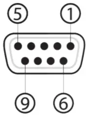 |
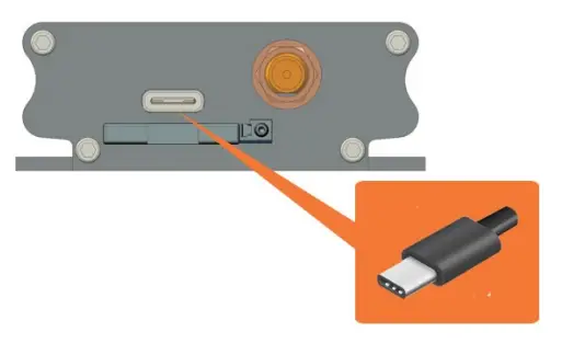
| USB | Type-C connector | n/a |
| I/Os | Analog input (x2) or Digital input (x2) | 0V – 48 Vdc Open collector; 200 mA; 50 Vdc max. |
| Cellular antenna | SMA connector | n/a |
| SIM interface | 2FF SIM 1.8 V/3.0 V | n/a |
| LED indicators | Two (2) – amber, green | n/a |
Lantronix application software (mPACK)
- Dial-up connection
- TCP/UDP permanent client/server or on-demand
- Network connectivity watchdog
- Configurable text and recipients upon the Last Gasp
- DOTA via user’s HTTP server
- Configure via: Terminal program, SMS, and Telnet
For information about working with the mPACK software, refer to M110 Series mPACK Software Command Reference. This is available for download from the M110 series product page at: https://www.lantronix.com/products/m110 seriesmodems/.
Accessories
| Part number | Description |
| Power supply/Power cable | |
| P22E0 | 12V1.25A switching power adapter, with 2pin Molex connector. Euro plug AC cable. |
| P22E2 | 12V1.25A switching power adapter, with 2pin Molex connector. USA plug AC cable. |
| P22E3 | 12V1.25A switching power adapter, with 2pin Molex connector. Australia & NZ plug AC cable. |
| P22E4 | 12V1.25A switching power adapter, with 2pin Molex connector. UK/HK plug AC cable. |
| KDC42 | ACC-CA10 SPARE CABLE (4-PIN) WITH POWER FUSE HS CODE: 8544 4211 |
| Serial and USB cable | |
| KS990 | RS232 CABLE DB9P/M TO DB9P/F L=1000MM |
| KUCA1 | USB 2.0 A/M to USB Type C/M black cable, L=800mm |
| Antennae | |
| A31M0 | JCG017L, Single LTE Antenna, Adhesive remote antenna with 3000mm RG174 cable, SMA male |
| A31H0 | Single LTE Antenna, ultrawideband I-Bar antenna, 3000mm Cable with SMA male, Adhesive mount. |
| A32M0 | Two in one LTE, 2*LTE antenna, 2*3000mm RG174 cable, SMA male |
| A32H0 | Two in one LTE, 2*LTE antenna, 2*3000mm cable, SMA male, adhesive mount |
| Miscellaneous | |
| BR350 | ACC-DIN DIN CLIP HS CODE: 8517 7091 |
| SC485 | RS232 to RS485 converter |
LED Status Indicator
The modem operation status is indicated by two LEDs, which are located on the front side described in the below table.
| LED State | Amber LED | Green LED |
| ON | Solid Cellular connection established | Solid Good CSQ > 10 |
| Blinking Cellular connection established & data transfer in process | Slow blinking No signal, or CSQ < 4 or = 99 | |
| Fast blinking Marginal, CSQ is 4 – 9 | ||
| OFF | No cellular connection | No power |
For further description on CSQ, refer to section 7.3 Received Signal Strength.
Hardware Installation
Inserting SIM card
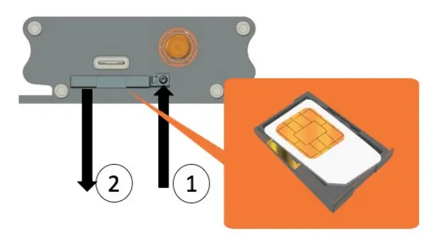
- Eject the SIM tray by pushing the eject button inwards.
- Pull the SIM tray out.
Place the mini-SIM card on the tray with SIM chip facing up, then push the tray back in place carefully
Connecting cellular antenna
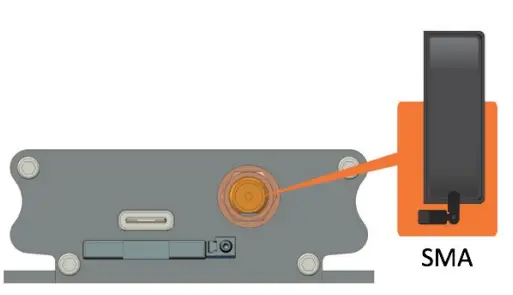
Screw (clockwise) the SMA antenna onto the SMA connector
Connecting USB Type-C cable
Connecting RS-232 DB-9 serial cable
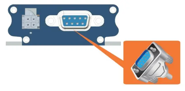
Connect the RS-232 DB-9 serial cable and secure the connection by tightening both thumb knobs on the connector.
Powering the modem
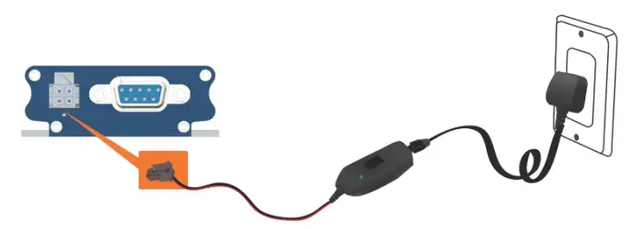
Connect the 4-pin Micro-Fit connector power supply to the modem as shown above.
Communication with the Modem
After all the above setup, communications between the terminal equipment and the modem can now be tested, AT commands can be sent to the modem using a terminal program (i.e., Tera Term) installed on computer for configuring the modem.
Communications test
- Connection between the terminal equipment and the modem can be made using two types of cables.
RS-232 DB-9 Serial cable
or
USB Type-C cable - Configuration of the RS-232 port on the terminal equipment/program should initially be.
Baud-rate: 115,200 bps
Data bits: 8
Parity: None
Stop Bits: 1
Flow control: None - To see if the communications between the terminal program and the modem was established, enter:
AT
and modem will respond with:
OK
Echo Function
The default echo setting is off/disabled (ATE0), to enable the echo function, either.
- Enable “Local echo’ in terminal program
or - Enable the modem echo function (enter ATE1)
In M2M application, it is highly recommended to disable the modem echo function (enter ATE0) to avoid unnecessary traffic between DTE and DCE.
In terminal program, if respond is not displayed after an AT command is entered, recheck the above setting.
If communications cannot be established with the modem, check:
- The RS-232 physical connection
- The RS-232 configuration
After the communications between both has been established, refer to below AT commands for start using the modem.
| AT Command | Description |
| AT+CGMI | To check the module manufacturer identification |
| AT+CPIN=XXXX | To enter a PIN code (if required) (XXXX is actual PIN) |
| AT+CSQ | To verify the received signal strength |
| AT+CREG? | To verify the network registration status |
| ATD<phone number>; | To initiate a voice call |
| ATH | To end the above voice call |
Received Signal Strength
The modem can only establish a call or data session when the received signal strength is sufficient. In terminal window, enter AT+CSQ to see the received signal strength, then the modem will respond in the following format:
+CSQ:<RSSI>, <BER>
or
<RSSI>, <BEP>
or
<RSSI>, <ECNO>
or
<RSSI>, <RSRQ>
Where:
<RSSI> : Received Signal Strength Indication
<BER> : channel Bit Error Rate (GPRS)
<BEP> : channel Bit Error Pattern (EGPRS)
<ECNO> : Energy per Chip Noise ratio (UMTS)
<RSRQ> : Reference Signal Received Quality (LTE)
| RSSI Level | Description |
| 6 to 8 | SMS/Voice |
| 10 to 12 | SMS/Voice/Data |
| 13 to 31 | All above, to maximum RSSI level |
| 99 | Not measurable |
Network Registration
To verify network registration, first ensure the SIM card has been provisioned.
If the model has embedded SIM, first ensure the modem has been activated by the network provider.
To see the network registration status, in terminal program, enter:
AT+CREG?
and refer to the below responses of network registration status.
| Response | Description |
| +CREG: 0,0 | Not registered |
| +CREG: 0,1 | Registered on home network |
| +CREG: 0,2 +CREG:0,3 | Not registered and attempting Registration denied |
| +CREG: 0,5 | Registered on network when roaming |
If it is not registered on the network, check the following.
- If the antenna was attached properly
- The received signal strength (refer to section 8.2)
- If the SIM card was provisioned
PIN Code
To verify, in terminal program, enter:
AT+CPIN?
and refer to the below responses of PIN code status.
| Response | Description |
| +CPIN: READY | PIN code has been entered correctly or not required |
| +CPIN: SIM PIN | PIN code has not been entered or entered incorrectly |
Basic AT command summary
Below table is a summary of basic AT commands, for the full set of commands, refer to M110 Commands Guide.
| Feature | AT Command | Response | Description |
| Check network registration | AT+CREG? | +CREG: 0,0 | Not registered |
| +CREG: 0,1 | Registered on home network | ||
| +CREG: 0,2 | Not registered and attempting | ||
| +CREG: 0,5 | Registered on network and roaming | ||
| Enter PIN code & status | AT+CPIN=XXXX | OK | PIN code accepted |
| *+CME ERROR: 16 | Incorrect PIN code | ||
| AT+CPIN? | Ready | SIM is ready to use | |
| Receive a voice call | ATA | OK | Answer the call |
| Initiate a voice call | ATD<phone number>; | OK | Communication established |
| *+CME ERROR: 11 | PIN code not entered (with +CMEE=1 mode) | ||
| Hang up | ATH | OK | End the call |
| Store settings in EEPROM | AT&W | OK | Configuration settings are stored in non-volatile memory |
*AT+CMEE=1 to enable +CME error result code, otherwise only ‘error’ will be displayed instead.
XXXX is the actual PIN code, if required.
Technical Support
Lantronix offers many resources to support our customers and products at
http://www.lantronix.com/technical-support.
For example, you can browse the knowledge base, open a support issue, find firmware downloads, view tutorials, and more. At this site you can also find FAQs, product bulletins, warranty information, extended support services, and product documentation.
To submit a support request, please use the Lantronix Technical Support portal at https://ltrxdev.atlassian.net/wiki/spaces/LTRXTS/overview (registration required).
To contact Lantronix Sales, look up your local office at https://www.lantronix.com/aboutus/contact/.