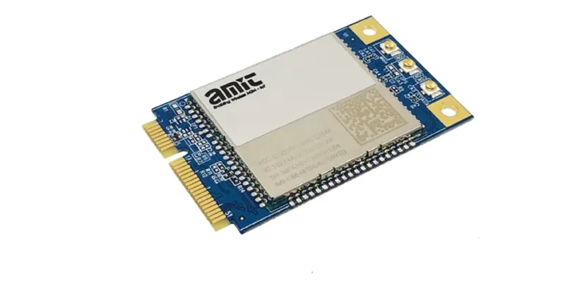
amit MDG100-0TU01 4G Socket Modem
Introduction
Congratulations on your purchase of AMIT’s MDG100 M2M Cellular Socket Modem. With this AMIT cellular modem you have made a great first step in the world of connected Internet of things (IOT) by simply inserting a SIM card from the local mobile carrier into this device to get things connected. This section gives you all the information you need to set up your device.
Main Features:
- Provide 3G/4G cellular connection.
- Deriver ready on Windows 10, Linux and FreeSD.
- Simple Web GUI is used for basic setting and check the 3G/4G status.
- Optional GNSS function for location service.
Before you install and use this product, please read this manual in detail for fully exploiting the functions of this product.
Contents List
Package Contents
#Standard Package
| Items | Description | Contents | Quantity |
|
1 | MDG100-0TU01 4G Socket Modem | 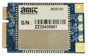 |
1pcs |
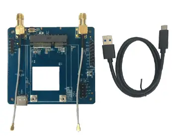
#Optional Package
| Items | Description | Contents | Quantity |
| 1 | Cellular Antenna | 
| 2 pcs |
| 2 | RF Cable SMA to iPex | 100mm / 120mm / 150mm | |
| 3 | Mini-PCIe to USB Loader |
| 1 pcs |
Hardware Configuration
Top View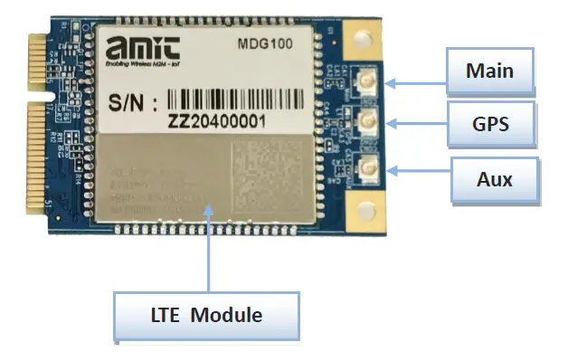
Bottom View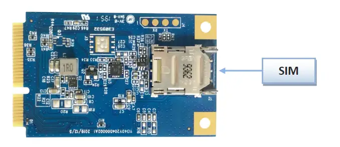
Installation
SYSTEM REQUIREMENTS
| Network Requirements |
|
| Web-based Configuration Utility Requirements | Computer with the following:
Browser Requirements:
|
Federal Communication Commission Interference Statement
This device complies with Part 15 of the FCC Rules. Operation is subject to the following two conditions: (1) This device may not cause harmful interference, and (2) this device must accept any interference received, including interference that may cause undesired operation.
This equipment has been tested and found to comply with the limits for a Class B digital device, pursuant to Part 15 of the FCC Rules. These limits are designed to provide reasonable protection against harmful interference in a residential installation. This equipment generates uses and can radiate radio frequency energy and, if not installed and used in accordance with the instructions, may cause harmful interference to radio communications. However, there is no guarantee that interference will not occur in a particular installation. If this equipment does cause harmful interference to radio or television reception, which can be determined by turning the equipment off and on, the user is encouraged to try to correct the interference by one of the following measures:
- Reorient or relocate the receiving antenna.
- Increase the separation between the equipment and receiver.
- Connect the equipment into an outlet on a circuit different from that to which the receiver is connected.
- Consult the dealer or an experienced radio/TV technician for help.
FCC Caution: Any changes or modifications not expressly approved by the party responsible for compliance could void the user’s authority to operate this equipment.
This transmitter must not be co-located or operating in conjunction with any other antenna or transmitter.
FOR PORTABLE DEVICE USAGE (<20m from body/SAR needed)
Radiation Exposure Statement:
The product comply with the FCC portable RF exposure limit set forth for an uncontrolled environment and are safe for intended operation as described in this manual. The further RF exposure reduction can be achieved if the product can be kept as far as possible from the user body or set the device to lower output power if such function is available.
FOR MOBILE DEVICE USAGE (>20cm/low power)
Radiation Exposure Statement:
This equipment complies with FCC radiation exposure limits set forth for an uncontrolled environment. This equipment should be installed and operated with minimum distance 20cm between the radiator & your body.
FOR COUNTRY CODE SELECTION USAGE (WLAN DEVICES)
Note: The country code selection is for non-US model only and is not available to all US model. Per FCC regulation, all WiFi product marketed in US must fixed to US operation channels only.
Product Information
The following product information is required to be presented in product User Manual
Frequency Band & Maximum Power
- Frequency Band for Cellular Connection (for EC25-EU version)
| Band number | Operating Frequency | Max output power |
| LTE FDD BAND 1 | Uplink: 1920-1980 MHz Downlink: 2110-2170 MHz | 23.1 dBm |
| LTE FDD BAND 3 | Uplink: 1710-1785 MHz Downlink: 1805-1880 MHz | 23.0 dBm |
| LTE FDD BAND 7 | Uplink: 2500-2570 MHz Downlink: 2620-2690 MHz | 22.8 dBm |
| LTE FDD BAND 8 | Uplink: 880-915 MHz Downlink: 925-960 MHz | 23.2 dBm |
| LTE FDD BAND 20 | Uplink: 832-862 MHz Downlink: 791-821 MHz | 23.5 dBm |
| LTE FDD BAND 28A | Uplink: 704 -723 MHz Downlink: 759 – 778MHz | 23 dBm |
| LTE FDD BAND 38 | Uplink: 2570-2620 MHz Downlink: 2570-2620 MHz | 21.7 dBm |
| LTE FDD BAND 40 | Uplink: 2300-2400 MHz Downlink: 2300-2400 MHz | 21.5 dBm |
| WCDMA BAND 1 | Uplink: 1920-1980 MHz Downlink: 2110-2170 MHz | 23.3 dBm |
| WCDMA BAND 8 | Uplink: 880-915 MHz Downlink: 925-960 MHz | |
| E-GSM | Uplink: 880-915 MHz Downlink: 925-960 MHz | 32.9 dBm |
| DCS | Uplink: 1710-1785 MHz Downlink: 1805-1880 MHz | 29.9 dBm |
- Frequency Band for Cellular Connection (for Quectel EC25-AF version)
| Band number | Operating Frequency | Max output power |
| LTE FDD BAND 2 | Uplink: 1850-1910 MHz Downlink: 1930-1990 MHz | 23.86 dBm |
| LTE FDD BAND 4 | Uplink: 1710-1755 MHz Downlink: 2110-2155 MHz | 23.82 dBm |
| LTE FDD BAND 5 | Uplink: 824-849 MHz Downlink: 869-894 MHz | 23.46 dBm |
| LTE FDD BAND 12 | Uplink: 699-716 MHz Downlink: 729-746 MHz | 23.75 dBm |
| LTE FDD BAND 13 | Uplink: 777-787 MHz Downlink: 746-756 MHz | 23.86 dBm |
| LTE FDD BAND 14 | Uplink: 788-798 MHz Downlink: 758-768 MHz | 23.86 dBm |
| LTE FDD BAND 66 | Uplink: 1710-1780 MHz Downlink: 2100-2200 MHz | 23.34 dBm |
| WCDMA BAND 2 | Uplink: 1850-1910 MHz Downlink: 1930-1990 MHz | 23.3 dBm |
| WCDMA BAND 4 | Uplink: 1710-1755 MHz Downlink: 2110-2155 MHz | |
| WCDMA BAND 5 | Uplink: 824-849 MHz Downlink: 869-894 MHz |
DoC Information
You can get the DoC information of this product from the following URL:
http://www.amitwireless.com/products-doc/
Manufacture Information
Manufacture Name: AMIT Wireless Inc.
Manufacture Address: No. 28, Lane 31, Sec. 1, Huandong Rd., Sinshih Dist., Tainan 74146, Taiwan
Hardware Installation
This chapter describes how to install and configure the hardware
Insert the SIM Card
WARNING: BEFORE INSERTING OR CHANGING THE SIM CARD, PLEASE MAKE SURE THAT POWER OF THE DEVICE IS SWITCHED OFF.
SIM card slot is located in the botton area of MDG100 series. You need to insert the SIM card first and mount the device on Mini-PCIe socket if your host board has no SIM slot. Please follow below instructions to install or remove a SIM card.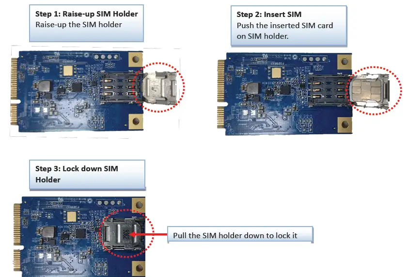
Connecting to the Host Board
The MDG100 is a modem device with Miin-PCIe interface with USB 2.0. User needs to put the card on a Mini-PCIe socket and link cellular antenna on the modem to enable the cellular connection.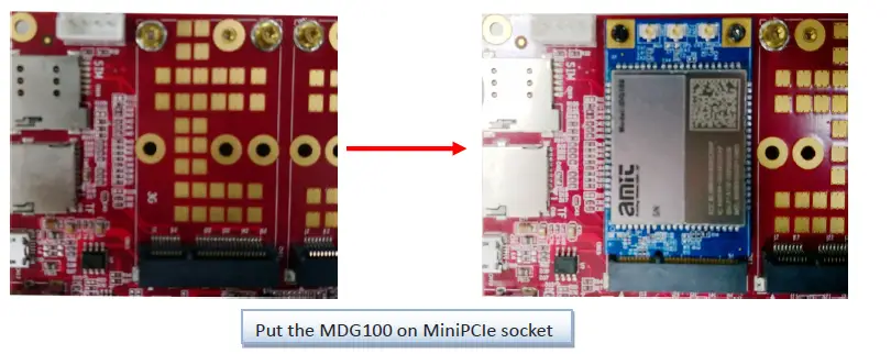 User can check device information in serval different OS as below.
Windows
 Linux
Linux 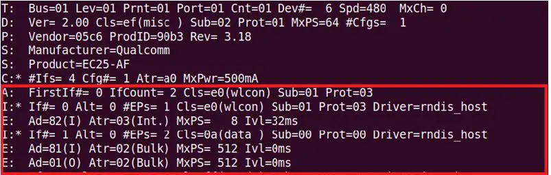
Setup by Configuring WEB UI
User can browse web UI to configure the modem device.
Type in the IP Address (http://172.16.0.1)1 When you see the login page, enter the user name and password and then click ‘Login’ button. The default setting for both username and password is ‘admin’ 2.
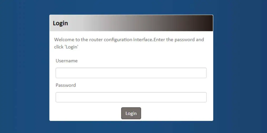
- The default LAN IP address of this device is 172.16.0.1. If you change it, you need to login by using the new IP address.
- For security concern, the login process will force user to change default password at the first time.
Setup
The MDG100 series connect to a machine via USB 2.0 interface on Mini-PCIe socket for 3G/4G network connection. MDG100 provides NAT and Modem functions and helps the network application more flexible.
Network
| Network Page Item | Description |
| Device Mode | Set the unit operating mode |
| Cellular | Set the parameter for cellular network. |
| Ethernet | Set the IP of LAN side and DHCP service |
| Port Forwarding | Enable specified port or protocol for service on connected device. |
| DDNS | Register a dynamic host name for the unit. |
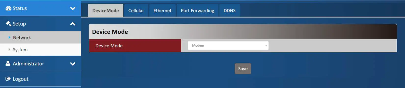
Device Mode
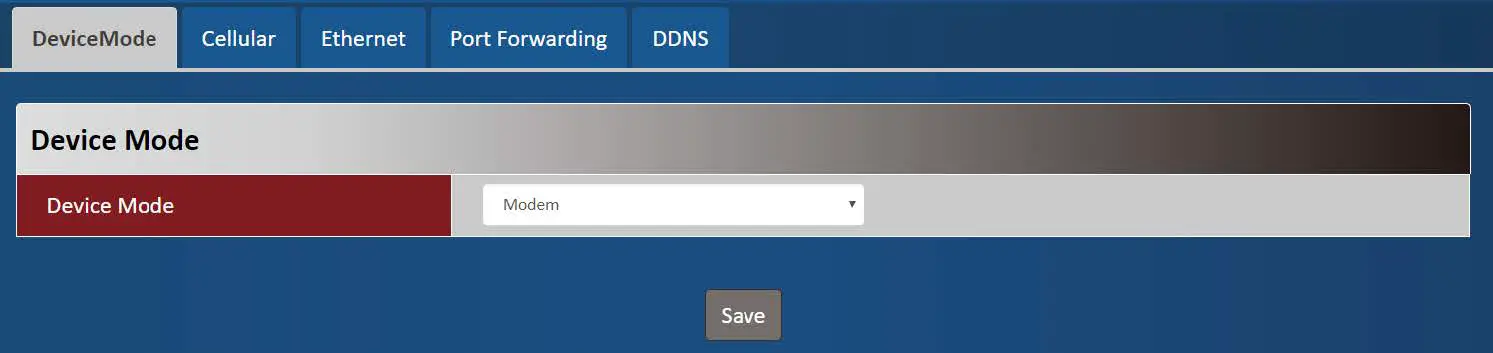
| Device Mode Item | Value setting | Description |
| Device Mode |
| NAT The unit will provide a NAT service and provide a simple firewall for the connected device.Modem The unit will pass the cellular IP to connected device on LAN side. |
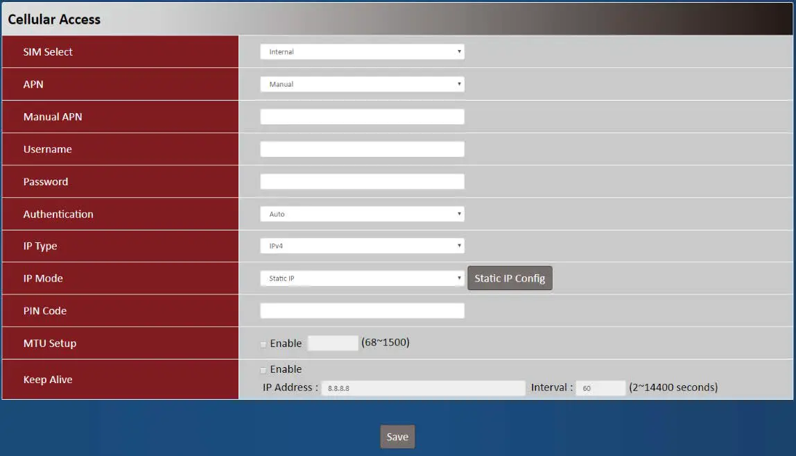
Cellular
| Device Mode Item | Value setting | Description |
| SIM Select | 1. A Must filled setting 2. By default Internal is selected | Auto The unit will switch SIM path automatically. Internal The unit will use SIM slot on board. External The unit will use SIM path via Mini-PCIe interface. |
| APN | 1. A Must filled setting 2. By default Auto is selected | Auto The unit will detect the SIM and set an APN from internal database. Manual User must set APN manually. |
| Manual APN |
| Enter the APN you want to use to establish the connection. This is a must-filled setting if you selected Manual APN as APN scheme. |
| Username |
| Enter the optional username settings if your ISP provided such settings to you. |
| Password |
| Enter the optional Password settings if your ISP provided such settings to you. |
| Authentication |
| Select PAP (Password Authentication Protocol) and use such protocol to be authenticated with the carrier’s server. Select CHAP (Challenge Handshake Authentication Protocol) and use such |
| protocol to be authenticated with the carrier’s server. When Auto is selected, it means it will authenticate with the server either PAP or CHAP. | ||
| IP Mode |
| Dynamic IP The unit will get IP from cellular service..Static IP The unit will set IP according Static IP Config. |
| IP Type |
| Specify the IP type of the network service provided by your 3G/4G network. It can be IPv4, IPv6, or IPv4v6. |
| PIN Code |
| Enter the PIN (Personal Identification Number) code if it needs to unlock your SIM card. |
| MTU Setup |
| Check the Enable box to enable the MTU (Maximum Transmission Unit) limit, and specify the MTU for the 3G/4G connection. MTU refers to Maximum Transmission Unit. It specifies the largest packet size permitted for Internet transmission. Value Range: 68 ~ 1500. |
| Keep Alive |
| Check the Enable box to activate the keepalive function. Input IP Address and interval to send an ICMP packet to check the network status. |
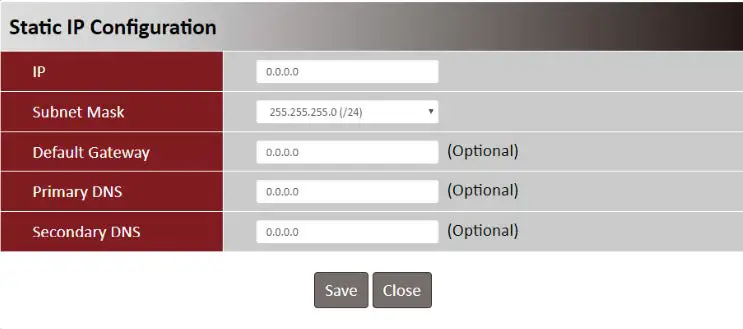
| Static IP Configuration Item Value setting | Description | |
| IP |
| The Static IP Address setting of this unit. |
| Subnet Mask | 255.255.255.0 (/24) is set by default | The Subnet Mask of this configed static IP. |
| Default Gateway |
| The gateway setting of this configed static IP. |
| Primary DNS |
| Assigned DNS server of this configed static IP. |
| Secondary DNS | 1. IPv4 format. | Assigned DNS server of this configed static IP. |
Ethernet
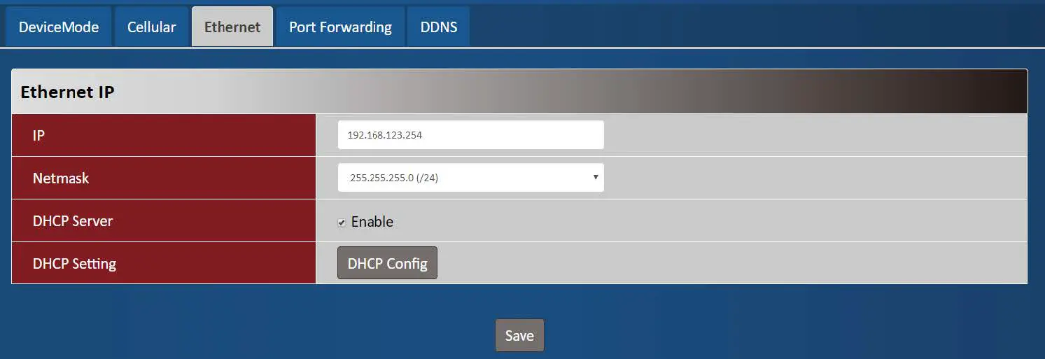
| Ethernet IP Item | Value setting | Description |
| IP |
| The LAN IP Address of this unit. |
| Netmask | 255.255.255.0 (/24) is set by default | The Subnet Mask of this unit. |
| DHCP Server | The box is checked by default. | Click Enable box to activate DHCP Server. |
| DHCP Setting | N/A | Click DHCP Config button to pop-up the DHCP Setting page. |
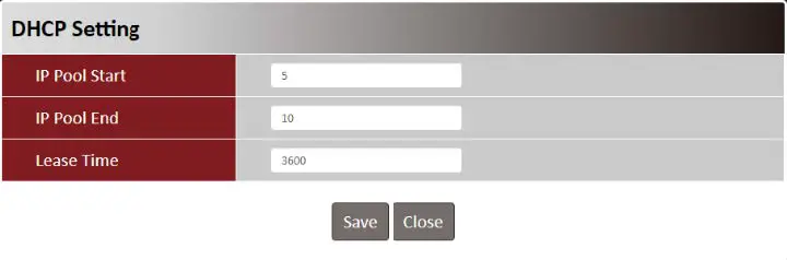
| DHCP Setting Item | Value setting | Description | ||||
| IP Pool Start |
| The IP Pool of this DHCP Server. It is Starting Address entered in this field. | ||||
| 2. A Must filled setting | ||||||
| IP Pool End |
| The IP Pool of this DHCP Server. It is Ending Address entered in this field. | ||||
| Lease Time |
| The Lease Time of this DHCP Server. Value Range: 300 ~ 604800 seconds. | ||||
Port Forwarding
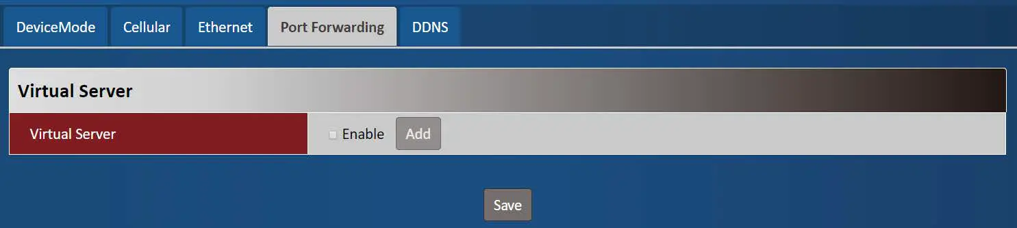
| Virtual Server Item | Value setting | Description |
| Virtual Server | The box is unchecked by default | Check the Enable box to activate this port forwarding function Click Add will pop-up Virtual Server Rule Configuration page. |
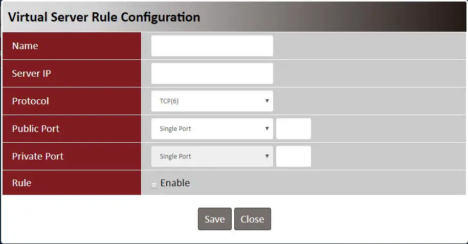
| Virtual Server Rule Configuration Item Value setting | Description | |
| Name |
| The name of current rule |
| Server IP | A Must filled setting | This field is to specify the IP address of the interface selected in the WAN Interface setting above. |
| Protocol | A Must filled settin | When “TCP(6)” is selected It means the option “Protocol” of packet filter rule is TCP. Public Port selected a predefined port from Well-known Service, and Private Port is the same with Public Port number. Public Port is selected Single Port and specify a port number, and Private Port can be set a Single Port number. Public Port is selected Port Range and specify a port range, and Private Port can be selected Single Port or Port Range. Value Range: 1 ~ 65535 for Public Port, Private Port. When “UDP(17)” is selected It means the option “Protocol” of packet filter rule is UDP. Public Port selected a predefined port from Well-known Service, and Private Port is the same with Public Port number. Public Port is selected Single Port and specify a port number, and Private Port can be set a Single Port number. Public Port is selected Port Range and specify a port range, and Private Port can be selected Single Port or Port Range. Value Range: 1 ~ 65535 for Public Port, Private Port. When “TCP(6) & UDP(17)” is selected It means the option “Protocol” of packet filter rule is TCP and UDP. Public Port selected a predefined port from Well-known Service, and Private Port is the same with Public Port number. Public Port is selected Single Port and specify a port number, and Private Port can be set a Single Port number. Public Port is selected Port Range and specify a port range, and Private Port can be selected Single Port or Port Range. Value Range: 1 ~ 65535 for Public Port, Private Port. When “User-defined” is selected It means the option “Protocol” of packet filter rule is User-defined. For Protocol Number, enter a port number. |
| 1. An optional filled | ||
| Rule | setting | Check the Enable box to activate the rule. |
| 2.The box is unchecked | ||
| by default. | ||
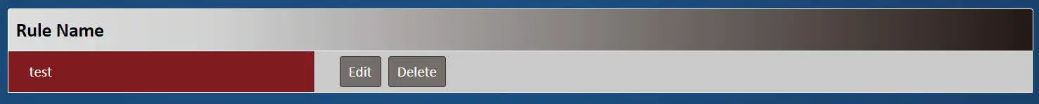
| Virtual Server – Rule Name Item Value setting Description |
| Clicl “Edit” button to pop-up Virtual Server Rule Configuration page to edit Rule name N/A the rule. Click “Delete” button to delete this rule |
DDNS
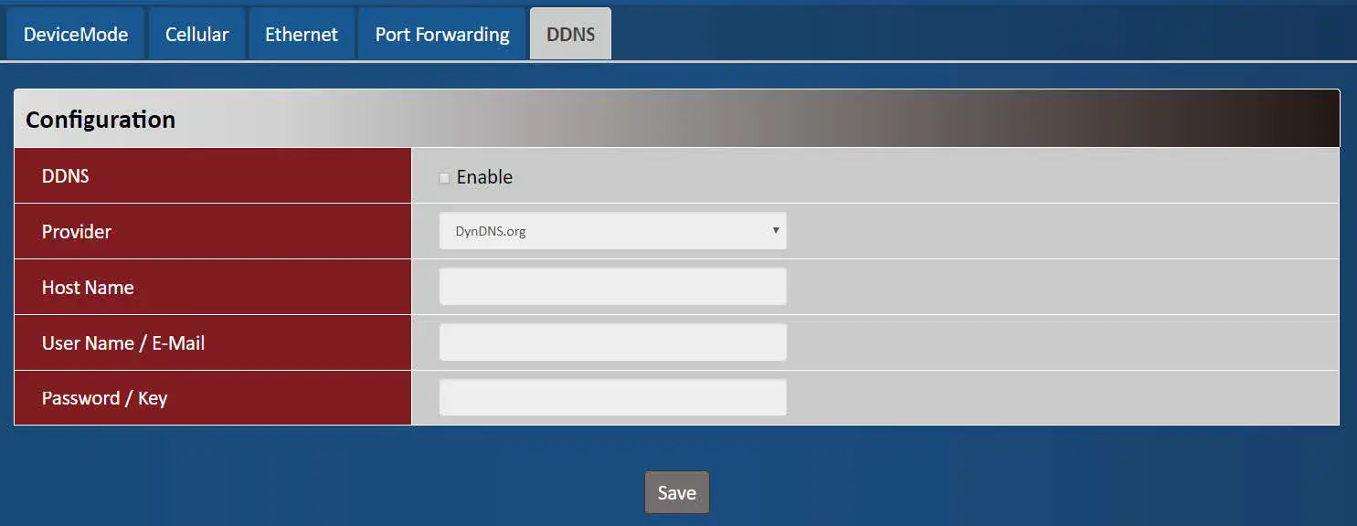
| DDNS Item | Value setting | Description |
| DDNS | The box is unchecked by default | Check the Enable box to activate this function. |
| Provider | DynDNS.org is set by default | Select your DDNS provider of Dynamic DNS. It can be DynDNS.org, NO- IP.com, TZO.com etc… |
| Host Name |
| Your registered host name of DDNS Service. Value Range: 0 ~ 63 characters. |
| User Name / E-Mail |
| Enter your User name or E-mail addresss of DDNS Service. |
| Password / Key |
| Enter your Password or Key of DDNS Service. |
System
This section provides the configuration of system features.
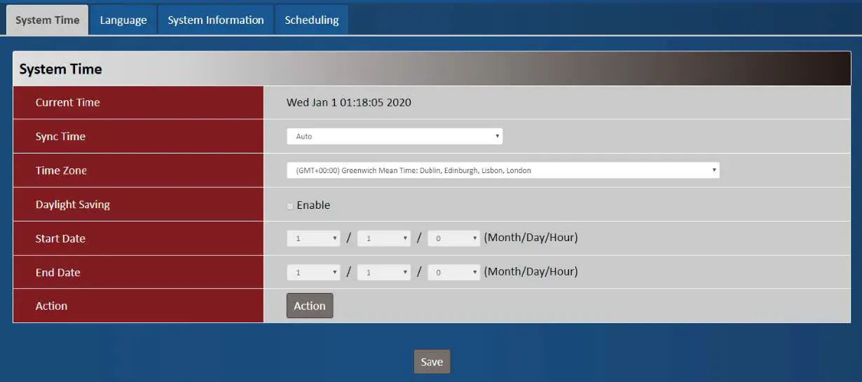
- System Time

| System Time Item | Value setting | Description |
| Current Time | N/A | Show the current time of the unit. |
| Sync Time |
| When select Auto, unit will sync the time via cellular cell, and then try to use NTP if cellular cell doesn’t provide time information. When select NTP, the unit will sync time via ntp service. |
| Time Zone |
selected by default. | Select a time zone where this device locates. |
| Daylight Saving |
| Check the Enable button to activate the daylight saving function. When user enabled this function, user has to specify the Start Date and End Date for the daylight saving time duration. |
| Start Date | N/A | Start time for Daylight Saving. |
| End Date | N/A | End Time of Daylight Saving. |
| Action | N/A | Click Action to sync time immediately |
Language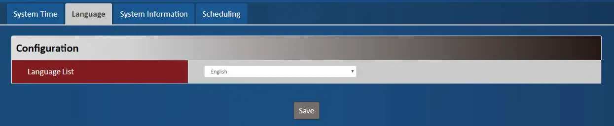
| Language Item | Value setting | Description |
| Language List |
| Language setiing of the WebGUI. |
System Information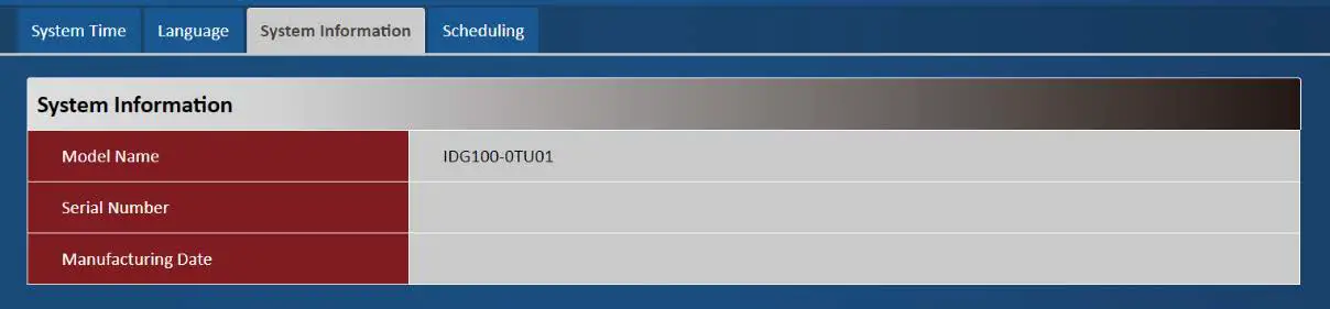
| System Information Item | Value setting | Description |
| Model Name | N/A | Show the model name of the device |
| Serial Number | N/A | Show the serial number of the device |
| Manufacturing Datte | N/A | Show the manufacturing date of the device. |
Scheduling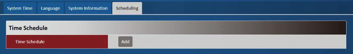
| Scheduling Item | Value setting | Description |
| Time Schedule | N/A | Press Add to create a schedule rule for system. |
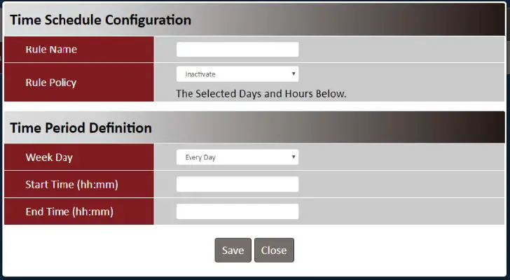
| Time Schedule Configuration Item Value Setting | Chapter 3 Administrator 3.1 Manager Description | |
| Rule Name | String: any text | Set rule name |
| Rule Policy | Default Inactivate | Inactivate/activate the function been applied to in the time period below |
| Time Period Definition Item Value Setting | Description | |
| Week Day | Select from menu | Select everyday or one of weekday |
| Start Time | Time format (hh :mm) | Start time in selected weekday |
| End Time | Time format (hh :mm) | End time in selected weekday |
Administrator
Manager
This section provides configuration to manage the device.
FW Upgrade
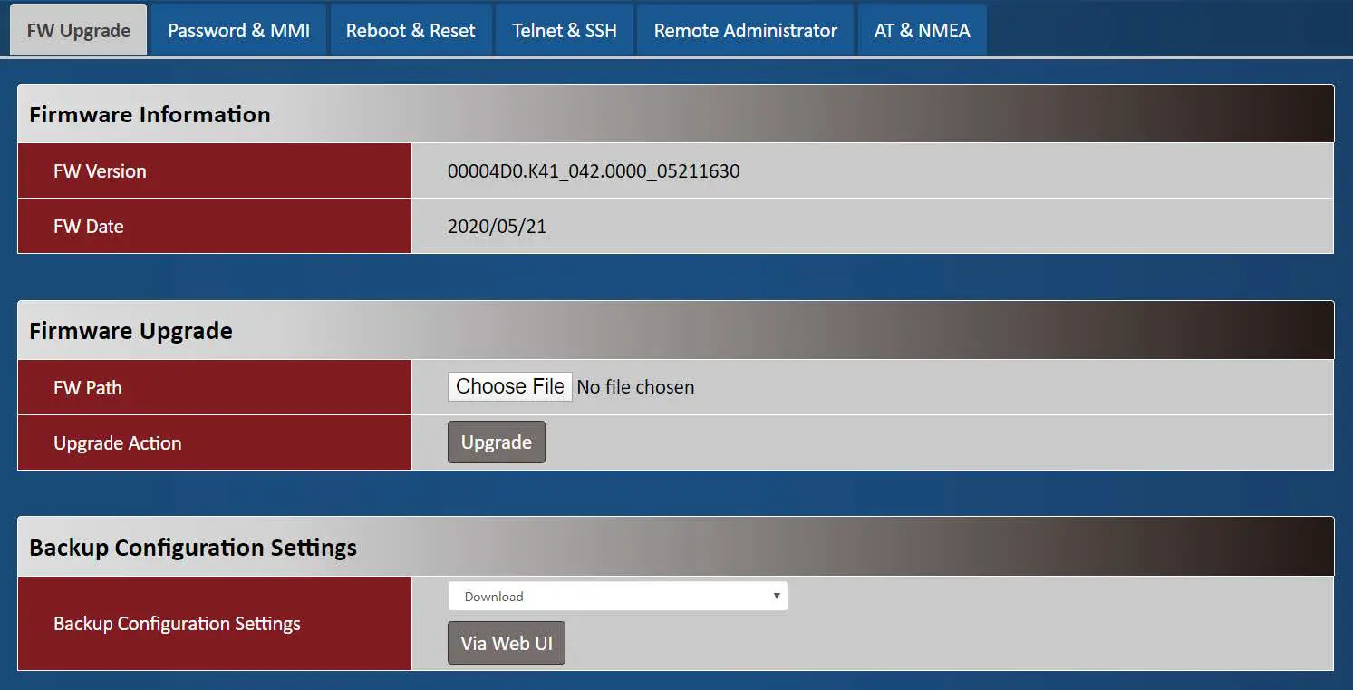
| Firmware Information Item Value setting | Description | |
| FW Version | N/A | It displays the firmware version of the product |
| FW Date | N/A | It displays the build time of the firmware |
| Firmware Upgrade Item | Value setting | Description |
| FW Path | N/A | Select firmware file to be upgraded |
| Upgrade Action | N/A | Click Upgrade button to start upgrade process with selected FW |
| Backup Configuration Settings Item Value setting Description |
| Backup Configuration N/A Select “Download” to backup current configuration to a file. Settings Select “Upload” to restore configuration from selected file. |
Password & MMI
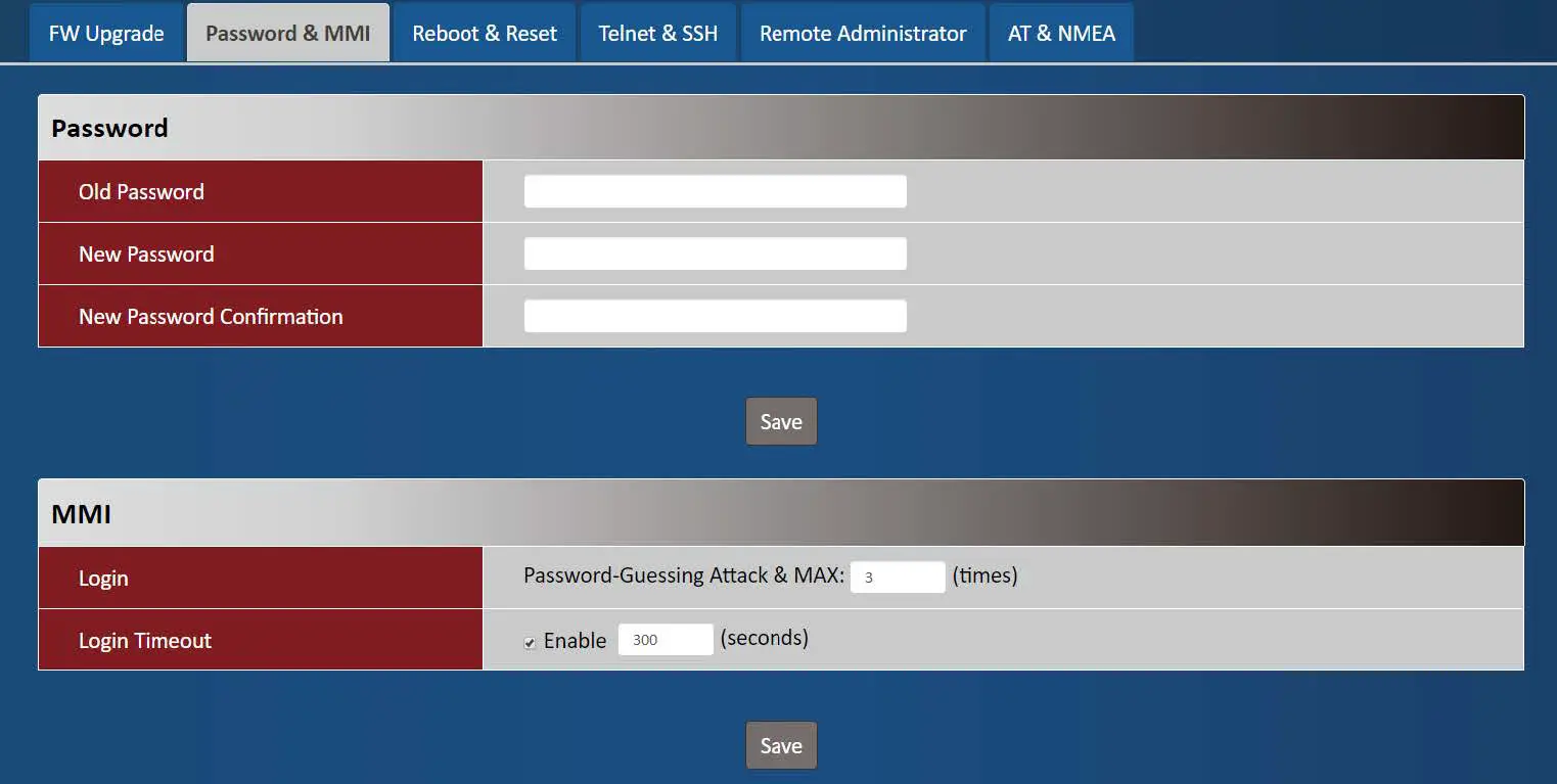
| Password Item Value setting Description |
|
| New Password String: any text Enter new password |
| New Password String: any text Enter new password again to confirm Confirmation |
| MMI Item | Value setting | Description |
| Login | 3 times is set by default | Enter the login trial counting value. Value Range: 3 ~ 10. If someone tried to login the web GUI with incorrect password for more than the counting value, an warning message “Already reaching maximum Password-Guessing times, please wait a few seconds!” will be displayed and ignore the following login trials. |
| Login Timeout | The Enable box is checked, and 300 is set by default. | Check the Enable box to activate the auto logout function, and specify the maximum idle time as well. Value Range: 30 ~ 65535. |
Reboot & Reset
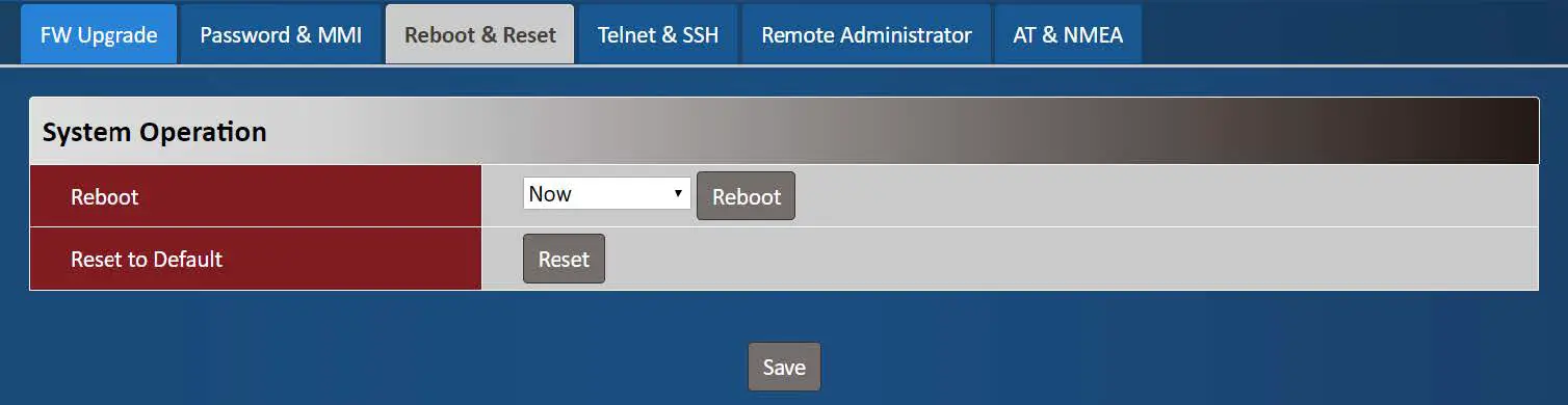
| Device Mode Item | Value setting | Description |
| Reboot | N/A | Chick the Reboot button to reboot the unit immediately |
| Reset to Default | N/A | Click the Reset button to reset the device configuration to its default value. |
Telnet & SSH
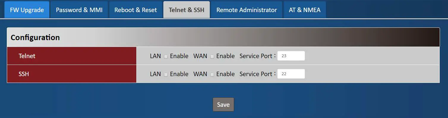
| Telnet & SSH Item | Value setting | Description |
| Telnet |
| Check the Enable box to activate the Telnet function for connecting from LAN or WAN interfaces. You can set which number of Service Port you want to provide for the corresponding service. It doesn’t command to enable WAN site if the device service in public IP. Value Range: 1 ~65535. |
| SSH |
| Check the Enable box to activate the SSH Telnet function for connecting from LAN or WAN interfaces. You can set which number of Service Port you want to provide for the corresponding service. Value Range: 1 ~65535. |
Remote Administrator
| Remote Administrator Host Definition Item Value setting Description |
| Remote Administrator N/A Press “Add” to set a remote administrator rule Host Definition |
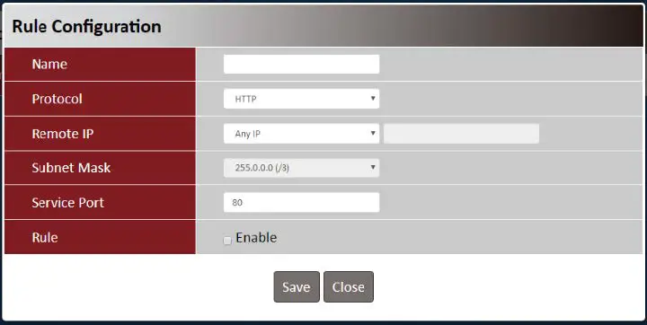
| Rule Configuration Item Value setting | Description | |
| Name | String: any text | Set rule name |
| Protocol | HTTP is set by default | Select HTTP or HTTPS method for router access. |
| Remote IP | A Must filled setting | This field is to specify the remote host to assign access right for remote access. Select Any IP to allow any remote hosts Select Specific IP to allow the remote host coming from a specific subnet. |
| Subnet Mask | N/A | An IP address entered in this field and a selected Subnet Mask to compose the subnet if Remote IP set in Specific IP. |
| Service Port | 1. 80 for HTTP by default | This field is to specify a Service Port to HTTP or HTTPS connection. |
| 2. 443 for HTTPS by Value Range: 1 ~ 65535. default |
| Rule The box is unchecked by Click Enable box to activate this rule. default. |
AT & NMEA
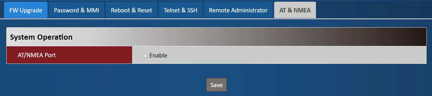
| AT & NMEA Item | Value setting | Description |
| AT/NMEA Port | Default value is disabled | Enable this function to have additional AT and NMEA ports of the modem. AT port provides interface for user to send standard AT command(3GPP TS 27.005 / 27.007). NMEA port will informs location satat if user enable GNSS function. |


