![]()
AMPLIMAX
EPRL16
USER MANUAL
Maximum performance for Internet in low or nonexistent locations.
EASY INTERNET
BEFORE USING
 ATTENTION
To avoid physical and functional damage, do not open this device beyond connections compartment. Prevent it from falls and / or violent shocks. Always use its original font. Avoid using this product or the devices connected to it during storms. There is a risk of electric shock due to lightning strike.
 IMPORTANT
This product is compatible with the nano size SIM card.
Never insert the adapter that came with the product without the SIM card to avoid damaging the product’s connector.
PLEASE NOTE:
The source voltage for this product is 24 VDC. As this value is higher than that supported by most products on the market, be careful not to connect it to other equipment, otherwise it will be damaged.
BASIC REQUIREMENTS
- Network cable (RJ45) to connect Amplimax to POE – lenght depends on each installation.
- SIM Card nano (with active data plan).
PLEASE NOTE: Never insert or remove the SIM card in the slot with the device on. This could damage it.
ABOUT THE RANGE OF THIS PRODUCT
The range of AMPLIMAX depends on a number of factors, such as: frequency of operation, location and height of installation, terrain profile, number and type of obstacles between the product and the cell tower, rain and reflections. Due to these factors it is not possible to predict it accurately. Based on the experiences already made and published in the literature, we present below an estimated comparison between two scenarios:
Scenario 1: USB modem connected indoors.
Scenario 2: AMPLIMAX ELSYS installed on the roof, at a height of 5 meters.
The table below describes the improvement in the range and level received from AMPLIMAX in scenario 2 regarding to the USB modem in scenario 1:
| Frequency band | 850 MHz |
| Received level (mW) | Up to 200X more than the 3G / 4G USB modem |
| Range (km) | Up to 5X more than the 3G / 4G USB modem |
ATTENTION
This product has an active data collection function. For more information or deactivation, refer to the item “Data Collection” in this manual.
TECHNICAL SPECIFICATIONS
| Supply voltage: • 12 to 24VDC Frequency Bands: 4G: 600*(B71), 700 (B12, B13, B14), 850(B5), 1700 (B4, B66), 1900 (B2) MHz 3G: 850 (B5), 1700 (B4) and 1900 (B2) MHz Rate of data transmission: • LTE R9: (DL) 70Mbps Max and (UL) 50Mbps Max • HSPA R6: (DL) 21 Mbps Max and (UL) 5.76Mbps Max • UMTS R99: (DL) 384kbps Max and (UL) 384kbps Max MIMO 2×2 on the 4G downlink at the bands B4 and B66 Transmission power: • Class 3 (24dBm + 1 / -3dB) for UMTS • Class 3 (23dBm ± 2dB) for LTE Operation temperature: • External unit: 14°F ~ 140°F • Power supply and POE: 32°F ~ 104°F Storage temperature: • -4°F ~ 158°F Ethernet Port • RJ45 connector • IEEE 802.3 – Ethernet 10 / 100Mbps | Maximum length of RJ45 cable: • With original source 24 VDC / 0.75A: 328ft • With 12 VDC / 1.5 A source: 50ft • With 12 VDC / 1.5 A battery: 50ft Factory configured IP address • 192.168.10.254 Main directional antenna • 700 up to 2700 MHz • Vertical polarization • Gain: 700 to 960 MHz: 6 dBi 1710 to 1910 MHz: 7.9 dBi 1920 to 2700 MHz: 10 dBi 10 dBi (1920 MHz), 10 dBi (2310 MHz) and 8 dBi (2700 MHz) Directional diversity antenna • Bands: B4 and B66 (downlink) • Horizontal polarization • Gain: 8 dBi (2110 up to 2200 MHz) Sim Card Slot • Accepts nano Sim Card only |
*Obs.: The band 600 MHz is the only one that is not covered by the product internal antenna. So, for that band, the use an external antenna is mandatory.
PRODUCT DETAILS
AMPLIMAX CONNECTIONS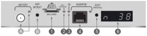
- Entrance to the SIM Card of the chosen carrier. Inserting until you feel a “click”
- CELL NETWORK LED – Flashing, with time on longer than off, indicates connection established. Flashing, with off time longer than on, indicates network search.
- 4G LED – On indicates 4G connection. Off indicates 3G connection
- RJ45 connection – for network cable up to 328 ft.
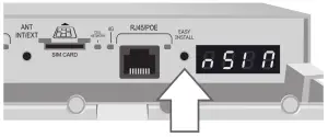
- EASY INSTALL key – When pressed for 7 seconds, it performs the factory reset / Without the Sim Card it starts the blind search / With the Sim Card it starts the signal location
- Display (4 digits) – Displays equipment information
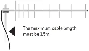
A. Connector for external antenna and LED indicator: Internal Antenna – LED off /External Antenna – LED on. Use only in extreme cases and with cable up to 1.5m (max.).
B. Switching key between internal and external antenna.
POE INJECTOR CONNECTIONS
POE CONNECTIONS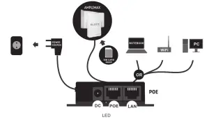
DC: Power supply 24V / 0.75A (dual voltage 100 ~ 240V).
POE: Network cable up to 100 m. Connects to AMPLIMAX.
LAN: Network cable to connect: PC, AP, Wi-Fi Router or Switch.
LED: Indicates source on and connected to the POE.
INSTALLATION
The installation of AMPLIMAX must be done according to the simplified diagram below:
GENERAL CONNECTIONS MAP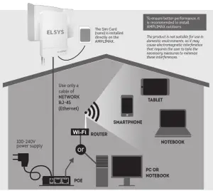
Preferably, the installation must be done according to the following steps:
NETWORK CABLE ASSEMBLY
Provide a network cable that will connect the POE to the AMPLIMAX, with direct assembly, that is, with the same two ends. If the cable is passed through conduits, pass it before crimping its terminals. The use of good connectors and cable is essential (it is recommended to use shielded CAT5e cable if the installation is external), especially since the cable also conducts the product supply. The correct assembly of this cable is essential for the proper functioning of the product and also to avoid damaging it. For more information on cable assembly, check the Cable Assembly section in this manual. Use cable approved by FCC, especially if the length is greater than 33 ft.
POE INSTALLATION
The POE must be installed indoors and connected to the source, computer, telephone and AMPLIMAX, as shown in the diagram above.
EASY INSTALL
BLIND SEARCH OF CARRIERS
If you want to know the cellular networks available at the installation site, perform the following steps:
Before mounting the reflector on the AMPLIMAX and before connecting the SIM Card, take the AMPLIMAX cabinet to a location close to the final installation. Remove the AMPLIMAX cover and connect the network cable from the POE, as shown below: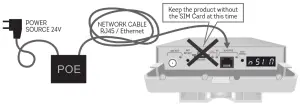
As soon as the product is turned on, the display must show the “Boot” ( ![]() ) message followed by “Load” (
) message followed by “Load” (![]() ) and “—” Soon after, it displays the power of supply that arrives at the product, which must be greater than or equal to 9V (
) and “—” Soon after, it displays the power of supply that arrives at the product, which must be greater than or equal to 9V ( ![]() ) Make sure that the product is missing the SIM Card and wait for the display show the message “nSIM” (
) Make sure that the product is missing the SIM Card and wait for the display show the message “nSIM” (![]() )
)
Then, press the “Easy Install” key, so that the equipment starts the “Blind Search”. Lift the product and hold it at its bottom, so as not to impair the functioning of your antenna, as shown in the figure on the side: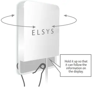
The “Blind Search” may take a few minutes, depending on the location and configuration of the product. At the end of this period, the display will show the list of available cellular networks, organized by technology: (E.g.: 4G and 3G) and the level of each one. (See list of networks in OPERATION). If no cellular networks are found, try searching elsewhere. The search will only be performed on the technologies (4G and 3G) selected on the AMPLIMAX configuration web page. The factory setting will search for 4G and 3G networks.
Once the “Blind search” has started, the process cannot be interrupted, and it must wait until the results obtained are displayed. If you wish to interrupt the display of the Blind Search results, simply press the “Easy Install” key again. Generally, the better the carrier level, the better the data rate. Keep in mind, however, that when the reflector is fitted and the correct pointing is made, the level of the selected carrier tends to increase significantly.
Note: In some regions, an carrier that has a cellular network may rent its infrastructure to another carrier. In this way, the same signal will be shared by the two carriers. In this case, the search will show only the carrier name that owns the cellular network.
BEST SIGNAL FINDER
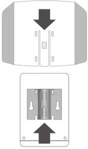
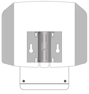
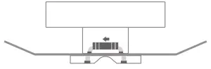
FIT THE REFLECTOR TO THE CABINET (TOP TO BOTTOM)
- Fit the reflector to the back of the cabinet.

- It must sliding like a drawer, up to the limit of the path. At the end, must activate the lock with a “click”.

- The top view must appear as in the figure below.

SIM CARD POSITIONING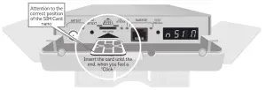
CAUTION: To insert or remove the Sim Card, turn off the product or remove the network cable.
ANTENNA POINTING
Once the carrier has been chosen and the reflector is correctly fitted, remove the AMPLIMAX cover and insert the SIM Card in the correct position. Then reconnect the network cable from the POE, as shown according the figure.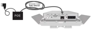
As soon as the product is turned on, the display must show the message “Boot”, followed by “Load”, “- – – -” and the supply voltage. If the product identifies a cellular network, it will display its name, followed by its band, signal level and technology in a cyclical manner.
After the supply voltage disappears, press the “Easy Install” button, which will make the equipment indicate the level received through the display in real time. Note: When one carrier rents the cellular network from another, the display indicates the name of the proprietary network.
The value will be between 00 and 99%. In addition, there is an audible indication that is activated at that time. The more continuous the sound, the stronger the signal. If AMPLIMAX is not yet registered on the cellular network, the display will indicate the flashing message “BUSC.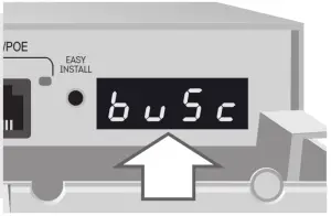 Slowly rotate the AMPLIMAX pointing, trying to identify the angle that allows the best reception level. Vary it position, trying to get away from possible obstacles. In general, the higher it is installed, the better the signal level.
Usually, a level above 30% already allows the use of the product. Even so, the higher the level received, the better it can be the stability of your Internet. It is important to always seek the highest possible signal level.
Once the best position and pointing has been identified, just press the “Easy Install ” key once to exit this mode.
PRODUCT FASTENING ON MASTS
See drilling templates on the final page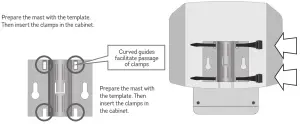
ON WALLS
The wall installation can be done with two screws for S6, S7 or S8 bushings. Fix the two screws on the wall 7.2 cm apart (center-to-center), as the figure below:
When screwing the screws, leave a space of approximately 4 mm from the wall. Then, fit the AMPLIMAX to these screws through the rear holes as in the figure: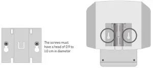
VERIFYING THE INSTALLATION
Typically, the installation will be completed in this step. After energizing the product, wait 1 and a half minutes. Check, then, that it is already possible to browse the Internet by connecting the network cable (RJ-45) to a notebook, PC, Access Point or Wi-Fi router. If you are unable to navigate, proceed to the next step.
SETTING THE IP ON THE COMPUTER
(Only if necessary).
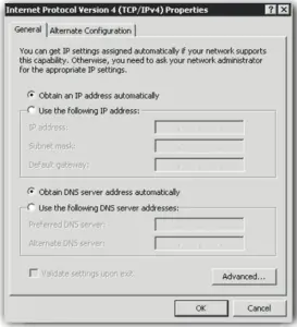
Make sure your local network card is enabled to receive IP automatically. The information below is for Windows 7:
- Select the Start / Control Panel / Network and Internet / Network and Sharing Center / Change adapter settings option.
- With the right mouse button, select Local Connection and go to Tools.
- Double click on “TCP / IP Protocol Version 4”.
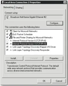
The screen on the side will be displayed:
- Make sure that the “Obtain an IP address automatically” option is enabled.
- Press OK and exit all screens.
Enter your browser and start using the Internet. Advanced setting can be made through the product setting page, as described in the item “WEB Setting Page”.
OPERATION
DISPLAY AND WEB PAGE
OPERATING MODE
Monitoring – With the inserted Sim Card it displays: carrier, band, signal level and technology.
Blind Search – Without the inserted Sim Card it displays: animation and audible signal until it search and displays the networks.
Signal Finder – With the Sim Card inserted, it displays the carrier’s best signal level and audible signal.
Stand by – When it is not active, the display indicates “ON”. The keys continue to function.
| Network list | |
| DISPLAY | Carrier |
| AT&T | |
| TMobile | |
| Verizon | |
| Cellular technologies | |
| DISPLAY | Technology (Mbps) |
| Download up to 70 Mbps Upload up to 50 Mbps | |
| HSPA + Download up to 21.4 Mbps Upload up to 5.7 Mbps | |
| HSUPA Download up to 7.2 Mbps Upload up to 5.7 Mbps | |
| HSDPA Download up to 7.2 Mbps Upload up to 384 Kbps | |
| Download up to 384 Kbps Upload up to 384 Kbps | |
| Messages | |
| DISPLAY | Description |
| No Sim Card (Sim Card) | |
| With Sim Card but without registration Find for the carrier | |
| Searching for inserted Sim Card network | |
| Integrated Antenna enabled | |
| Enabled External Antenna | |
| Insert PIN on the LINK 4G setting web page | |
| Voltage at the RJ45 / POE connector in Volts (Ex: 9 Volts) | |
Received level and frequency band
| Display | Description |
 | |
Received level indication
| The received level signal is indicated both on the equipment’s display and on the web page. On the display, it is indicated in percentage and preceded by the letter “n”. On the AMPLIMAX setting web page, the level is indicated both in percentage and in dBm. Levels above 30% are considered sufficient, according to the table on the side. | RECEIVED LEVEL (%) | RECEIVED LEVEL (dBm) RSSI-3G and 2G | RECEIVED LEVEL (dBm) RSRP- 4G | QUALITY |
| 91 to 99% | > -70 dBm | > -90 dBm | EXCELLENT | |
| 61 to 90% | -90 to-70 dBm | -110 to -90 dBm | GOOD | |
| 31 to 60% | -100 to -91 dBm | -120 to -11 dBm | ACCEPTABLE | |
| 0 to 30 | <-100 dBm | < -120 dBm | WEAK SIGNAL |
WEB SETTING PAGE
With the computer settings done correctly, open the browser of your choice and enter the IP address of the AMPLIMAX
(the factory default is 192.168.10.254). If all connections are correct, the product setting page can be accessed.
AMPLIMAX HOME PAGE
Page with the basic settings of the Ethernet port and the 4G / 3G / 2G connection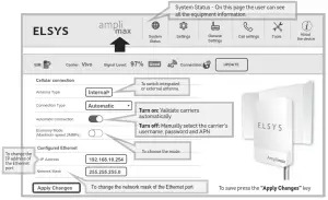
* If the automatic option does not work, make sure that the equipment is receiving some signal from the carrier.
FEATURED FEATURES:
BLIND SEARCH:
In the menu Tools is it is possible to do a BLIND SEARCH of carriers, even with a Sim Card installed in the product. Find out which carrier is performing best in your region.
BALANCE CONSULTATION:
Still on the menu Tools it is possible to receive and send SMS. This tool is useful to check messages sent by the carrier and to make data inquiries.
Another tool that allows you to make balance inquiries is the “USSD”, which is also in the menu Tools.
DATA COLLECTION
In the menu About the Device it is possible to enable or disable data collection, as well as to know its details.
EXTERNAL ANTENNA
Although this product is integrated with a high-performance Heptaband antenna, it allows the installation of an external antenna in a practical way in a TNC
connector, but there is an important detail about the cable length.
To avoid signal loss, the external antenna installation cable must not exceed 5ft.
WEB SETTING PAGE
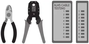
Required tools
1 cutting pliers
1 RJ-45 connector crimping pliers
1 network cable testing
Material needed:
2 high quality RJ-45 connectors
High quality RJ-45 network cable. At a minimum, it must be category 5e (cat. 5e)
Assembly Instructions
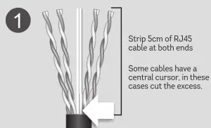
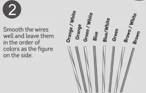
PREPARING THE RJ45 CABLE
Use RJ-45 cable category 5e approved by Anatel
 CHECK THE CABLE ALIGNMENT ON THE CONNECTOR
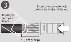
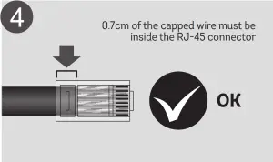
CRIMPING
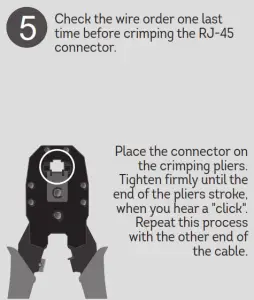
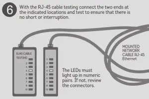
TEST THE CABLE
FACTORY RESET
To reset the equipment to the factory default, you can use the WEB setting page or the “EASY INSTALL” key on the product panel. With the product turned on, go to the Setting Page: General Settings / Factory Setting / Reset or hold the “EASY INSTALL” key for 7 seconds. A third way of restoring a factory default is to dial the number: # 1111 #, from the phone. Wait 90 seconds and the equipment will return to the factory settings.
GENERAL NOTES
- Use only original AC / DC adapter. Incompatible accessories compromise the operation, safety and warranty of the product.
- The AMPLIMAX power source must operate at 100 ~ 240VAC. Check the local voltage before connecting the device.
- If you want to clean, turn off the power and use only a slightly damp cloth. Do not use cleaning products, removers or aerosols.
- In order to ensure its best performance, do not install AMPLIMAX in locations with obstructions in the alignment sight with the chosen tower.
- Do not cover or place objects on AMPLIMAX.
- Do not use excessive force on the plastic parts.
- To prevent damage and loss of warranty, use the accessories supplied with the device.
- AMPLIMAX is compatible with 12VDC batteries and solar panels. (Observe the technical specifications in this manual).
- Avoid shock or impact. Improper handling can damage the external structure as well as the device’s internal circuits.
- During strong storms, it is advisable to disconnect the drop cable from the AMPLIMAX and the power source in the POE.
- Do not connect multiple power cables to a single outlet.
- Do not touch the plug with wet hands. Always hold and pull the plug and never the cable.
- Do not place heavy objects on the power cable or bend it excessively.
- Do not try to repair the device if it is not working. Any repairs must be carried out by qualified personnel.
- The power supply must be installed in properly ventilated, dry places and away from: objects with high temperatures, places with direct exposure to the sun, sources of water, fire or flammable / explosive materials.
WARRANTY AND TECHNICAL ASSISTANCE
SCOPE AND GUARANTEE TERM:
- This product is guaranteed by ELSYS for a period of one (1) year, including the three (3) months established by law. The term of this guarantee will be counted from the date of purchase of the product, evidenced by the purchase receipt of the product.
- In case of manufacturing defect within the guarantee period, the consumer must contact the seller. Analyzes and repairs, within the guarantee period, can only be carried out by ELSYS or by authorized companies. THIS PRODUCT GUARANTEE IS EXCLUDED:
1) With defects / damage resulting from failure to follow the installation and care instructions in the manual, as well as those caused by unforeseeable circumstances (floods, lightning, outbreaks, etc.) and accidents (falls, crashes, etc.).
2) With defects resulting from: use not in accordance with the recommended, improper installation, connections to the wrong voltage or with energy variation above that specified by the product.
3) Damaged packaging and product finish.
4) With altered, tampered or violated seals and / or serial numbers.
5) With sales invoice missing, showing erasures, modifications or any irregularities.
6) With the original power supply, supplied by ELSYS, replaced by any other one of a different or generic brand.
7) Shipped for repair without the power supply.
DATA COLLECTION
To monitor performance and improve the product, some data may be collected.
INFORMATION THAT WILL BE COLLECTED:
- Date / time: date and time of collection
- Serial number: Serial number “ELSYS” – Production control;
- IMEI: International Mobile Equipment Identification (Global Registration).
- MAC: Media Access Control (“Physical” address of the network interface).
- Software version: • Software version of the equipment.
- Modem Software Version: • Software version of the equipment modem.
- Antenna selection: Type of antenna being used (Internal or External).
- Carrier: User carrier (mcc / mnc).
- Connection technology (3G and G): Connection being used – 3G and / or 4G.
- Signal level: Signal level in dBm
- Signal Quality: Quality of the received signal in dB
- Network frequency: Frequency used by Amplimax.
- Lac: Area location code
- CelllD: Base station identification
- Power over Ethernet voltage – POE:
- Product Supply Voltage
- Module temperature: RF module temperature
- Phone Usage: Informs if the voice service was used
- Scheduled Reset: Informs if the programmed reset is enabled
- IPV6: Tells whether IPV6 is enabled
- Connection Status: Informs if the equipment had an active connection at the time of collection
- Antenna: Reports whether you are using an internal or external antenna
- IP WAN: Wan interface IP
- GPS Position: GPS position with error up to 164ftm.
- Upload and Download connection speed: Upload and Download data rate.
- Time of greatest movement of use: Time of greatest use (User profile).
- Average connection speed: Average data rate speed.
- Quantity of data consumed in the month: Data consumption in the month.
DATA COLLECTION
INFORMATION USE:
All information collected will be for the exclusive use of ELSYS Equipamentos Eletrônicos Ltda. Such information will be used by our team to monitor performance and to improve the development and offer of new products and services.
The sending of this information will occur automatically and can be disabled at any time by the user. To cancel, follow the detailed instructions below.
HOW TO DISABLE DATA COLLECTION:
To disable it, it is necessary to access the product setting web page.
Open the browser of your choice and enter the IP address of the AMPLIMAX (the factory default is 192.168.10.254). If all connections are correct, the product setting page can be accessed.
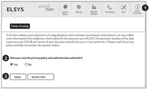
IN THE TOP MENU, PERFORM THE FOLLOWING STEPS:
- Choose the option:
- Answer the question about authorization for data collection.
- Select “Apply”.
*PLEASE NOTE:
- In regions where one carrier rents the signal (tower) from another, the blind search will only show the name of the carrier that owns the cellular network.
- Download / Upload rates and performance depend on the quality and availability of each carrier’s signal.
ELSYS disclaims any guarantee of upload and / or download rate, as these conditions are relevant to each
carrier. The peak download speed of 70Mbps depends on the rate of each carrier. - The range of this product (200x + signal and 5x + range) depends on the conditions of the installation, the relief of the region, the frequency of operation of the tower, among other factors.
- The external RJ-45 cable can reach 328ft without signal loss. This cable is not included.
- Remote monitoring of cameras and alarms depends on the carrier, the contracted plan (pre or post) and the resources available on the cameras or DVRs.
- To access the Internet it is necessary to acquire SIM Card (nano) with data plan enabled. The SIM card is not included.
Tested carriers: AT&T, TMobile.
FCC STATEMENT
This equipment has been tested and found to comply with the limits for a Class A digital device, pursuant to part 15 of the FCC Rules. These limits are designed to provide reasonable protection against harmful interference when the equipment is operated in a commercial environment. This equipment generates, uses, and can radiate radio frequency energy and, if not installed and used in accordance with the instruction manual, may cause harmful interference to radio communications. Operation of this equipment in a residential area is likely to cause harmful interference in which case the user will be required to correct the interference at his own expense.
The antenna(s) used for this transmitter must be installed to provide a separation distance of at least 20 cm from all persons. Changes or modifications not expressly approved by the party responsible for compliance could void the user’s authority to operate the equipment.
PACKAGING CONTENT
1 AMPLIMAX equipment;
1 Metal reflector;
1 DC – 24 V source;
1 1.4m network cable (Ethernet);
1 POE (Power Over Ethernet) injector;
2 Nylon cable ties with UV protection for fastening;
1 Nylon cable tie with UV protection for fastening;
2 Strips of self-fusing tape.
Weight / measure (Individual package): 3 lb / 14.4 x 3.6 x 8.6in
ASSEMBLY TEMPLATE

FASTENING THE PRODUCT ON A WALL
Ideal screw for wall mounting: ISO1478 screw
(DIN7970) – N10 (3/16” body and 3/8” head) pan head screw (Philips or slit)
S6, S7 or S8 bushing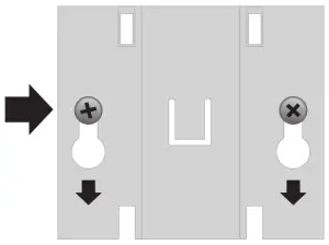
PRODUCT FASTENING ON THE MAST
AMPLIMAX Lite can be fixed to both mast and wall.
To attach to a mast, first wrap the two pieces of the self-fusing tape on the mast.
The spacing between the two pieces of tape should be around 2.6”, measured from center to center.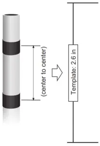
Manufactured by:![]() Brazilian industry
Brazilian industry
www.elsys.com
Made in Brazil.