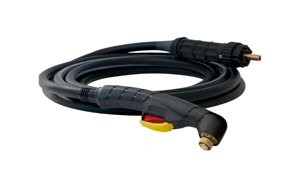
MT-70 Arc Welding Battery Chargers and Body Cable
FR 2-8 / 58-60 EN 9-15 / 58-60 DE 16-22 / 58-60 ES 23-29 / 58-60 RU 30-36 / 58-60 NL 37-43 / 58-60 IT 44-50 / 58-60 PL 51-57 / 58-60
V6_09/02/2023
MT-70 MT-125 EASYFIT
AT-70 AT-125 AT-160
www.gys.fr
MT / EASYFIT / AT
FR
AVERTISSEMENTS – RÈGLES DE SÉCURITÉ
CONSIGNE GÉNÉRALE
Ces instructions doivent être lues et bien comprises avant toute opération. Toute modification ou maintenance non indiquée dans le manuel ne doit pas être entreprise.
Tout dommage corporel ou matériel dû à une utilisation non-conforme aux instructions de ce manuel ne pourra être retenu à la charge du fabricant. En cas de problème ou d’incertitude, veuillez consulter une personne qualifiée pour manier correctement l’installation.
PROTECTION INDIVIDUELLE ET DES AUTRES
Le coupage peut être dangereux et causer des blessures graves voire mortelles. Le coupage expose les individus à une source dangereuse de chaleur, de rayonnement lumineux de l’arc, de champs électromagnétiques (attention au porteur de pacemaker), de risque d’électrocution, de bruit et d’émanations gazeuses. Pour bien se protéger et protéger les autres, respecter les instructions de sécurité suivantes :
Afin de se protéger de brûlures et rayonnements, porter des vêtements sans revers, isolants, secs, ignifugés et en bon état, qui couvrent l’ensemble du corps.
Utiliser des gants qui garantissent l’isolation électrique et thermique.
Utiliser une protection de coupage et/ou une cagoule de coupage d’un niveau de protection suffisant (variable selon les applications). Protéger les yeux lors des opérations de nettoyage. Les lentilles de contact sont particulièrement proscrites.
Il est parfois nécessaire de délimiter les zones par des rideaux ignifugés pour protéger la zone de coupage des rayons de l’arc, des projections et des déchets incandescents. Informer les personnes dans la zone de coupage de ne pas fixer les rayons de l’arc ni les pièces en fusion et de porter les vêtements adéquats pour se protéger.
Utiliser un casque contre le bruit si le procédé de coupage atteint un niveau de bruit supérieur à la limite autorisée (de même pour toute personne étant dans la zone de coupage).
Tenir à distance des parties mobiles (ventilateur) les mains, cheveux, vêtements. Ne jamais enlever les protections carter du groupe froid lorsque la source de courant de coupage est sous tension, le fabricant ne pourrait être tenu pour responsable en cas d’accident. Les pièces qui viennent d’être coupées sont chaudes et peuvent provoquer des brûlures lors de leur manipulation. Lors d’intervention d’entretien sur la torche, il faut s’assurer que celle-ci soit suffisamment froide en attendant au moins 10 minutes avant toute intervention. Le groupe froid doit être allumé lors de l’utilisation d’une torche refroidie eau afin d’être sûr que le liquide ne puisse pas causer de brûlures. Il est important de sécuriser la zone de travail avant de la quitter afin de protéger les personnes et les biens.
FUMÉES DE COUPAGE ET GAZ
Les fumées, gaz et poussières émis par le coupage sont dangereux pour la santé. Il faut prévoir une ventilation suffisante et un apport d’air est parfois nécessaire. Un masque à air frais peut être une solution en cas d’aération insuffisante. Vérifier que l’aspiration est efficace en la contrôlant par rapport aux normes de sécurité.
Attention, le coupage dans des milieux de petites dimensions nécessite une surveillance à distance de sécurité. Par ailleurs le coupage de certains matériaux contenant du plomb, cadmium, zinc ou mercure voire du béryllium peuvent être particulièrement nocifs, dégraisser également les pièces avant de les couper. Les bouteilles doivent être entreposées dans des locaux ouverts ou bien aérés. Elles doivent être en position verticale et maintenues à un support ou sur un chariot. Le coupage doit être proscrit à proximité de graisse ou de peinture.
RISQUE DE FEU ET D’EXPLOSION
Protéger entièrement la zone de coupage, les matières inflammables doivent être éloignées d’au moins 11 mètres. Un équipement anti-feu doit être présent à proximité des opérations de coupage.
Attention aux projections de matières chaudes ou d’étincelles et même à travers des fissures, elles peuvent être source d’incendie ou d’explosion. Éloigner les personnes, les objets inflammables et les containers sous pressions à une distance de sécurité suffisante. Le coupage dans des containers ou des tubes fermés est à proscrire et dans le cas où ils sont ouverts il faut les vider de toute matière inflammable ou explosive (huile, carburant, résidus de gaz …). Les opérations de meulage ne doivent pas être dirigées vers la source de courant de coupage ou vers des matières inflammables.
2
MT / EASYFIT / AT
FR
SÉCURITÉ ÉLECTRIQUE
Une décharge électrique peut être une source d’accident grave direct ou indirect, voire mortel.
Ne jamais toucher les parties sous tension de la torche car celle-ci est branchée au circuit de coupage. Ne pas toucher en même temps la torche et la pince de masse. Toujours utiliser des vêtements secs et en bon état pour s’isoler du circuit de coupage. Portez des chaussures isolantes, quel que soit le milieu où vous travaillez.
PRÉCAUTION D’EMPLOI
N’enroulez jamais la torche autour de votre corps. Ne pas utiliser la torche pour déplacer la source de courant de coupage. La torche doit être totalement déroulée afin d’éviter toute surchauffe. Arrêtez le générateur de courant après que la torche soit refroidie et avant chaque entretien et avant de remplacer ou contrôler les pièces d’usure. Contrôlez régulièrement l’état de la torche. Si celle-ci est endommagée, elle doit être remplacée.
DESCRIPTION GÉNÉRALE
SPÉCIFICATIONS
Les torches MT et EASYFIT sont destinées au procédé de coupage PLASMA manuel. Les torches AT sont destinées au procédé de coupage PLASMA automatisé.
DONNÉES TECHNIQUES
MT
Désignation
Angle de la torche
Longueur faisceau
Référence
Tension d’amorçage
Courant max assigné
Facteur de marche à 40°C
100 % 60 % 50 %
Type de gaz
Refroidissement de la torche
Plage de température ambiante en coupage
Plage de température ambiante de transport ou stockage
Caractéristique du switch (gâchette)
Norme appliquée
CUTTER 45 CT
MT-70 75°
6 m 12 m 037502 037519
500 V max 125 A 50 A 65 A 70 A air air
-10 -> +40°C
-10 -> +55°C
0.5 A / 48 V DC
EN IEC 60974-7
MT-125
75°
6 m
12 m
039506 039513
500 V max
125 A
100 A
125 A
–
air
air
-10 -> +40°C
-10 -> +55°C
0.5 A / 48 V DC EN IEC 60974-7
Compatibilité produit
CUTTER 70 CT NEOCUT 105
NEOCUT 125
3
MT / EASYFIT / AT
FR
EASYFIT
Désignation
Angle de la torche
Longueur faisceau
Référence
Tension d’amorçage
Courant max assigné
Facteur de marche à 40°C
100 % 60 % 50 %
Type de gaz
Refroidissement de la torche
Plage de température ambiante en coupage
Plage de température ambiante de transport ou stockage
Caractéristique du switch (gâchette)
Norme appliquée
CUTTER 45 CT
Faisceau poignée
–
6 m
12 m
074668 074675
500 V max
125 A
105 A
125 A
–
air
air
-10 -> +40°C
-10 -> +55°C
EN IEC 60974-7
Compatibilité produit
CUTTER 70 CT NEOCUT 105
NEOCUT 125
EASYFIT MT-70
EASYFIT MT-125
75°
15°
75°
15°
–
074583 074590 074606 074613
500 V max
125 A
50 A
65 A
70 A
air
air
Rallonge EASYFIT MT-125
90°
15°
90°
15°
80 cm
130 cm
074620 074637 074644 074651
500 V max
125 A
105 A
125 A
–
air
air
-10 -> +40°C
-10 -> +40°C
-10 -> +55°C
-10 -> +55°C
0.5 A / 48 V DC EN IEC 60974-7
0.5 A / 48 V DC EN IEC 60974-7
AT
Désignation
Longueur corps de torche
Diamètre corps de torche
Longueur faisceau
Référence
Tension d’amorçage
Courant max assigné
Facteur de marche à 40°C
100 % 60 % 50 %
Type de gaz
Refroidissement de la torche
Plage de température ambiante en coupage
Plage de température ambiante de transport ou stockage
Norme appliquée
CUTTER 45 CT
AT-70
127 mm
240 mm
Ø 35 mm
6 m
6 m
12 m
071865 037526 037533
500 V max
125 A
50 A
65 A
70 A
air
air
-10 -> +40°C
-10 -> +55°C EN IEC 60974-7
6 m 038479
AT-125 240 mm Ø 35 mm 12 m 15 m 039520 069787 500 V max
125 A 100 A 125 A
air air
-10 -> +40°C
-10 -> +55°C
EN IEC 60974-7
20 m 069794
6 m 067479
AT-160 240 mm Ø 44.5 mm 12 m 15 m 067486 069800 500 V max
125 A 125 A
air air
-10 -> +40°C
-10 -> +55°C
EN IEC 60974-7
20 m 069817
Compatibilité produit
CUTTER 70 CT NEOCUT 105
NEOCUT 125
4
MT / EASYFIT / AT
FR
PRESSION / DÉBIT RECOMMANDÉ
MT
COUPAGE
Courant
MT-70 6 m
MT-70 12 m
20 > 70 A
5.0 bar – 185 l/min COUPAGE
5.6 bar – 185 l/min
Courant
MT-125 6 m
MT-125 12 m
Precision cut 45 A 45 A 65 A 85 A 105 A 125 A
5.0 bar – 220 l/min 5.0 bar 215 l/min 5.0 bar 220 l/min 5.0 bar 250 l/min 5.0 bar 285 l/min 5.5 bar 305 l/min
5.6 bar – 220 l/min 5.6 bar 215 l/min 5.6 bar 220 l/min 5.6 bar 250 l/min 5.6 bar 285 l/min 6.2 bar 305 l/min
Courant 70 A
Courant 85 > 125 A
GOUGEAGE
MT-70 6 m
5.0 bar – 185 l/min GOUGEAGE
MT-125 6 m
4.0 bar
MT-70 12 m 5.6 bar – 185 l/min
MT-125 12 m 4.5 bar
AT
COUPAGE
Courant
AT-70 6 m
20 > 70 A
5.0 bar – 185 l/min
Courant
Precision cut 45 A 45 A 65 A 85 A 105 A 125 A
COUPAGE AT-125
6 m 5.0 bar – 220 l/min 5.0 bar 215 l/min 5.0 bar 220 l/min 5.0 bar 250 l/min 5.0 bar 285 l/min 5.5 bar 305 l/min
Courant
45 A 65 A 85 A 105 A 125 A
COUPAGE AT-160
6 m 5.0 bar 275 l/min 5.0 bar 285 l/min 5.0 bar 300 l/min 5.0 bar 355 l/min 5.0 bar 355 l/min
AT-70 12 m
5.6 bar – 185 l/min
AT-125 12 m 5.6 bar – 220 l/min 5.6 bar 215 l/min 5.6 bar 220 l/min 5.6 bar 250 l/min 5.6 bar 285 l/min 6.2 bar 305 l/min
AT-160 12 m 5.3 bar 275 l/min 5.4 bar 285 l/min 5.6 bar 300 l/min 6.0 bar 355 l/min 6.0 bar 355 l/min
Courant 20 > 70 A
EASYFIT
COUPAGE
Faisceau 6 m +
EASYFIT MT-70 5.0 bar – 185 l/min
Courant
Precision cut 45 A 45 A 65 A 85 A 105 A 125 A
COUPAGE
Faisceau 6 m +
EASYFIT MT-125 5.0 bar – 220 l/min 5.0 bar 215 l/min 5.0 bar 220 l/min 5.0 bar 250 l/min 5.0 bar 285 l/min 5.5 bar 305 l/min
Faisceau 12 m +
EASYFIT MT-70 5.6 bar – 185 l/min
Faisceau 12 m +
EASYFIT MT-125 5.6 bar – 220 l/min 5.6 bar 215 l/min 5.6 bar 220 l/min 5.6 bar 250 l/min 5.6 bar 285 l/min 6.2 bar 305 l/min
Courant 70 A
Courant 85 > 125 A
GOUGEAGE
Faisceau 6 m +
EASYFIT MT-70 5.0 bar – 185 l/min
GOUGEAGE
Faisceau 6 m +
EASYFIT MT-125 4.0 bar
Faisceau 12 m +
EASYFIT MT-70 5.6 bar – 185 l/min
Faisceau 12 m +
EASYFIT MT-125 4.5 bar
5
MT / EASYFIT / AT
FR
INSTALLATION
EXIGENCE DE RACCORDEMENT DE LA TORCHE
Le générateur doit être mis hors tension.
A
1*
B
Pour assembler le faisceau poignée avec une torche EASYFIT, insérer le connecteur de la torche (A) dans le logement femelle du faisceau et visser la partie B. Bien serrer la torche.
BA
Connection de la torche au générateur :
2
Insérer le connecteur du faisceau poignée (A) dans le logement femelle du faisceau (C) du générateur et visser la partie B. Bien
serrer la torche.
C
*L’étape 1 concerne seulement les torches EASYFIT.
ÉQUIPEMENT DES TORCHES
La torche doit être équipée avec les bons consommables, choisis en fonction de l’application et du courant réglé. Un mauvais choix de consommable provoquera des défauts de coupage, l’usure prématurée des consommables et voire un dysfonctionnement de l’ensemble. La torche est livrée avec un pot de graisse silicone afin de limiter l’usure du joint et le grippage des parties métalliques. Il est conseillé d’appliquer cette graisse régulièrement.
Consommables Vérifier régulièrement l’état d’usure de la buse de protection, de la tuyère et de l’électrode ou en cas de réduction significative de la vitesse de découpage. Il est conseillé de remplacer en même temps la tuyère et l’électrode.
MT & EASYFIT
Modèle de torche
MT-70 Coupage
MT-125
Calibre
Diffuseur (x1)
20-50 A 70 A
037557
Precision cut 45 A
45 A
65 A 85 A 105 A 125 A
039131 039131 039148
Électrode (x5) 037564 courte 067189 longue 037564 courte 067189 longue
039155
039155
MT-70 Gougeage
MT-125
Calibre
70 A 65-85 A 105 A 125 A
Diffuseur (x1) 037557 039131
039148
Électrode (x5) 037564
039155
Tuyère (x5) 037571 courte 067196 longue 037588 courte 067202 longue
039315
039162 039179 039186 039193 039209
Buse (x1) 037601 039216 039216 039223
Patin (x1) 037625 courte 067219 longue 037625 courte 067219 longue
039322
039230
039247
Tuyère (x5) 037595 039261 039278 039285
Buse (x1) 037601 039216
039223
Patin (x1) 037632
039254
6
MT / EASYFIT / AT
FR
Consommables «Accès difficile»
Modèle de torche
MT-70 Coupage
MT-125
MT-70 Gougeage
MT-125
Calibre 20-45 A
70 A 20-45 A
70 A 100 A 70 A 70 A 100 A
Diffuseur (x1) Électrode (x3)
037557
074682
039131
039148 037557 039131 039148
074699 074682 074699
Buse (x1) 074859
074866 074859 074866
Bague (x3) 074897
074897 074897 074897
Tuyère (x5) 074767 074774 074767 074774 074781
074798
074798 074804
Patin (x1) 074910
074910 074927 074927
ab
76 mm 122 mm
82 mm 131 mm
76 mm 122 mm 82 mm 131 mm
Consommables «Flat cutting»
Modèle de torche MT-70
Coupage MT-125
Calibre 40-70 A 40-70 A 80-125 A
Diffuseur (x1) 074736 074743 074750
Électrode (x5) 074705 074712 039155
Buse (x1) 074873
074880
Tuyère (x5) 074811 074828 074835
Bague de maintien (x2) 074903
AT
Modèle de torche AT-70 Coupage AT-125 Coupage
AT-160 Coupage
Calibre
20-50 A 70 A
Precision cut 45 A
45 A 65 A 85 A 105 A 125 A Precision cut 45 A 45 A 65 A 85 A 105-125
A 160 A
Diffuseur (x1) 037557 039131 039148
067509
Électrode (x5) 037564 039155
037493
Tuyère (x5)
037571 037588
039315
039162 039179 039186 039193 039209
037516
067523 067530 067547
067554
067561
Buse (x1)
Buse ohmique (x1)
037601 ou
037618
039216 ou
039339
Déflecteur auto (x1)
037649
037496
039292
039223 ou
039445
067578 –
039308 076945 067592
067585
067608
SOURCE DE DÉFAUT
CONSOMMABLES
BUSE GAZ
Les consommables sont des éléments d’usure, il est important de savoir à quels moments les changer. Visuellement : état des consommables fondu ou abîmé, trous de tuyères >1.5mm, électrodes usées, patins fondus… Pratiquement : perte de performance de coupage, amorçage sur pièce difficile, etc.
Serrer la buse de sorte que toutes les pièces soient bien bloquées. La tuyère ne doit pas tourner facilement.
Utiliser de l’air comprimé avec filtration de l’huile et de l’eau.
7
MT / EASYFIT / AT
FR
ANOMALIES, CAUSES, REMÈDES
SYMPTÔME Pas d’amorçage d’arc.
Interruption de l’arc de coupe.
CAUSES POSSIBLE
Torche mal connectée au générateur.
Pression d’air comprimée inappropriée.
Pièce consommable manquante (buse, tuyère, électrode, diffuseur). Défaut de montage des consommables.
Pince de masse mal connectée (Si interruption après quelques secondes de coupe). Vitesse d’avance de coupe inappropriée.
Distance entre la pièce à découper et la buse de la torche trop importante.
Coupure d’alimentation en air comprimée.
Consommable endommagé dans la torche.
Usure prématurée des consommables.
Pression d’air insuffisante. Vitesse d’avance de coupe trop rapide.
Présence d’impuretés ou d’humidité dans l’air comprimée.
Surface de la pièce à découper souillée. Vitesse d’avance de coupe trop rapide.
Excès de bavures sous la pièce après découpe.
Pression d’air comprimée inappropriée.
Valeur du courant de découpe trop faible par rapport à l’épaisseur de la pièce à découper.
Torche non maintenue perpendiculaire à la surface de la pièce à découper.
Saignée non perpendiculaire à la surface de la tôle.
Consommables mal montés dans la torche (buse non serrée…).
Valeur du courant de découpe trop faible par rapport à l’épaisseur de la pièce à découper.
REMÈDE Vérifier la connexion de la torche sur le générateur. Ajuster la pression de l’air à la valeur recommandée.
Remplacer les pièces manquantes.
L’électrode n’est pas en contact avec la tuyère. Vérifier que la pince de masse est bien connectée sur une surface décapée de la tôle à découper. Ajuster la vitesse de coupe.
Rapprocher la torche de la pièce.
Vérifier l’alimentation en air comprimée Inspecter les pièces consommables de la torche et procéder à leur remplacement. Ajuster la pression d’air. Ajuster la vitesse de coupe
Vérifier le filtre à air sur le générateur.
Nettoyer et décaper la surface de la tôle à découper. Ajuster la vitesse de coupe Ajuster la pression de l’air à la valeur recommandée Ajuster la valeur du courant de découpe sur le générateur.
Améliorer le maintien de la torche.
Réajuster le montage et le serrage des consommables.
Ajuster la valeur du courant de découpe sur le générateur.
CERTIFICATION ET CONSIGNE DE TRI
Matériel conforme aux directives européennes. La déclaration UE de conformité est disponible sur notre site (voir à la page de couverture).
Matériel conforme aux exigences britanniques. La déclaration de conformité britannique est disponible sur notre site (voir à la page de couverture).
Matériel conforme aux normes Marocaines. La déclaration C (CMIM) de conformité est disponible sur notre site (voir à la page de couverture).
Produit recyclable qui relève d’une consigne de tri.
Ce matériel fait l’objet d’une collecte sélective selon la directive européenne 2012/19/UE. Ne pas jeter dans une poubelle domestique !
CONDITIONS DE GARANTIE FRANCE
La garantie couvre tous défauts ou vices de fabrication pendant 2 ans, à compter de la date d’achat (pièces et main d’oeuvre). La garantie ne couvre pas : · Toutes autres avaries dues au transport. · L’usure normale des pièces (Ex. : câbles, pinces, etc.). · Les incidents dus à un mauvais usage (erreur d’alimentation, chute, démontage). · Les pannes liées à l’environnement (pollution, rouille, poussière).
En cas de panne, retourner l’appareil à votre distributeur, en y joignant : – un justificatif d’achat daté (ticket de sortie de caisse, facture….)
8 – une note explicative de la panne.
MT / EASYFIT / AT
EN
WARNINGS – SAFETY REGULATIONS
GENERAL INSTRUCTIONS
The instructions in this user manual must be read and understood before operating the machine. Do not undertake any modifications or maintenance work that is not included in the user manual.
The manufacturer shall not be liable for any damage to persons or property resulting from using the product in a manner not in accordance with the instructions in this user manual. If there are any problems or queries, please consult a qualified technician to properly set up the equipment.
PROTECTING YOURSELF AND OTHERS
Cutting metal can be dangerous and cause serious injury or death. Cutting metal exposes individuals to a dangerous heat source, light radiation from the arc, electromagnetic fields (attention those with pacemakers), risk of electrocution, noise and gas fumes. Follow the following safety guidelines to protect yourself and others:
Wear the appropriate clothing to protect yourself from burns and radiation: cuffless, insulated, dry, flame-retardant clothing in good condition that covers the whole body.
Wear gloves that ensure electrical and thermal insulation.
Use a protective welding and cutting curtain and/or a cutting hood with a sufficient protection level (varies according to the application). Protect your eyes during cleaning operations. Contact lenses are strictly prohibited.
It is sometimes necessary to delimit areas using fireproof curtains to protect the cutting area from arc rays, spatter and incandescent waste. Inform people in the cutting area not to look at the arc rays or the melted parts, also advise them to wear the appropriate clothing to protect themselves.
Use noise-cancelling headphones if the cutting process reaches a noise level above the permitted level (these headphones should be offered to anyone in the cutting area).
Keep hands, hair and clothes away from moving parts (fans). Never remove the protective casing from the cooling unit when the power source is switched on as the manufacturer cannot be held responsible in the event of an accident.
Freshly cut parts are hot and can cause burns if handled. When servicing the torch, ensure that it is cool enough by waiting for at least ten minutes before undertaking any maintenance work. The cooling unit must be switched on when using a water-cooled torch to ensure that the liquid does not cause burns. It is important to secure the work area before leaving it; this is to protect people and property.
CUTTING FUMES AND GASES
The fumes, gases and dusts emitted by cutting processes are hazardous to one’s health. Sufficient ventilation must be provided and an additional air supply may be necessary. An air-fed mask could be an appropriate solution if the ventilation is inadequate. Check that the suction is effective by checking it against safety standards.
Warning: cutting in confined spaces requires remote monitoring for safety. Furthermore, the cutting of certain materials that contain lead, cadmium, zinc, mercury or even beryllium, can be particularly harmful; it is important to degrease parts before cutting them. Gas cylinders should be stored in an open or well-ventilated area. They must be in an upright position and secured to a stand or trolley. Cutting applications should not be carried out near grease or paint.
FIRE AND EXPLOSION HAZARD
The cutting area must be fully protected; flammable materials should be kept at least 11 metres away. Fire-fighting equipment must be available in the vicinity of cutting operations.
Beware of hot substances or sparks being projected, even through cracks; these can cause a fire or explosion. Keep people, flammable objects and pressurised containers at a safe distance. Cutting in closed containers or tubes should be avoided; if they are open, they should be emptied of any flammable or explosive material (oil, fuel and gas residues, etc.).
9
MT / EASYFIT / AT
EN
Grinding operations must not be directed towards the cutting current’s source or any flammable materials.
ELECTRICAL SAFETY
Electric shocks can cause serious direct or indirect accidents and even death.
Never touch the torch’s live parts because it is connected to the cutting circuit. Do not touch the torch and the earth clamp at the same time. Always use dry and undamaged clothing to insulate yourself from the cutting circuit. Wear insulated footwear, regardless of your working environment.
CAUTION FOR USE
Never wrap the torch cables around your body. Do not use the torch to move the source of the cutting current. The torch must be completely unwound in order to avoid overheating. Switch off the power source after the torch has cooled down before any maintenance work and before replacing or checking worn parts. Regularly check the torch’s condition. It must be replaced if it becomes damaged.
GENERAL DESCRIPTION
SPECIFICATIONS
The MT and EASYFIT torches are designed for manual plasma cutting. AT torches are designed for automated plasma cutting.
TECHNICAL DATA
MT
Description
Torch angle
Cable-bundle length
Part Number
Ignition voltage
Max. rated current
100%
Duty cycle at 40°C
60%
50%
Gas type
Torch cooling
Ambient cutting temperature range
Ambient storage / transport temperature range
MT-70 75°
6 m 12 m 037502 037519
500 V max. 125 A 50 A 65 A 70 A air air
-10 -> +40°C
-10 -> +55°C
MT-125
75°
6 m
12 m
039506 039513
500 V max.
125 A
100 A
125 A
–
air
air
-10 -> +40°C
-10 -> +55°C
Switch characteristics (trigger)
Applied standard
0.5 A / 48 V DC EN IEC 60974-7
0.5 A / 48 V DC EN IEC 60974-7
CUTTER 45 CT
Product compatibility
CUTTER 70 CT NEOCUT 105
NEOCUT 125
10
MT / EASYFIT / AT
EN
EASYFIT
Description Torch angle
Cable-bundle length
Part Number
Ignition voltage
Max. rated current
100%
Duty cycle at 40°C
60%
50%
Gas type
Torch cooling
Ambient cutting temperature range
Ambient storage / transport temperature range
Switch characteristics (trigger)
Applied standard
CUTTER 45 CT
Handle bundle
–
6 m
12 m
074668 074675
500 V max.
125 A
105 A
125 A
–
air
air
-10 -> +40°C
-10 -> +55°C
EN IEC 60974-7
Product compatibility
CUTTER 70 CT NEOCUT 105
NEOCUT 125
EASYFIT MT-70
75°
15°
EASYFIT MT-125
75°
15°
–
074583 074590 074606 074613
500 V max.
125 A
50 A
65 A
70 A
air
air
EASYFIT MT-125 extension cable
90°
15°
90°
15°
80 cm
130 cm
074620 074637 074644 074651
500 V max.
125 A
105 A
125 A
–
air
air
-10 -> +40°C
-10 -> +40°C
-10 -> +55°C
-10 -> +55°C
0.5 A / 48 V DC EN IEC 60974-7
0.5 A / 48 V DC EN IEC 60974-7
AT
Description
Torch-body length
Torch-body diameter
Cable-bundle length
Part Number
Ignition voltage
Max. rated current
100%
Duty cycle at 40°C
60%
50%
Gas type
Torch cooling
Ambient cutting temperature range
Ambient storage / transport temperature range
Applied standard
AT-70
127 mm
240 mm
Ø 35 mm
6 m
6 m
12 m
071865 037526 037533
500 V max.
125 A
50 A
65 A
70 A
air
air
-10 -> +40°C
-10 -> +55°C EN IEC 60974-7
6 m 038479
AT-125 240 mm Ø 35 mm 12 m 15 m 039520 069787 500 V max.
125 A 100 A 125 A
air air
-10 -> +40°C
-10 -> +55°C
EN IEC 60974-7
20 m 069794
6 m 067479
AT-160 240 mm Ø 44.5 mm 12 m 15 m 067486 069800 500 V max.
125 A 125 A
air air
-10 -> +40°C
-10 -> +55°C
EN IEC 60974-7
20 m 069817
CUTTER 45 CT
Product compatibility
CUTTER 70 CT NEOCUT 105
NEOCUT 125
11
MT / EASYFIT / AT
EN
RECOMMENDED PRESSURE / FLOW
MT
CUTTING
Current
MT-70 6 m
MT-70 12 m
20 > 70 A
5.0 bar – 185 l/min CUTTING
5.6 bar – 185 l/min
Current
MT-125 6 m
MT-125 12 m
Precision cut 45 A 45 A 65 A 85 A 105 A 125 A
5.0 bar – 220 l/min 5.0 bar 215 l/min 5.0 bar 220 l/min 5.0 bar 250 l/min 5.0 bar 285 l/min 5.5 bar 305 l/min
5.6 bar – 220 l/min 5.6 bar 215 l/min 5.6 bar 220 l/min 5.6 bar 250 l/min 5.6 bar 285 l/min 6.2 bar 305 l/min
Current 70 A
Current 85 > 125 A
GOUGING
MT-70 6 m
5.0 bar – 185 l/min GOUGING
MT-125 6 m
4.0 bar
MT-70 12 m 5.6 bar – 185 l/min
MT-125 12 m 4.5 bar
AT
CUTTING
Current
AT-70 6 m
20 > 70 A
5.0 bar – 185 l/min
Current
Precision cut 45 A 45 A 65 A 85 A 105 A 125 A
CUTTING AT-125
6 m 5.0 bar – 220 l/min 5.0 bar 215 l/min 5.0 bar 220 l/min 5.0 bar 250 l/min 5.0 bar 285 l/min 5.5 bar 305 l/min
Current
45 A 65 A 85 A 105 A 125 A
CUTTING AT-160
6 m 5.0 bar 275 l/min 5.0 bar 285 l/min 5.0 bar 300 l/min 5.0 bar 355 l/min 5.0 bar 355 l/min
AT-70 12 m
5.6 bar – 185 l/min
AT-125 12 m 5.6 bar – 220 l/min 5.6 bar 215 l/min 5.6 bar 220 l/min 5.6 bar 250 l/min 5.6 bar 285 l/min 6.2 bar 305 l/min
AT-160 12 m 5.3 bar 275 l/min 5.4 bar 285 l/min 5.6 bar 300 l/min 6.0 bar 355 l/min 6.0 bar 355 l/min
12
Current 20 > 70 A
EASYFIT
CUTTING
Bundle (6 m) +
EASYFIT MT-70 5.0 bar – 185 l/min
Current
Precision cut 45 A 45 A 65 A 85 A 105 A 125 A
CUTTING
Bundle (6 m) +
EASYFIT MT-125 5.0 bar – 220 l/min 5.0 bar 215 l/min 5.0 bar 220 l/min 5.0 bar 250 l/min 5.0 bar 285 l/min 5.5 bar 305 l/min
Bundle (12 m) +
EASYFIT MT-70 5.6 bar – 185 l/min
Bundle (12 m) +
EASYFIT MT-125 5.6 bar – 220 l/min 5.6 bar 215 l/min 5.6 bar 220 l/min 5.6 bar 250 l/min 5.6 bar 285 l/min 6.2 bar 305 l/min
Current 70 A
Current 85 > 125 A
GOUGING
Bundle (6 m) +
EASYFIT MT-70 5.0 bar – 185 l/min
GOUGING
Bundle (6 m) +
EASYFIT MT-125 4.0 bar
Bundle (12 m) +
EASYFIT MT-70 5.6 bar – 185 l/min
Bundle (12 m) +
EASYFIT MT-125 4.5 bar
MT / EASYFIT / AT
EN
SETTING UP
TORCH CONNECTION REQUIREMENTS
The power source must be turned off.
A
1*
B
To assemble the handle bundle with an EASYFIT torch, insert the torch connector (A) into the bundle socket and screw on part B. Tighten the torch.
BA
Connecting the torch to the power source:
2
Insert the handle bundle connector (A) into the power source’s
female bundle socket (C) and screw on part B. Tighten the torch.
C
*Step 1 is only for EASYFIT torches.
TORCH EQUIPMENT
The torch must be fitted with the correct consumables, chosen according to the application and the set current. Choosing the incorrect consumable will result in cutting defects, premature wearing of the consumables and could even cause the entire unit to malfunction. The torch is supplied with a pot of silicone grease to minimise the seal’s wear and the seizing of metal parts. It is recommended to apply this grease regularly.
Consumables Regularly check the condition of the protective nozzle, the contact tip and the electrode for wear and tear, also check these parts if the cutting speed is significantly reduced. It is advisable to replace the nozzle’s contact tip and the electrode at the same time.
MT & EASYFIT
Torch model MT-70
Cutting MT-125
MT-70 Gouging
MT-125
Calibrate
Diffuser (x1)
20 – 50 A 70 A
037557
Precision cut 45 A
45 A
65 A 85 A 105 A 125 A
039131 039131 039148
Electrode (x5) 037564 short 067189 long 037564 short 067189 long
039155
039155
Calibrate
70 A 65 – 85 A
105 A 125 A
Diffuser (x1) 037557 039131
039148
Electrode (x5) 037564
039155
Contact tip (x5) 037571 short 067196 long 037588 short 067202 long
039315
039162 039179 039186 039193 039209
Nozzle (x1) 037601 039216
Pad (x1) 037625 short 067219 long 037625 short 067219 long
039322
039216
039230
039223
039247
Contact tip (x5) 037595 039261 039278 039285
Nozzle (x1) 037601 039216
039223
Pad (x1) 037632
039254
13
MT / EASYFIT / AT
EN
Difficult-access consumables
Torch model
MT-70 Cutting
MT-125
MT-70 Gouging
MT-125
Calibrate 20 – 45 A
70 A 20 – 45 A
70 A 100 A 70 A 70 A 100 A
Diffuser (x1) Electrode (x3)
037557
074682
039131
039148 037557 039131 039148
074699 074682 074699
Nozzle (x1) 074859
074866 074859 074866
Ring (x3) Contact tip (x5) Pad (x1)
074897 074897
074767
074774 074767 074774 074781
074910 074910
074897
074798
074927
074897
074798 074804
074927
ab
76 mm 122 mm
82 mm 131 mm
76 mm 122 mm 82 mm 131 mm
Flat-cutting consumables
Torch model MT-70
Cutting MT-125
Calibrate 40 – 70 A 40 – 70 A 80 – 125 A
Diffuser (x1) 074736 074743 074750
Electrode (x5) 074705 074712 039155
Nozzle (x1) 074873
074880
Contact tip (x5) 074811 074828 074835
Retaining ring (x2) 074903
AT
Torch model AT-70 Cutting AT-125 Cutting
AT-160 Cutting
Calibrate
20 – 50 A 70 A
Precision cut 45 A
45 A 65 A 85 A 105 A 125 A Precision cut 45 A 45 A 65 A 85 A 105 – 125
A 160 A
Diffuser (x1) 037557 039131 039148
067509
Electrode (x5) 037564 039155
037493
Contact tip (x5) Nozzle (x1)
037571 037588
037601 or
039315
039162 039179 039186 039193 039209
039216 or 039223 or
067516
067523
067530
067547
–
067554
067561
Ohmic nozzle (x1)
037618
Auto deflector (x1) 037649
039339
037496 039292
039445 067578
039308 076945 067592
067585
067608
DEFECT SOURCE
CONSUMABLES
NOZZLE GAS
Consumables are wearing parts, so it is important to know when to change them. Visually: melted or damaged consumables, holes in nozzles >1.5 mm, worn electrodes or melted pads, etc. Pragmatically: loss of cutting performance, ignition on difficult workpiece, etc. Tighten the nozzle so that all parts are securely fastened. The nozzle must not rotate easily.
Use compressed air with an oil and water filtration system.
14
MT / EASYFIT / AT
EN
ANOMALIES, CAUSES, SOLUTIONS
SYMPTOMS No arc ignition.
Interrupting the cutting arc.
The consumables are wearing prematurely. Excess burrs under the workpiece after cutting.
Not perpendicular to the metal sheet’s surface.
POSSIBLE CAUSES Torch incorrectly connected to the power source. Incorrect compressed-air pressure.
Missing consumable part (nozzle, contact tip electrode or diffuser, etc.). Consumables are not installed correctly.
Earth clamp not properly connected (if disconnected after a few seconds of cutting). Inappropriate cutting-feed speed. The distance between workpiece and torch’s nozzle is too great.
The compressed-air supply has been cut off. Damaged consumable in the torch.
Insufficient air pressure. The cutting-feed speed is too fast. Impurities or moisture in the compressed air.
Soiled cutting surface. The cutting-feed speed is too fast. Incorrect compressed-air pressure. The cutting current is too low for the thickness of the workpiece. Torch not held perpendicular to the surface of the workpiece.
Consumables incorrectly fitted in the torch (loose nozzle, etc.). The cutting current is too low for the thickness of the workpiece.
SOLUTIONS Check the torch’s conenction to the power source. Adjust the air pressure to the recommended value.
Replace missing parts.
The electrode is not in contact with the contact tip. Check that the earth clamp is connected to one of the sheet metal’s clean surfaces to be cut effectively. Adjust the cutting speed.
Bring the torch closer to the workpiece.
Check the compressed-air supply. Inspect the torch’s consumable parts and replace them. Adjust the air pressure. Adjust the cutting speed. Check the power source’s air filter. Clean and strip the surface of the sheet metal to be cut. Adjust the cutting speed. Adjust the air pressure to the recommended value.
Adjust the cutting current value on the power source.
Improving torch support.
Readjust the fitting and tightening of consumables.
Adjust the cutting current value on the power source.
CERTIFICATION AND SORTING GUIDELINES
This equipment in accordance with European directives. The EU Declaration of Conformity is available on our website (see the cover page).
This equipment complies with British standards. The UK declaration of conformity is available on our website (see the cover page).
This equipment complies with Moroccan standards. The C (CMIM) Declaration of Conformity is available on our website (see the cover page).
Recyclable product subject to specific waste-sorting requirements.
This equipment is subject to selective collection in accordance with European Directive 2012/19/EU. Do not dispose of this device in household waste.
FRENCH WARRANTY CONDITIONS
The warranty covers all defects or manufacturing faults for two years from the date of purchase (parts and labour). The warranty does not cover: · Any damage caused by transport. · The normal wear and tear of parts (e.g . cables and clamps, etc.). · Incidents caused by improper use (power supply errors, dropping or disassembling the device). · Environmental failures (pollution, rust and dust, etc.). In the event of a breakdown, return the device to your distributor including: – a dated proof of purchase (receipt or invoice) – a note explaining the breakdown.
15
MT / EASYFIT / AT
DE
WARNUNGEN – SICHERHEITSREGELN
ALLGEMEINER HINWEIS
Die Missachtung dieser Bedienungsanleitung kann zu schweren Personen- und Sachschäden führen. Nehmen Sie keine Wartungsarbeiten oder Veränderungen an dem Gerät vor, die nicht in der Anleitung genannt werden.
Der Hersteller haftet nicht für Verletzungen oder Schäden, die durch unsachgemäße Handhabung dieses Geräts entstanden sind. Bei Problemen oder Unsicherheiten wenden Sie sich bitte an eine Person, die für die ordnungsgemäße Durchführung der Installation qualifiziert ist.
PERSONENSCHUTZ
Das Schneiden kann gefährlich sein und zu schweren oder tödlichen Verletzungen führen. Beim Schneiden sind Personen einer gefährlichen Quelle von Hitze, Lichtbogenstrahlung, elektromagnetischen Feldern (Vorsicht bei Trägern von Herzschrittmachern), der Gefahr eines Stromschlags, Lärm und Gasen ausgesetzt. Schützen Sie daher sich selbst und andere. Beachten Sie unbedingt die folgenden Sicherheitshinweise:
Die Lichtbogenstrahlung kann zu schweren Augenschäden und Hautverbrennungen führen. Die Haut muss durch geeignete trockene Schutzbekleidung (Schweißhandschuhe, Lederschürze, Sicherheitsschuhe) geschützt werden.
Tragen Sie elektrisch- und wärmeisolierende Handschuhe.
Verwenden Sie einen Schneideschutz und/oder eine Schneideschutzmaske mit einem ausreichenden Schutzniveau (je nach Anwendung unterschiedlich). Schützen Sie Ihre Augen bei Reinigungsarbeiten. Kontaktlinsen sind ausdrücklich verboten!
Manchmal müssen die Bereiche mit feuerfesten Vorhängen abgegrenzt werden, um den Schneidbereich vor Lichtbogenstrahlen, Spritzern und glühenden Abfällen zu schützen. Informieren Sie die Personen im Schneidbereich, dass sie nicht in die Strahlen des Lichtbogens oder in geschmolzene Teile starren und zum Schutz geeignete Kleidung tragen sollen.
Verwenden Sie einen Lärmschutzhelm, wenn der Schneidprozess einen Lärmpegel erreicht, der über dem zulässigen Grenzwert liegt (das Gleiche gilt für alle Personen, die sich im Schneidbereich aufhalten).
Hände, Haare, Kleidung von den beweglichen Teilen (Ventilator) fernhalten. Entfernen Sie nie die Gehäuseabdeckungen des Kühlaggregats, wenn die Schaltstromquelle unter Spannung steht, da der Hersteller bei einem Unfall nicht haftbar gemacht werden kann.
Frisch geschnittene Teile sind heiß und können bei der Handhabung Verbrennungen verursachen. Bei Wartungsarbeiten am Brenner muss sichergestellt werden, dass er ausreichend abgekühlt ist, indem man mindestens 10 Minuten vor den Arbeiten wartet. Das Kühlaggregat muss bei der Verwendung eines wassergekühlten Brenners eingeschaltet sein, damit die Flüssigkeit keine Verbrennungen verursachen kann. Der Arbeitsbereich muss zum Schutz von Personen und Geräten vor dem Verlassen gesichert werden.
SCHNEIDDÄMPFE UND GASE
Die beim Schneiden entstehenden Dämpfe, Gase und Stäube sind gesundheitsgefährdend. Es muss für eine ausreichende Belüftung gesorgt werden, und manchmal ist eine Luftzufuhr erforderlich. Eine Frischluftmaske kann bei unzureichender Belüftung eine Lösung sein. Überprüfen Sie die Wirksamkeit der Luftansaugung, indem Sie diese anhand der Sicherheitsnormen überprüfen.
Achtung: Das Schneiden in kleinen Räumen erfordert eine sichere Fernüberwachung. Außerdem kann das Schneiden von bestimmten Materialien, die Blei, Cadmium, Zink oder Quecksilber und oder Beryllium enthalten, besonders schädlich sein. Vor dem Schneiden sollten Sie die Teile auch entfetten. Die Flaschen müssen in offenen oder gut belüfteten Räumen gelagert werden. Sie müssen sich in senkrechter Position befinden und an einer Halterung oder einem Fahrwagen angebracht sein. Das Schneiden in der Nähe von Fett oder Farbe ist strikt untersagt.
BRAND- UND EXPLOSIONSGEFAHR
Schirmen Sie den Schneidbereich vollständig ab, brennbare Materialien müssen mindestens 11 m entfernt sein. In der Nähe von Schneidvorgängen muss eine Brandschutzausrüstung vorhanden sein.
Beachten Sie, dass die beim Schweißen entstehende heiße Schlacke, Spritzer und Funken eine potentielle Quelle für Feuer oder Explosionen darstellen. Halten Sie einen Sicherheitsabstand zu Personen, entflammbaren Gegenständen und Druckbehältern ein. Das Schneiden in geschlossenen Containern oder Röhren ist zu vermeiden, und falls sie offen sind, dürfen sie keine brennbaren oder explosiven Materialien (Öl, Treibstoff, Gasrückstände …) enthalten. Schleifvorgänge dürfen nicht auf die Schneidstromquelle oder auf brennbare Materialien gerichtet werden.
16
MT / EASYFIT / AT
DE
ELEKTRISCHE SICHERHEIT
Das Berühren stromführender Teile kann tödliche elektrische Schläge und schwere Verbrennungen bis zum Tod verursachen.
Berühren Sie niemals die stromführenden Teile des Brenners, da dieser an den Schneidestromkreis angeschlossen ist. Berühren Sie nicht gleichzeitig den Brenner und die Masseklemme. Tragen Sie zur Isolierung beim Schweißen immer trockene Kleidung in gutem Zustand, um selbst vom Schneidestromkreis getrennt zu sein. Tragen Sie isoliertes Schuhwerk, unabhängig von der Umgebung, in der Sie arbeiten.
VORSICHTSMASSNAHME BEI DER VERWENDUNG
Wickeln Sie den Brenner nie um Ihren Körper. Verwenden Sie den Brenner nicht, um die Schneidstromquelle zu bewegen. Der Brenner muss vollständig abgerollt sein, um eine Überhitzung zu vermeiden. Schalten Sie die Stromquelle aus, nachdem der Brenner abgekühlt ist, und vor jeder Wartung und vor dem Austausch oder der Kontrolle von Verschleißteilen. Überprüfen Sie regelmäßig den Zustand des Brenners. Bei Beschädigung muss er ersetzt werden.
ALLGEMEINE BESCHREIBUNG
SPEZIFIKATIONEN
Die MT- und EASYFIT-Brenner sind für das manuelle PLASMA-Schneidverfahren bestimmt. Die AT-Brenner sind für das automatisierte PLASMA-Schneidverfahren bestimmt.
TECHNISCHE DATEN
MT
Bezeichnung
Winkel des Brenners
Länge des Schlachpakets Artikel-Nr.
Zündspannung Max. Bemessungsstrom
100 %
Einschaltdauer bei 40 °C
60 %
50 %
Art des Gases
Kühlung des Brenners Umgebungstemperaturbereich beim Schneiden
Umgebungstemperaturbereich für Transport oder Lagerung
Schaltermerkmal (Drucktaster) Angewandte Norm
MT-70 75°
6 m 12 m 037502 037519
500 V max 125 A 50 A 65 A 70 A Luft Luft
-10 -> +40°C
-10 -> +55°C
0.5 A / 48 V DC EN IEC 60974-7
MT-125
75°
6 m
12 m
039506 039513
500 V max
125 A
100 A
125 A
–
Luft
Luft
-10 -> +40°C
-10 -> +55°C
0.5 A / 48 V DC EN IEC 60974-7
CUTTER 45 CT
Produktkompatibilität
CUTTER 70 CT NEOCUT 105
NEOCUT 125
17
MT / EASYFIT / AT
DE
EASYFIT
Bezeichnung Winkel des Brenners
Länge des Kabelbaums Artikel-Nr.
Zündspannung Max. Bemessungsstrom
Einschaltdauer bei 40 °C
Art des Gases
100 % 60 % 50 %
Abkühlung des Brenners Umgebungstemperaturbereich beim Schneiden Umgebungstemperaturbereich für Transport oder Lagerung
Schaltermerkmal (Drucktaster) Angewandte Norm
CUTTER 45 CT
Brennergriff –
6 m
12 m
074668 074675 500 V max 125 A 105 A 125 A Luft Luft
-10 -> +40°C
-10 -> +55°C
EN IEC 60974-7
Produktkompatibilität
CUTTER 70 CT NEOCUT 105
NEOCUT 125
EASYFIT MT-70
75°
15°
EASYFIT MT-125
75°
15°
Verlängerungskabel EASYFIT MT-125
90°
15°
90°
15°
–
80 cm
130 cm
074583 074590 500 V max 125 A 50 A 65 A 70 A Luft Luft
074606
074613
074620 074637 500 V max 125 A 105 A 125 A Luft Luft
074644
074651
-10 -> +40°C
-10 -> +40°C
-10 -> +55°C
0.5 A / 48 V DC EN IEC 60974-7
-10 -> +55°C
0.5 A / 48 V DC EN IEC 60974-7
AT
Bezeichnung
Länge des Brennergriffs Durchmesser des Brennergriffs Länge des Schlauchpakets
Artikel-Nr.
Zündspannung Max. Bemessungsstrom
Einschaltdauer bei 40 °C
100 % 60 % 50 %
Art des Gases
Abkühlung des Brenners
Umgebungstemperaturbereich beim Schneiden
Umgebungstemperaturbereich für Transport oder Lagerung
Angewandte Norm
AT-70
127 mm
240 mm
Ø 35 mm
6 m
6 m
12 m
071865 037526 037533 500 V max 125 A 50 A 65 A 70 A Luft Luft
-10 -> +40°C
-10 -> +55°C EN IEC 60974-7
6 m 038479
AT-125 240 mm Ø 35 mm
12 m 15 m
039520 069787 500 V max 125 A 100 A 125 A Luft Luft
-10 -> +40°C
-10 -> +55°C
EN IEC 60974-7
20 m 069794
6 m 067479
AT-160 240 mm Ø 44.5 mm
12 m 15 m
067486 069800 500 V max 125 A 125 A Luft Luft
-10 -> +40°C
-10 -> +55°C
EN IEC 60974-7
20 m 069817
CUTTER 45 CT
Produktkompatibilität
CUTTER 70 CT NEOCUT 105
NEOCUT 125
18
MT / EASYFIT / AT
DE
EMPFOHLENER DRUCK / DURCHSATZ
MT
SCHNITT
Strom
MT-70 6 m
MT-70 12 m
20 > 70 A
5.0 bar – 185 l/min SCHNITT
5.6 bar – 185 l/min
Strom
MT-125 6 m
MT-125 12 m
Precision cut 45 A 45 A 65 A 85 A 105 A 125 A
5.0 bar – 220 l/min 5.0 bar 215 l/min 5.0 bar 220 l/min 5.0 bar 250 l/min 5.0 bar 285 l/min 5.5 bar 305 l/min
5.6 bar – 220 l/min 5.6 bar 215 l/min 5.6 bar 220 l/min 5.6 bar 250 l/min 5.6 bar 285 l/min 6.2 bar 305 l/min
Strom 70 A
Strom 85 > 125 A
FUGENHOBELN
MT-70 6 m
MT-70 12 m
5.0 bar – 185 l/min FUGENHOBELN
5.6 bar – 185 l/min
MT-125 6 m
MT-125 12 m
4.0 bar
4.5 bar
AT
SCHNITT
Strom
AT-70 6 m
20 > 70 A
5.0 bar – 185 l/min
Strom
Precision cut 45 A 45 A 65 A 85 A 105 A 125 A
SCHNITT AT-125
6 m 5.0 bar – 220 l/min 5.0 bar 215 l/min 5.0 bar 220 l/min 5.0 bar 250 l/min 5.0 bar 285 l/min 5.5 bar 305 l/min
Strom
45 A 65 A 85 A 105 A 125 A
SCHNITT AT-160
6 m 5.0 bar 275 l/min 5.0 bar 285 l/min 5.0 bar 300 l/min 5.0 bar 355 l/min 5.0 bar 355 l/min
AT-70 12 m
5.6 bar – 185 l/min
AT-125 12 m 5.6 bar – 220 l/min 5.6 bar 215 l/min 5.6 bar 220 l/min 5.6 bar 250 l/min 5.6 bar 285 l/min 6.2 bar 305 l/min
AT-160 12 m 5.3 bar 275 l/min 5.4 bar 285 l/min 5.6 bar 300 l/min 6.0 bar 355 l/min 6.0 bar 355 l/min
Strom 20 > 70 A
EASYFIT
SCHNITT
Schlauchpacket 6 m +
EASYFIT MT-70 5.0 bar – 185 l/min
Strom
Precision cut 45 A 45 A 65 A 85 A 105 A 125 A
SCHNITT
Schlauchpacket 6 m +
EASYFIT MT-125 5.0 bar – 220 l/min 5.0 bar 215 l/min 5.0 bar 220 l/min 5.0 bar 250 l/min 5.0 bar 285 l/min 5.5 bar 305 l/min
Schlauchpacket 12 m +
EASYFIT MT-70 5.6 bar – 185 l/min
Schlauchpacket 12 m +
EASYFIT MT-125 5.6 bar – 220 l/min 5.6 bar 215 l/min 5.6 bar 220 l/min 5.6 bar 250 l/min 5.6 bar 285 l/min 6.2 bar 305 l/min
Strom 70 A
Strom 85 > 125 A
FUGENHOBELN
Schlauchpacket 6 m +
EASYFIT MT-70 5.0 bar – 185 l/min
Schlauchpacket 12 m +
EASYFIT MT-70
5.6 bar – 185 l/min
FUGENHOBELN
Schlauchpacket 6 m +
EASYFIT MT-125 4.0 bar
Schlauchpacket 12 m +
EASYFIT MT-125
4.5 bar
19
MT / EASYFIT / AT
DE
INSTALLATION
ANFORDERUNG AN DEN BRENNERANSCHLUSS
Die Stromquelle darf nicht unter Spannung stehen.
A
1*
B
Um den Griff des Schlauchpacket mit einem EASYFIT-Brenner zu montieren, stecken Sie den Brennerstecker (A) in die Buchsenaufnahme des Schlauchpacket und schrauben Sie Teil B fest. Den Brenner fest anziehen.
BA
Verbindung des Brenners mit der Stromquelle:
2
Stecken Sie den Stecker des Schlauchpacket (A) in die Brenneranschlussuchse (C) der Stromquelle und schrauben Sie
Teil B fest. Den Brenner fest anziehen.
C
*Schritt 1 betrifft nur EASYFIT-Brenner.
BRENNERAUSSTATTUNG
Der Brenner muss mit den richtigen Verschleißteilen ausgestattet sein, die entsprechend der Anwendung und dem eingestellten Strom ausgewählt werden. Eine falsche Wahl der Verbrauchsmaterialien führt zu Fehlern beim Schneiden, vorzeitigem Verschleiß der Verbrauchsmaterialien und sogar zu Fehlfunktionen der gesamten Einheit. Der Brenner wird mit einer Dose Silikonfett geliefert, um den Verschleiß der Dichtung und das Festfressen der Metallteile zu verringern. Dieses Fett sollte regelmäßig aufgetragen werden.
Verbrauchsmaterialien Überprüfen Sie regelmäßig den Verschleißzustand der Schutzdüse, der Schneiddüse und der Elektrode oder bei einer deutlichen Abnahme der Schneidgeschwindigkeit. Die Düse und die Elektrode sollten gleichzeitig ausgetauscht werden.
MT & EASYFIT
Brennermodell
MT-70
MT-125
Schnitt
Größe
Diffusor (x1)
20-50 A
70 A
Precision cut 45 A 45 A 65 A 85 A 105 A 125 A
037557 039131 039131 039148
Elektrode (x5) 037564 kurz 067189 lang 037564 kurz 067189 lang
039155
039155
Schneiddüse (x5)
037571 kurz 067196 lang 037588 kurz 067202 lang
039315
039162 039179 039186 039193 039209
Düsenhalter (x1)
037601
Kontaktschutzkappe (x1)
037625 kurz 067219 lang 037625 kurz 067219 lang
039216
039322
039216
039230
039223
039247
Größe
MT-70 MT-125 Fugenhobeln
70 A 65-85 A 105 A 125 A
Diffusor (x1) 037557 039131
039148
Elektrode (x5) 037564
039155
Schneiddüse (x5)
037595 039261 039278 039285
Düsenhalter (x1)
Kontaktschutzkappe (x1)
037601
037632
039216
039223
039254
20
MT / EASYFIT / AT
DE
Verbrauchsmaterialien für ,,Erschwerten Zugang”
Brennermodell
MT-70 Schnitt
MT-125
MT-70 Fugenhobeln
MT-125
Größe
20-45 A 70 A
20-45 A 70 A 100 A 70 A 70 A 100 A
Diffusor (x1) Elektrode (x3)
Düsenhalter (x1)
037557
074682
074859
039131
039148 037557 039131 039148
074699 074682 074699
074866 074859 074866
Ring (x3) 074897 074897
Kontakts-
Stromdüse (x5) chutzkappe (x1)
074767 074774
074910
074767
074774
074910
074781
074897
074798
074927
074897
074798 074804
074927
ab
76 mm 122 mm
82 mm 131 mm
76 mm 122 mm 82 mm 131 mm
Verbrauchsmaterialien für ,,Standard schneiden”
Brennermodell MT-70 MT-125 Schnitt
Größe 40-70 A 40-70 A 80-125 A
Diffusor (x1) 074736 074743 074750
Elektrode (x5) 074705 074712 039155
Düsenhalter (x1) 074873
074880
Stromdüse (x5) 074811 074828 074835
Haltering (x2) 074903
AT
Brennermodell AT-70 Schnitt AT-125 Schnitt
AT-160 Schnitt
Größe
20-50 A 70 A
Precision cut 45 A
45 A 65 A 85 A 105 A 125 A Precision cut 45 A 45 A 65 A 85 A 105-125
A 160 A
Diffusor (x1) 037557 039131 039148
067509
Elektrode (x5) 037564 039155
037493
Stromdüse (x5)
Düsenhalter (x1)
037571 037588
037601 oder
039315
039162 039179 039186 039193 039209
039216 oder 039223 oder
067516
067523
067530
–
067547
067554
067561
Ohmscher Düsenhalter
(x1) 037618
039339
039445
067578
067585
Auto-Deflektor (x1)
037649 037496 039292
039308 076945 067592
067608
STANDARDQUELLE
VERBRAUCHSMATERIALIEN
DÜSENHALTER GAS
Da Verbrauchsmaterialien Verschleißteile sind, ist es wichtig zu wissen, wann sie gewechselt werden müssen. Visuell: Zustand der Verbrauchsmaterialien geschmolzen oder beschädigt, Stromdüsenlöcher >1,5 mm, abgenutzte Elektroden, geschmolzene Kontaktkappen … In der Praxis: Verminderung der Schnittleistung, Probleme beim Zünden usw.
Ziehen Sie den Düsenhalter so , dass alle Teile richtig festgezogen sind. Die Schneiddüse darf sich nicht leicht drehen.
Verwenden Sie Druckluft mit Öl- und Wasserabscheider
21
MT / EASYFIT / AT
DE
ANOMALIEN, URSACHEN, LÖSUNGEN
SYMPTOM Keine Lichtbogenzündung.
Unterbrechung des Schneidlichtbogens.
Vorzeitiger Verschleiß der Verbrauchsmaterialien. Bartbildung unter dem Werkstück nach dem Schneiden. Schnittfuge nicht senkrecht zur Oberfläche des Blechs.
MÖGLICHE URSACHEN
LÖSUNG
Brenner nicht richtig an die Stromquelle angeschlossen. Ungeeigneter Luftdruck
Den Anschluss des Brenners an der Stromquelle überprüfen.
Den Druck der Luft auf den empfohlenen Wert einstellen.
Fehlendes Verschleißteil (Düsenhalter, Schneiddüse, Elektrode, Diffusor).
Fehlerhafte Montage von Verbrauchsmaterialien.
Masseklemme falsch angeschlossen (Bei Unterbrechung nach paar Sekunden ).
Die fehlenden Teile ersetzen.
Die Elektrode hat keinen Kontakt mit der Schneiddüse. Überprüfen Sie, ob die Masseklemme an einer blanken Oberfläche des zu schneidenden Blechs angeschlossen ist.
Falsche Schnitt-Vorschubgeschwindigkeit. Der Abstand zwischen dem zu schneidenden Werkstück und der Brennerdüse ist zu groß. Unterbrechung der Druckluftzufuhr.
Im Brenner beschädigtes Verschleißteil.
Ungenügender Luftdruck. Zu schnelle Schnitt-Vorschubgeschwindigkeit.
Schnittgeschwindigkeit anpassen.
Den Brenner näher an das Werkstück heranführen.
Druckluftzufuhr überprüfen. Überprüfen Sie die Verschleißteile des Brenners und tauschen Sie diese aus. Luftdruck anpassen. Schnittgeschwindigkeit anpassen
Vorhandensein von Verunreinigungen oder Feuchtigkeit in der Druckluft.
Luftfilter an der Stromquelle überprüfen.
Oberfläche des Schnittstücks verschmutzt.
Die Oberfläche des zu schneidenden Blechs reinigen und sandstrahlen.
Zu schnelle Schnitt-Vorschubgeschwindigkeit. Ungeeigneter Luftdruck
Schnittgeschwindigkeit anpassen Den Druck der Luft auf den empfohlenen Wert anpassen
Schneidstrom im Vergleich zur Dicke des Werkstücks zu gering
Den Schneidestrom an der Stromquelle anpassen.
Brenner nicht senkrecht zur Oberfläche des zu schneidenden Teils gehalten.
Haltung des Brenners verbessern.
Falsch montierte Verschleißteile im Brenner (nicht festgezogener Düsenhalter…
Schneidstrom im Verhältnis zur Dicke des Werkstücks zu gering
Montage und Anziehen von Verbrauchsmaterialien neu anpassen.
Den Wert des Schneidestroms an der Stromquelle anpassen.
ZERTIFIZIERUNG UND SORTIERVORSCHRIFTEN
Das Gerät entspricht den europäischen Richtlinien. Die EU-Konformitätserklärung finden Sie auf unserer Webseite (siehe Titelseite).
Das Gerät entspricht den britischen Richtlinien und Normen. Die britische Konformitätserklärung finden Sie auf unserer Webseite (siehe Titelseite).
Das Gerät entspricht den marokkanischen Richtlinien. Die C (CMIM)-Konformitätserklärung finden Sie auf unserer Webseite (siehe Titelseite).
Recycelbares Produkt,, das gesondert entsorgt werden muss.
Dieses Material unterliegt der selektiven Sammlung gemäß der europäischen Richtlinie 2012/19/EU. Nicht mit dem Hausmüll entsorgen!
GARANTIE
Die Garantie deckt alle Defekte oder Herstellungsfehler für 2 Jahre ab dem Kaufdatum (Teile und Arbeitskraft). Die Garantieleistung erfolgt nicht bei Defekten, die durch: · Transportschäden, die infolge des Einsendens zur Reparatur, hervorgerufen worden sind. · Normalen Verschleiß von Teilen (Bsp. Kabel, Klemmen usw.). · Schäden durch unsachgemäßen Gebrauch (fehlerhafte Stromversorgung, Sturz, Demontage). · Umgebungsbedingte Ausfälle (Verschmutzung, Rost, Staub).
Bei einem Ausfall schicken Sie das Gerät an Ihren Händler zurück und legen Folgendes an: – einen mit Datum versehenen Kaufnachweis (Quittung, Rechnung …)
22 – Eine Fehlerbeschreibung.
MT / EASYFIT / AT
ES
ADVERTENCIAS – NORMAS DE SEGURIDAD
INSTRUCCIONES GENERALES
Estas instrucciones deben ser leídas y comprendidas antes de cualquier operación. No se debe realizar ninguna modificación o mantenimiento no especificado en el manual.
El fabricante no se hace responsable de los daños a personas o bienes causados por un uso no conforme a las instrucciones de este manual. En caso de problemas o dudas, consulte a una persona cualificada para realizar la instalación correctamente.
PROTECCIÓN PERSONAL Y DE OTRO TIPO
Cortar puede ser peligroso y causar lesiones graves o la muerte. El corte expone a las personas a una fuente peligrosa de calor, luz de arco, campos electromagnéticos (cuidado con los portadores de marcapasos), riesgo de electrocución, ruido y humos. Para protegerse a sí mismo y a los demás, observe las siguientes instrucciones de seguridad:
Para protegerse de las quemaduras y de las radiaciones, use ropa sin puños, aislante, seca, ignífuga y en buen estado, y que cubra todo el cuerpo.
Utilice guantes que garanticen el aislamiento eléctrico y térmico.
Utilizar una protección de corte y/o un capó de corte con un nivel de protección suficiente (según la aplicación). Proteger los ojos durante las operaciones de limpieza. En particular, no se recomiendan las lentes de contacto.
Puede ser necesario delimitar las zonas con cortinas ignífugas para proteger la zona de corte de los rayos de arco, las salpicaduras y los residuos incandescentes. Informar a las personas que se encuentren en la zona de corte de que no miren los rayos de arco ni las piezas fundidas y de que lleven ropa de protección adecuada.
Utilice auriculares con cancelación de ruido si el proceso de corte alcanza un nivel de ruido superior al permitido (también para cualquier persona que se encuentre en la zona de corte).
Mantenga las manos, el pelo y la ropa alejados de las partes móviles (ventilador). No retire nunca las protecciones de la carcasa de la unidad de refrigeración cuando la fuente de alimentación esté encendida, el fabricante no se hace responsable en caso de accidente. Las piezas recién cortadas están calientes y pueden provocar quemaduras al manipularlas. Cuando realice el mantenimiento de la antorcha, asegúrese de que está suficientemente fría esperando al menos 10 minutos antes de realizarlo. La unidad de refrigeración debe estar encendida cuando se utiliza una antorcha refrigerada por agua para garantizar que el líquido no pueda causar quemaduras. Es importante asegurar la zona de trabajo antes de abandonarla para proteger a las personas y los bienes.
HUMOS Y GASES DE CORTE
Los humos, gases y polvos emitidos por el corte son peligrosos para la salud. Se debe proporcionar una ventilación suficiente y puede ser necesario el uso de aire. Una máscara de aire fresco puede ser una solución si la ventilación es inadecuada. Compruebe que la extracción es eficaz verificándola con las normas de seguridad.
Precaución: el corte en zonas pequeñas requiere una supervisión a distancia por seguridad. Además, cortar ciertos materiales que contienen plomo, cadmio, zinc o mercurio, o incluso berilio, puede ser especialmente perjudicial. Las bombonas deben almacenarse en zonas abiertas o bien ventiladas. Deben estar en posición vertical y sostenidos en un soporte o carro. El corte no debe realizarse cerca de grasa o pintura.
RIESGO DE INCENDIO Y EXPLOSIÓN
La zona de corte debe estar totalmente protegida, con materiales inflamables a una distancia mínima de 11 metros. En las proximidades de las operaciones de corte debe haber equipos de extinción de incendios.
Tenga cuidado con el material caliente o las chispas que salen despedidas, incluso a través de las grietas, que pueden provocar un incendio o una explosión. Mantenga a las personas, los objetos inflamables y los recipientes a presión a una distancia segura. Debe evitarse cortar en recipientes o tubos cerrados y, si están abiertos, deben vaciarse de cualquier material inflamable o explosivo (aceite, combustible, residuos de gas, etc.).
23
MT / EASYFIT / AT
ES
Las operaciones de amolado no deben dirigirse hacia la fuente de la corriente de corte ni hacia materiales inflamables.
SEGURIDAD ELÉCTRICA
Una descarga eléctrica puede ser fuente de graves accidentes directos o indirectos, o incluso de la muerte.
No toque nunca las partes activas de la antorcha, ya que está conectada al circuito de corte. No toque la antorcha y la pinza de tierra al mismo tiempo. Utilice siempre ropa seca y no dañada para aislarse del circuito de corte. Utilice calzado aislante en todos los entornos.
PRECAUCIONES DE USO
Nunca te rodees el cuerpo con la linterna. No utilice la antorcha para mover la fuente de corriente de corte. La antorcha debe estar completamente desenrollada para evitar el sobrecalentamiento. Desconecte la fuente de alimentación después de que la antorcha se haya enfriado y antes de realizar cualquier tipo de mantenimiento y antes de sustituir o revisar las piezas de desgaste. Compruebe regularmente el estado de la lámpara. Si está dañado, debe ser sustituido.
DESCRIPCIÓN GENERAL
ESPECIFICACIONES
Las antorchas MT y EASYFIT están diseñadas para el proceso de corte manual de PLASMA. Las antorchas AT están diseñadas para el proceso de corte automatizado PLASMA.
DATOS TÉCNICOS
MT
Designación Ángulo de la antorcha
Longitud de la viga
Número de pedido
Tensión de encendido Corriente nominal máxima
Ciclo de trabajo a 40°C
100 % 60 % 50 %
Tipo de gas
Refrigeración de la antorcha
Rango de temperatura ambiente para el corte
Rango de temperatura ambiente para el transporte o el almacenamiento
Características del interruptor (disparador)
Norma aplicada
MT-70 75°
6 m 12 m 037502 037519
500 V max 125 A 50 A 65 A 70 A aire aire
-10 -> +40°C
-10 -> +55°C
0.5 A / 48 V DC EN IEC 60974-7
MT-125
75°
6 m
12 m
039506 039513
500 V max
125 A
100 A
125 A
–
aire
aire
-10 -> +40°C
-10 -> +55°C
0.5 A / 48 V DC EN IEC 60974-7
CUTTER 45 CT
Compatibilidad del producto
CUTTER 70 CT NEOCUT 105
NEOCUT 125
24
MT / EASYFIT / AT
ES
EASYFIT
Designación Ángulo de la antorcha
Longitud de la viga
Número de pedido
Tensión de encendido Corriente nominal máxima
Ciclo de trabajo a 40°C
100 % 60 % 50 %
Tipo de gas
Refrigeración de la antorcha
Rango de temperatura ambiente para el corte
Rango de temperatura ambiente para el transporte o el almacenamiento
Características del interruptor (disparador)
Norma aplicada
CUTTER 45 CT
Cable de unión –
6 m
12 m
074668 074675
500 V max
125 A
105 A
125 A
–
aire
aire
-10 -> +40°C
-10 -> +55°C
EN IEC 60974-7
Compatibilidad del producto
CUTTER 70 CT NEOCUT 105
NEOCUT 125
EASYFIT MT-70
75°
15°
EASYFIT MT-125
75°
15°
–
074583 074590 074606 074613
500 V max
125 A
50 A
65 A
70 A
aire
aire
Extensión EASYFIT MT-125
90°
15°
90°
15°
80 cm
130 cm
074620 074637 074644 074651
500 V max
125 A
105 A
125 A
–
aire
aire
-10 -> +40°C
-10 -> +40°C
-10 -> +55°C
-10 -> +55°C
0.5 A / 48 V DC EN IEC 60974-7
0.5 A / 48 V DC EN IEC 60974-7
AT
Designación
Longitud del cuerpo de la antorcha
Diámetro del cuerpo de la antorcha
Longitud de la viga
Número de pedido
Tensión de encendido Corriente nominal máxima
Ciclo de trabajo a 40°C
100 % 60 % 50 %
Tipo de gas
Refrigeración de la antorcha
Rango de temperatura ambiente para el corte
Rango de temperatura ambiente para el transporte o el almacenamiento
Norma aplicada
AT-70
127 mm
240 mm
Ø 35 mm
6 m
6 m
12 m
071865 037526 037533
500 V max
125 A
50 A
65 A
70 A
aire
aire
-10 -> +40°C
-10 -> +55°C EN IEC 60974-7
6 m 038479
AT-125 240 mm
Ø 35 mm 12 m 15 m 039520 069787
500 V max 125 A 100 A 125 A aire aire
-10 -> +40°C
-10 -> +55°C
EN IEC 60974-7
20 m 069794
6 m 067479
AT-160 240 mm
Ø 44.5 mm 12 m 15 m 067486 069800
500 V max 125 A 125 A aire aire
-10 -> +40°C
-10 -> +55°C
EN IEC 60974-7
20 m 069817
CUTTER 45 CT
Compatibilidad CUTTER 70 CT
del producto
NEOCUT 105
NEOCUT 125
25
MT / EASYFIT / AT
ES
PRESIÓN/CAUDAL RECOMENDADOS
MT
CORTE
Corriente
MT-70 6 m
MT-70 12 m
20 > 70 A
5.0 bar – 185 l/min CORTE
5.6 bar – 185 l/min
Corriente
MT-125 6 m
MT-125 12 m
Precision cut 45 A 45 A 65 A 85 A 105 A 125 A
5.0 bar – 220 l/min 5.0 bar 215 l/min 5.0 bar 220 l/min 5.0 bar 250 l/min 5.0 bar 285 l/min 5.5 bar 305 l/min
5.6 bar – 220 l/min 5.6 bar 215 l/min 5.6 bar 220 l/min 5.6 bar 250 l/min 5.6 bar 285 l/min 6.2 bar 305 l/min
Corriente 70 A
Corriente 85 > 125 A
RANURADO
MT-70 6 m
5.0 bar – 185 l/min RANURADO
MT-125 6 m
4.0 bar
MT-70 12 m 5.6 bar – 185 l/min
MT-125 12 m 4.5 bar
AT
CORTE
Corriente
AT-70 6 m
20 > 70 A
5.0 bar – 185 l/min
Corriente
Precision cut 45 A 45 A 65 A 85 A 105 A 125 A
CORTE AT-125
6 m 5.0 bar – 220 l/min 5.0 bar 215 l/min 5.0 bar 220 l/min 5.0 bar 250 l/min 5.0 bar 285 l/min 5.5 bar 305 l/min
Corriente
45 A 65 A 85 A 105 A 125 A
CORTE AT-160
6 m 5.0 bar 275 l/min 5.0 bar 285 l/min 5.0 bar 300 l/min 5.0 bar 355 l/min 5.0 bar 355 l/min
AT-70 12 m
5.6 bar – 185 l/min
AT-125 12 m 5.6 bar – 220 l/min 5.6 bar 215 l/min 5.6 bar 220 l/min 5.6 bar 250 l/min 5.6 bar 285 l/min 6.2 bar 305 l/min
AT-160 12 m 5.3 bar 275 l/min 5.4 bar 285 l/min 5.6 bar 300 l/min 6.0 bar 355 l/min 6.0 bar 355 l/min
26
Corriente 20 > 70 A
EASYFIT
CORTE
Cable de unión 6 m +
EASYFIT MT-70 5.0 bar – 185 l/min
Corriente
Precision cut 45 A 45 A 65 A 85 A 105 A 125 A
CORTE
Cable de unión 6 m +
EASYFIT MT-125 5.0 bar – 220 l/min 5.0 bar 215 l/min 5.0 bar 220 l/min 5.0 bar 250 l/min 5.0 bar 285 l/min 5.5 bar 305 l/min
Cable de unión 12 m +
EASYFIT MT-70 5.6 bar – 185 l/min
Cable de unión 12 m +
EASYFIT MT-125 5.6 bar – 220 l/min 5.6 bar 215 l/min 5.6 bar 220 l/min 5.6 bar 250 l/min 5.6 bar 285 l/min 6.2 bar 305 l/min
Corriente 70 A
Corriente 85 > 125 A
RANURADO
Cable de unión 6 m +
EASYFIT MT-70 5.0 bar – 185 l/min
RANURADO
Cable de unión 6 m +
EASYFIT MT-125 4.0 bar
Cable de unión 12 m +
EASYFIT MT-70 5.6 bar – 185 l/min
Cable de unión 12 m +
EASYFIT MT-125 4.5 bar
MT / EASYFIT / AT
ES
INSTALACIÓN
REQUISITO DE CONEXIÓN DE LA ANTORCHA
El generador debe estar apagado.
A
1*
B
Para montar el arnés de la empuñadura con una antorcha EASYFIT, inserte el conector de la antorcha (A) en el alojamiento del arnés hembra y atornille la parte B. Apriete bien la antorcha.
BA
Conexión de la antorcha al generador :
2
Inserte el conector del arnés de la manija (A) en el alojamiento del arnés hembra (C) del generador y atornille la parte B.
Apriete bien la antorcha.
C
*El paso 1 se aplica sólo a las antorchas EASYFIT.
EQUIPO DE ANTORCHA
La antorcha debe estar equipada con los consumibles adecuados, elegidos en función de la aplicación y del conjunto actual. Una elección errónea de los consumibles provocará defectos de corte, un desgaste prematuro de los mismos e incluso un mal funcionamiento de la unidad. La antorcha se entrega con un bote de grasa de silicona para limitar el desgaste de las juntas y el agarrotamiento de las piezas metálicas. Se recomienda aplicar esta grasa regularmente.
Consumibles Compruebe regularmente el estado de desgaste de la boquilla de protección, la boquilla y el electrodo o en caso de reducción significativa de la velocidad de corte. Es aconsejable sustituir la boquilla y el electrodo al mismo tiempo.
MT & EASYFIT
Modelo de antorcha
MT-70 Corte
MT-125
Calibre
Difusor (x1)
20-50 A 70 A
037557
Precision cut 45 A
45 A
65 A 85 A 105 A 125 A
039131 039131 039148
Electrodo (x5) 037564 corto 067189 largo 037564 corto 067189 largo
039155
039155
MT-70 Ranurado
MT-125
Calibre
70 A 65-85 A 105 A 125 A
Difusor (x1) 037557 039131
039148
Electrodo (x5) 037564
039155
Tober (x5) 037571 corto 067196 largo 037588 corto 067202 largo
039315
039162 039179 039186 039193 039209
Boquilla (x1) 037601 039216
Patín (x1) 037625 corto 067219 largo 037625 corto 067219 largo
039322
039216
039230
039223
039247
Tober (x5) 037595 039261 039278 039285
Boquilla (x1) 037601 039216
039223
Patín (x1) 037632
039254
27
MT / EASYFIT / AT
ES
Consumibles «Difícil acceso»
Modelo de antorcha
MT-70 Corte
MT-125
MT-70 Ranurado
MT-125
Calibre 20-45 A
70 A 20-45 A
70 A 100 A 70 A 70 A 100 A
Difusor (x1) Electrodo (x3) Boquilla (x1) Anillo (x3)
037557
074682
074859
074897
039131
039148 037557 039131 039148
074699 074682 074699
074866
074897
074859 074866
074897 074897
Tobera (x5) 074767 074774 074767 074774 074781
074798
074798 074804
Patín (x1) 074910
074910 074927 074927
ab
76 mm 122 mm
82 mm 131 mm
76 mm 122 mm 82 mm 131 mm
Consumibles «Flat cutting»
Modelo de antorcha MT-70
Corte MT-125
Calibre 40-70 A 40-70 A 80-125 A
Difusor (x1) 074736 074743 074750
Electrodo (x5) 074705 074712 039155
Boquilla (x1) 074873
074880
Tobera (x5) 074811 074828 074835
Anillo de retención (x2) 074903
AT
Modelo de antorcha AT-70 Corte AT-125 Corte
AT-160 Corte
Calibre
20-50 A 70 A
Precision cut 45 A
45 A 65 A 85 A 105 A 125 A Precision cut 45 A 45 A 65 A 85 A 105-125
A 160 A
Difusor (x1) 037557 039131 039148
067509
Electrodo (x5) 037564 039155
037493
Tobera (x5)
037571 037588
039315
039162 039179 039186 039193 039209
067516
067523 067530 067547
067554
067561
Boquilla (x1)
037601
o
Boquilla ohmica (x1)
Deflector auto (x1)
037618
037649
039216
o
039339
037496 039292
039223
o
039445
067578 –
039308 076945 067592
067585
067608
FUENTE DEL DEFECTO
CONSUMIBLES
BOQUILLA GAS
Los consumibles son elementos de desgaste, es importante saber cuándo cambiarlos. Visualmente: consumibles fundidos o dañados, agujeros de boquilla >1,5 mm, electrodos desgastados, almohadillas fundidas… Prácticamente: pérdida de rendimiento en el corte, dificultad en el cebado de las piezas, etc.
Apretar la boquilla para que todas las piezas estén bien sujetas. La boquilla no debe girar fácilmente.
Utilice aire comprimido con filtración de aceite y agua.
28
MT / EASYFIT / AT
ES
ANOMALÍAS, CAUSAS, REMEDIOS
SÍNTOMA No hay arco eléctrico.
Interrupción del arco de corte.
Desgaste prematuro de los consumibles. Exceso de rebabas bajo la pieza después del corte.
No es perpendicular a la superficie de la hoja.
POSIBLES CAUSAS
REMEDIO
Antorcha mal conectada al generador. Presión de aire comprimido inadecuada. Falta una pieza consumible (boquilla, electrodo, difusor).
Compruebe la conexión de la antorcha al generador. Ajuste la presión de aire al valor recomendado.
Sustituir las piezas que faltan.
Montaje defectuoso de los consumibles. Pinza de tierra mal conectada (si se interrumpe tras unos segundos de corte). Velocidad de corte inadecuada.
El electrodo no está en contacto con la boquilla.
Compruebe que la pinza de tierra está conectada a una superficie limpia de la chapa a cortar.
Ajuste la velocidad de corte.
Distancia entre la pieza y la boquilla de la antorcha demasiado grande.
Acercar la antorcha a la pieza.
Suministro de aire comprimido interrumpido. Consumible dañado en la antorcha.
Comprobar el suministro de aire comprimido
Inspeccionar y sustituir las piezas consumibles de la antorcha.
Presión de aire insuficiente. Velocidad de corte demasiado rápida.
Ajuste la presión del aire. Ajustar la velocidad de corte
Suciedad o humedad en el aire comprimido.
Compruebe el filtro de aire del generador.
La superficie de la pieza está sucia. Velocidad de avance de corte demasiado rápida.
Limpiar y decapar la superficie de la chapa a cortar. Ajustar la velocidad de corte
Presión de aire comprimido inadecuada. Valor de la corriente de corte demasiado bajo en relación con el espesor de la pieza. La antorcha no se mantiene perpendicular a la superficie de la pieza.
Ajuste la presión del aire al valor recomendado Ajuste el valor de la corriente de corte en el generador.
Mejorar la sujeción de la antorcha.
Consumibles mal montados en la antorcha (boquilla no apretada).
Reajustar el montaje y el apriete de los consumibles.
Valor de la corriente de corte demasiado bajo en relación con el espesor de la pieza.
Ajuste el valor de la corriente de corte en el generador.
DIRECTRICES DE CERTIFICACIÓN Y CLASIFICACIÓN
El material es conforme a las directivas europeas. La declaración de conformidad de la UE está disponible en nuestro sitio web (véase la portada).
El material cumple los requisitos del Reino Unido. La declaración de conformidad del Reino Unido está disponible en nuestro sitio web (véase la portada).
El material se ajusta a las normas marroquíes. La declaración de conformidad C (CMIM) está disponible en nuestro sitio web (véase la portada).
Producto reciclable que está sujeto a una instrucción de clasificación.
Este material es objeto de recogida selectiva según la directiva europea 2012/19/UE. No tirar a la basura doméstica.
GARANTÍA
La garantía cubre todos los defectos o vicios de fabricación durante 2 años, a partir de la fecha de compra (piezas y mano de obra) La garantía no cubre: · Todas las otras averías resultando del transporte · El desgaste normal de las piezas (cables, pinzas…) · Los incidentes resultando de un mal uso (error de alimentación, caída, desmontaje) · Los fallos relacionados con el entorno (polución, oxidación, polvo…) En caso de fallo, regresen la maquina a su distribuidor, adjuntando: · Un justificativo de compra con fecha (recibo, factura…) · Una nota explicativa del fallo.
29
MT / EASYFIT / AT
RU
–
. , , .
. , .
. , , ( , ), , . , :
, ( ) , , .
, – .
/ ( ). . .
, , . .
, ( , ).
, , (, …). , . .
. , 10 . , . , , .
, . , . -. , .
: . , , , , , , . . . . .
. 11 . .
. . , . . , , (, , …). .
30
MT / EASYFIT / AT
RU
, .
, , .. . . . , .
. . . , , , . . .
MT EASYFIT . AT
% 40°C
100% 60 % 50 %
()
CUTTER 45 CT
MT 70 75°
6
12
037502 037519
500 . 125 50 65 70
-10 -> +40°C
-10 -> +55°C
0,5 A / 48 DC EN IEC 60974-7
MT -125 75°
6
12
039506 039513
500 . 125 100 125 –
-10 -> +40°C
-10 -> +55°C
0,5 A / 48 DC EN IEC 60974-7
CUTTER 70 CT NEOCUT 105
NEOCUT 125,
31
MT / EASYFIT / AT
RU
EASYFIT
% 40°C
100% 60 % 50 %
()
CUTTER 45 CT
–
6
12
074668 074675 500 . 125 105 125 -10 -> +40°C
-10 -> +55°C
EN IEC 60974-7
CUTTER 70 CT NEOCUT 105
NEOCUT 125,
EASYFIT MT-70
75°
15°
EASYFIT MT-125
75°
15°
EASYFIT MT-125
90°
15°
90°
15°
–
80
130
074583 074590 500 . 125 50 65 70 -10 -> +40°C
-10 -> +55°C
074606
074613
074620 074637
500 . 125 105 125 –
-10 -> +40°C
074644
074651
-10 -> +55°C
0,5 A / 48 DC EN IEC 60974-7
0,5 A / 48 DC EN IEC 60974-7
AT
% 40°C
100% 60 % 50 %
CUTTER 45 CT
127
AT-70 240
Ø 35
6
6
12
071865 037526 037533 500 . 125 50 65 70 -10 -> +40°C
-10 -> +55°C
EN IEC 60974-7
AT-125 240 Ø 35
AT-160 240 Ø 44,5
6
12 15 20
6
12 15 20
038479 039520 069787 069794 067479 067486 069800 069817
500 . 125 100 125 –
500 . 125 125 –
-10 -> +40°C
-10 -> +40°C
-10 -> +55°C
-10 -> +55°C
EN IEC 60974-7
EN IEC 60974-7
CUTTER 70 CT NEOCUT 105
NEOCUT 125,
32
MT / EASYFIT / AT
RU
/
MT 70 6
MT 70 12
20 > 70 A
5.0 – 185 /
5.6 – 185 /
20 > 70 A
MT -125 6
MT -125 12
45 65 85 105 125
5.0 – 220 / 5.0 – 215 / 5.0 – 220 / 5.0 – 250 / 5.0 – 285 / 5.5 – 305 /
5.6 – 220 / 5.6 – 215 / 5.6 – 220 / 5.6 – 250 / 5.6 – 285 / 6.2 – 305 /
45 65 85 105 125
EASYFIT
6-
+ EASYFIT MT-70 5.0 – 185 /
6-
+ EASYFIT MT-125 5.0 – 220 / 5.0 – 215 / 5.0 – 220 / 5.0 – 250 / 5.0 – 285 / 5.5 – 305 /
12- +
EASYFIT MT-70 5.6 – 185 /
12- +
EASYFIT MT-125 5.6 – 220 / 5.6 – 215 / 5.6 – 220 / 5.6 – 250 / 5.6 – 285 / 6.2 – 305 /
70
85 > 125 A
MT 70 6
5.0 – 185 /
MT -125 6
4.0
MT 70 12 5.6 – 185 /
MT -125 12
4.5
70
85 > 125 A
6-
+ EASYFIT MT-70 5.0 – 185 /
6-
+ EASYFIT MT-125
4.0
12- +
EASYFIT MT-70 5.6 – 185 /
12- +
EASYFIT MT-125 4.5
AT
AT-70 6
AT-70 12
20 > 70 A
5.0 – 185 / 5.6 – 185 /
45 65 85 105 125
AT-125
6 5.0 – 220 / 5.0 – 215 / 5.0 – 220 / 5.0 – 250 / 5.0 – 285 / 5.5 – 305 /
AT-125 12
5.6 – 220 / 5.6 – 215 / 5.6 – 220 / 5.6 – 250 / 5.6 – 285 / 6.2 – 305 /
45 65 85 105 125
AT-160
6 5.0 – 275 / 5.0 – 285 / 5.0 – 300 / 5.0 – 355 / 5.0 – 355 /
AT-160 12
5.3 – 275 / 5.4 – 285 / 5.6 – 300 / 6.0 – 355 / 6.0 – 355 /
33
MT / EASYFIT / AT
RU
.
A
1*
B
EASYFIT, (A) B .
BA
:
2
(A) (C) B.
.
C
* 1 EASYFIT.
, . , . , . .
, . .
MT & EASYFIT
MT 70
MT -125
MT 70 MT -125
20- 50
70
45 65 85 105 125
(x1)
037557
039131 039131 039148
(x5)
037564 067189 037564 067189
039155
039155
(x5)
037571 067196 037588 067202
039315
039162 039179 039186 039193 039209
(x1)
037601
039216 039216 039223
(x1)
037625 067219 037625 067219
039322
039230
039247
70 65 85 105 125
(x1)
037557 039131
039148
(x5) 037564
039155
(x5)
037595 039261 039278 039285
(x1)
037601 039216
039223
(x1) 037632
039254
34
MT / EASYFIT / AT
RU
«»
MT 70
MT -125
MT 70
MT -125
20-45 A
70 20-45 A
70 100 70 70 100
(x1)
037557
039131
039148 037557 039131 039148
(x3) (x1) (x3) (x5)
074682 074699
074859
074897
074866
074897
074767
074774 074767 074774 074781
074682
074859
074897
074798
074699
074866
074897
074798 074927
(x1)
074910
074910
074927 074927
ab
76 122
82 131
76 122 82 131
MT 70 MT -125
40-70 A 40-70 A 80-125 A
(x1)
074736
074743
074750
(x5) 074705 074712 039155
(x1) 074873
074880
(x5) 074811 074828 074835
(x2) 074903
AT
AT-70 AT-125
AT-160
(x1) (x5)
20- 50 70
45 65 85 105 125 45 65 85 105- 125
160 A
037557 039131 039148
067509
037564 039155
037493
(x5)
037571 037588
039315
039162 039179 039186 039193 039209
067516
067523 067530 067547
067554
067561
(x1) 037601 039216 039223
–
(x1)
037618
039339
039445
067578
067585
(x1)
037649 037496
039292
039308 076945
067592
067608
. . , >1,5 , , .. , ..
, . .
.
35
MT / EASYFIT / AT
RU
,
.
.
.
.
.
.
.
(, , ) . ( ). . . .
.
. . .
.
.
.
. . ( ..). .
. .
.
.
, .
.
-.
. . . . . . . .
.
.
.
.
. ( ).
. – (. ).
. C (CMIM) ( ).
.
2012/19/. !
–
2 ( ). : · . · ( : , ..). · ( , , ). · – ( , , ).
, , : – (, -…) – .
36
MT / EASYFIT / AT
NL
WAARSCHUWINGEN – VEILIGHEIDSINSTRUCTIES
ALGEMENE INSTRUCTIES
Voor het in gebruik nemen moeten deze instructies zorgvuldig gelezen en goed begrepen worden. Voer geen onderhoud of wijzigingen uit die niet in de handleiding vermeld staan.
Ieder lichamelijk letsel of iedere vorm van materiële schade veroorzaakt door het niet naleven van de instructies in deze handleiding kan niet verhaald worden op de fabrikant van het apparaat. Raadpleeg, in geval van problemen of onzekerheid over het gebruik, een gekwalificeerd en bevoegd persoon om het apparaat correct te installeren.
PERSOONLIJKE BESCHERMING EN BESCHERMING VAN ANDEREN
Snijwerkzaamheden kunnen gevaarlijk zijn en ernstige en zelfs dodelijke verwondingen veroorzaken. Tijdens snij-werkzaamheden worden individuen blootgesteld aan een gevaarlijke warmtebron, aan de lichtstraling van de boog, aan elektromagnetische velden (waarschuwing voor dragers van een pacemaker), aan elektrocutie-gevaar, aan lawaai en aan uitstoting van gassen. Bescherm uzelf en bescherm anderen, respecteer de volgende veiligheidsinstructies :
Draag, om uzelf te beschermen tegen brandwonden en straling, droge, goed isolerende kleding zonder omslagen, brandwerend en in goede staat, die het gehele lichaam bedekt.
Draag handschoenen die een elektrische en thermische isolatie garanderen.
Draag een beschermende snij-uitrusting en/of een lashelm die voldoende bescherming biedt (afhankelijk van de toepassing). Bescherm uw ogen tijdens schoonmaakwerkzaamheden. Het dragen van contactlenzen is uitdrukkelijk verboden.
Soms is het nodig om de werk-zone met brandwerende gordijnen af te schermen tegen stralingen, projectie en wegspattende gloeiende deeltjes. Informeer de personen in het snij-gebied om niet naar de straling van de boog of naar de gesmolten onderdelen te kijken, en om gepaste kleding te dragen die voldoende bescherming biedt.
Gebruik een bescherming tegen lawaai als het snijden een hoger geluidsniveau bereikt dan de toegestane norm (dit geldt tevens voor alle personen die zich in het snij-gebied bevinden).
Houd uw handen, haar en kleding op voldoende afstand van bewegende delen (ventilator). Verwijder nooit de behuizing van de koelgroep wanneer de snij-installatie aan een elektrische voedingsbron is aangesloten en onder spanning staat. De fabrikant kan in dit geval niet aansprakelijk worden gesteld in geval van een ongeluk. De elementen die net gesneden zijn zijn heet en kunnen brandwonden veroorzaken bij het aanraken ervan. Zorg ervoor dat, tijdens onderhoudswerkzaamheden aan de toorts, deze voldoende is afgekoeld, en wacht minstens 10 minuten alvorens met de werkzaamheden te beginnen. Om te voorkomen dat de vloeistof brandwonden veroorzaakt moet de koelgroep in werking zijn tijdens het gebruik van een watergekoelde toorts. Het is belangrijk om, voor vertrek, het werkgebied veilig achter te laten, om mensen en goederen niet in gevaar te brengen.
ROOKONTWIKKELING EN GASSEN
Rook, gassen en stof uitgestoten tijdens het snijden zijn gevaarlijk voor de gezondheid. Zorg voor goede en voldoende ventilatie. Soms kan verse luchttoevoer tijdens het lassen noodzakelijk zijn. Een lashelm met verse luchtaanvoer kan een oplossing zijn als er onvoldoende ventilatie is. Controleer of de afzuigkracht voldoende is, en verifieer of deze aan de gerelateerde veiligheidsnormen voldoet.
Waarschuwing : tijdens snij-werkzaamheden in kleinere ruimtes moet de veiligheid op afstand gecontroleerd worden. Bovendien kan het snijden van materialen die bepaalde stoffen zoals lood, cadmium, zink, kwik of beryllium bevatten bijzonder schadelijk zijn. Ontvet de te lassen materialen voor aanvang van de snijwerkzaamheden. De gasflessen moeten worden opgeslagen in een open of goed geventileerde ruimte. Ze moeten in verticale positie gehouden worden, in een houder of op een trolley. Snijden in de buurt van vet of verf is verboden.
BRAND EN EXPLOSIE-RISICO
Scherm het snijgebied volledig af, ontvlambare materialen moeten op minimaal 11 meter afstand geplaatst worden. Een brandblusinstallatie moet aanwezig zijn in de buurt van snijwerkzaamheden.
Pas op voor projectie van hete onderdelen of vonken, zelfs door kieren heen. Deze kunnen brand of explosies veroorzaken. Houd personen, ontvlambare voorwerpen en containers onder druk op veilige en voldoende afstand. Snij-werkzaamheden in containers of gesloten buizen moeten worden vermeden, en als ze open zijn moeten ze ontdaan worden van ieder ontvlambaar of explosief materiaal (olie, brandstof, gas-residuen….). Slijpwerkzaamheden mogen niet worden uitgevoerd in de richting van de stroombron, of in de richting van brandbare materialen.
37
MT / EASYFIT / AT
NL
ELEKTRISCHE VEILIGHEID
Een elektrische schok kan, direct of indirect, ernstige en zelfs dodelijke ongelukken veroorzaken.
Raak nooit de delen van de toorts aan die onder spanning staan, daar deze aangesloten is aan het snij-circuit. Raak nooit tegelijkertijd de toorts en de massaklem aan. Draag altijd droge en in goede staat verkerende kleding om uzelf van het snijcircuit te isoleren. Draag isolerend schoeisel, waar u ook werkt.
GEBRUIKSAANWIJZING
Wikkel de toorts nooit om het lichaam. Gebruik nooit de toorts om de snij-stroombron te verplaatsen. De toorts moet geheel afgerold zijn om iedere vorm van oververhitting te voorkomen. Schakel de stroomgenerator uit nadat de toorts afgekoeld is. Doe dit ook voor de aanvang van iedere vorm van onderhoud en voordat u begint met het vervangen of controleren van onderdelen. Controleer regelmatig de staat van de toorts. Indien deze beschadigd is, moet hij vervangen worden.
ALGEMENE OMSCHRIJVING
GEGEVENS
De MT en EASYFIT toortsen zijn geschikt voor handmatige PLASMA snij-procedures. De AT toortsen zijn geschikt voor de geautomatiseerde PLASMA snij-procedures.
TECHNISCHE GEGEVENS
MT
Omschrijving
Hoek van de toorts
Lengte kabel
Art. code
Spanning tijdens de ontsteking Maximale nominale stroom
Inschakelduur bij 40°C
100 % 60 % 50 %
Type gas
Afkoelen van de toorts
Toegestane omgevingstemperatuur tijdens het snijden
Toegestane omgevingstemperatuur bij transport of opslag
Eigenschappen van de switch (trekker)
Toegepaste norm
MT -70 75°
6 m 12 m 037502 037519
500 V max 125 A 50 A 65 A 70 A lucht lucht
-10 -> +40°C
-10 -> +55°C
0.5 A / 48 V DC
EN IEC 60974-7
MT -125
75°
6 m
12 m
039506 039513
500 V max
125 A
100 A
125 A
–
lucht
lucht
-10 -> +40°C
-10 -> +55°C
0.5 A / 48 V DC EN IEC 60974-7
CUTTER 45 CT
Geschikt voor gebruik met
CUTTER 70 CT NEOCUT 105
NEOCUT 125
38
MT / EASYFIT / AT
NL
EASYFIT
Omschrijving
Hoek van de toorts
Lengte kabel Art. code
Spanning tijdens de ontsteking Maximale nominale stroom
Inschakelduur bij 40°C
100 % 60 % 50 %
Type gas
Afkoelen van de toorts
Toegestane omgevingstemperatuur tijdens het snijden
Toegestane omgevingstemperatuur bij transport of opslag
Eigenschappen van de switch (trekker)
Toegepaste norm
CUTTER 45 CT
Kabel met aansluiting
–
6 m
12 m
074668 074675
500 V max
125 A
105 A
125 A
–
lucht
lucht
-10 -> +40°C
-10 -> +55°C
EN IEC 60974-7
Geschikt voor gebruik met
CUTTER 70 CT NEOCUT 105
NEOCUT 125
EASYFIT MT-70
EASYFIT MT-125
Verlengsnoer EASYFIT MT-125
75°
15°
75°
–
074583 074590 074606
500 V max
125 A
50 A
65 A
70 A
lucht
lucht
15° 074613
90°
15°
80 cm
074620 074637
500 V max
125 A
105 A
125 A
–
lucht
lucht
90°
15°
130 cm
074644 074651
-10 -> +40°C
-10 -> +40°C
-10 -> +55°C
-10 -> +55°C
0.5 A / 48 V DC EN IEC 60974-7
0.5 A / 48 V DC EN IEC 60974-7
AT
Omschrijving
Lengte van de toorts
Diameter kern van de toorts
Lengte kabel
Art. code
Spanning tijdens de ontsteking Maximale nominale stroom
Inschakelduur bij 40°C
100 % 60 % 50 %
Type gas
Afkoelen van de toorts
Toegestane omgevingstemperatuur tijdens het snijden
Toegestane omgevingstemperatuur bij transport of opslag
Toegepaste norm
AT-70
127 mm
240 mm
ø 35 mm
6 m
6 m
12 m
071865 037526 037533
500 V max
125 A
50 A
65 A
70 A
lucht
lucht
-10 -> +40°C
-10 -> +55°C EN IEC 60974-7
6 m 038479
AT-125 240 mm ø 35 mm 12 m 15 m 039520 069787 500 V max
125 A 100 A 125 A
lucht lucht
-10 -> +40°C
-10 -> +55°C
EN IEC 60974-7
20 m 069794
6 m 067479
AT-160 240 mm ø 44,5 mm 12 m 15 m 067486 069800 500 V max
125 A 125 A
lucht lucht
-10 -> +40°C
-10 -> +55°C
EN IEC 60974-7
20 m 069817
CUTTER 45 CT
Geschikt voor gebruik met
CUTTER 70 CT NEOCUT 105
NEOCUT 125
39
MT / EASYFIT / AT
NL
LUCHTDRUK / AANBEVOLEN TOEVOER
MT
SNIJDEN
Stroom
MT -70 6 m
MT -70 12 m
20 > 70 A
5,0 bar – 185 l/min SNIJDEN
5,6 bar – 185 l/min
Stroom
MT -125 6 m
MT -125 12 m
Precision cut 45 A 45 A 65 A 85 A 105 A 125 A
5,0 bar – 220 l/min 5,0 bar – 215 l/min 5,0 bar – 220 l/min 5,0 bar – 250 l/min 5,0 bar – 285 l/min 5,5 bar – 305 l/min
5,6 bar – 220 l/min 5,0 bar – 215 l/min 5,6 bar – 220 l/min 5,6 bar – 250 l/min 5,6 bar – 285 l/min 6,2 bar – 305 l/min
Stroom 70 A
Stroom 85 > 125 A
GUTSEN
MT -70 6 m
5,0 bar – 185 l/min GUTSEN
MT -125 6 m
4,0 bar
MT -70 12 m 5,6 bar – 185 l/min
MT -125 12 m 4,5 bar
AT
SNIJDEN
Stroom
AT-70 6 m
20 > 70 A
Stroom Precision cut 45 A
45 A 65 A 85 A 105 A 125 A
Stroom 45 A 65 A 85 A 105 A 125 A
5,0 bar – 185 l/min
SNIJDEN AT-125
6 m 5,0 bar – 220 l/min 5,0 bar – 215 l/min 5,0 bar – 220 l/min 5,0 bar – 250 l/min 5,0 bar – 285 l/min 5,5 bar – 305 l/min
SNIJDEN AT-160
6 m 5,0 bar – 275 l/min 5,0 bar – 285 l/min 5,0 bar – 300 l/min 5,0 bar – 355 l/min 5,0 bar – 355 l/min
AT-70 12 m
5,6 bar – 185 l/min
AT-125 12 m 5,6 bar – 220 l/min 5,0 bar – 215 l/min 5,6 bar – 220 l/min 5,6 bar – 250 l/min 5,6 bar – 285 l/min 6,2 bar – 305 l/min
AT-160 12 m 5,3 bar – 275 l/min 5,4 bar – 285 l/min 5,6 bar – 300 l/min 6,0 bar – 355 l/min 6,0 bar – 355 l/min
40
Stroom 20 > 70 A
EASYFIT
SNIJDEN
Kabel van 6 m +
EASYFIT MT-70 5,0 bar – 185 l/min
Stroom
Precision cut 45 A 45 A 65 A 85 A 105 A 125 A
SNIJDEN Kabel van 6 m
+ EASYFIT MT-125 5,0 bar – 220 l/min 5,0 bar – 215 l/min 5,0 bar – 220 l/min 5,0 bar – 250 l/min 5,0 bar – 285 l/min 5,5 bar – 305 l/min
Stroom 70 A
Stroom 85 > 125 A
GUTSEN Kabel van 6 m
+ EASYFIT MT-70 5,0 bar – 185 l/min
GUTSEN Kabel van 6 m
+ EASYFIT MT-125
4,0 bar
Kabel van 12 m +
EASYFIT MT-70 5,6 bar – 185 l/min
Kabel van 12 m +
EASYFIT MT-125 5,6 bar – 220 l/min 5,0 bar – 215 l/min 5,6 bar – 220 l/min 5,6 bar – 250 l/min 5,6 bar – 285 l/min 6,2 bar – 305 l/min
Kabel van 12 m +
EASYFIT MT-70 5,6 bar – 185 l/min
Kabel van 12 m +
EASYFIT MT-125 4,5 bar
MT / EASYFIT / AT
NL
INSTALLATIE
VOORSCHRIFTEN VOOR DE AANSLUITING VAN DE TOORTS
De lasgenerator moet uitgeschakeld zijn.
A
Voor het aankoppelen van een kabel met aansluiting op een
1*
EASYFIT toorts : breng de aansluiting van de toorts (A) in in de vrouwelijke aansluiting en schroef deel B vast. Draai de toorts
B
goed aan.
BA
Aansluiten van de toorts op de generator :
2
Breng de aansluiting van de kabel met aansluiting (A) in in de vrouwelijke aansluiting (C) van de generator en schroef het deel
B vast. Draai de toorts goed aan.
C
*Stap 1 heeft uitsluitend betrekking op de EASYFIT toortsen.
UITRUSTING TOORTSEN
De toorts moet uitgerust zijn met de juiste slijtonderdelen, die geschikt zijn voor de door u uit te voeren werkzaamheden en de gekozen stroom. Een verkeerde keus van slijtonderdelen zal afwijkende snij-resultaten en vroegtijdige slijtage van de slijtonderdelen tot gevolg hebben. Verkeerde slijtonderdelen kunnen tevens leiden tot storingen aan het apparaat. De toorts wordt geleverd met een pot siliconenvet, om slijtage te beperken en het vastlopen van metalen onderdelen te helpen voorkomen. Wij raden u aan dit vet regelmatig aan te brengen.
Slijtonderdelen Controleer regelmatig op slijtage van de beschermende buis, het mondstuk en de elektrode. Controleer de toorts ook in geval van een duidelijke vermindering van de snijsnelheid. U wordt geadviseerd om tegelijkertijd de contact-tip en de elektrode te vervangen.
MT & EASYFIT
Model toorts MT -70
Snijden MT -125
MT -70 Gutsen
MT -125
Kaliber
Gasverspreider (x1)
20-50 A 70 A
037557
Precision cut 45 A
45 A
65 A 85 A 105 A 125 A
039131 039131 039148
Elektrode (x5) 037564 kort 067189 lang 037564 kort 067189 lang
039155
039155
Kaliber
70 A 65-85 A 105 A 125 A
Gasverspreider (x1)
037557 039131
039148
Elektrode (x5) 037564
039155
Contact-tip (x5)
037571 kort 067196 lang 037588 kort 067202 lang
039315
039162 039179 039186 039193 039209
Mondstuk (x1)
037601
039216
Beschermkapje (x1)
037625 kort 067219 lang 037625 kort 067219 lang
039322
039216
039230
039223
039247
Contact-tip (x5)
037595 039261 039278 039285
Mondstuk (x1)
037601 039216
039223
Beschermkapje (x1) 037632
039254
41
MT / EASYFIT / AT
NL
Slijtonderdelen «Moeilijk toegankelijke klussen»
Model toorts
MT -70
MT -125
Snijden
MT -70
MT Gutsen -125
Kaliber
20-45 A 70 A
20-45 A 70 A 100 A 70 A 70 A 100 A
Gasverspreider (x1) 037557
039131 039148
Elektrode (x3) Mondstuk (x1)
074682
074859
074699
074866
Ring (x3) 074897
074897
Contact-tip (x5)
Beschermkapje (x1)
074767 074774
074910
074767
074774
074910
074781
037557
074682
074859
074897
074798
074927
039131 039148
074699
074866
074897
074798 074804
074927
ab
76 mm 122 mm
82 mm 131 mm
76 mm 122 mm 82 mm 131 mm
Slijtonderdelen «Flat cutting»
Model toorts MT -70 MT -125 Snijden
Kaliber 40-70 A 40-70 A 80-125 A
Gasverspreider (x1) 074736
074743
074750
Elektrode (x5) 074705 074712 039155
Mondstuk (x1) 074873
074880
Contact-tip (x5) 074811 074828 074835
Bevestigingsring (x2) 074903
AT
Model toorts AT-70 Snijden AT-125 Snijden
AT-160 Snijden
Kaliber
20-50 A 70 A
Precision cut 45 A
45 A 65 A 85 A 105 A 125 A Precision cut 45 A 45 A 65 A 85 A 105-125
A 160 A
Gasverspreider (x1)
037557
039131
039148
067509
Elektrode (x5) 037564 039155
037493
Contact-tip (x5)
037571 037588
039315
039162 039179 039186 039193 039209
067516
067523 067530 067547
067554
067561
Mondstuk (x1)
037601
039216
039223
–
Ohms mondstuk (x1)
Deflector auto (x1)
of
037618
037649
of
039339
037496 039292
of
039445
067578
039308 076945 067592
067585
067608
OORZAAK STORING
SLIJTONDERDELEN
NOZZLE GAS
Slijtonderdelen zijn aan slijtage onderhevig. Het is belangrijk om te weten wanneer ze vervangen moeten worden. Visueel : de staat van de slijtonderdelen : ze kunnen gesmolten of beschadigd zijn, openingen in de contact-tip > 1,5mm, versleten elektroden, gesmolten stootblokjes… Praktisch : minder goede snij-resultaten, moeizame ontsteking enz.
Draai de nozzle aan totdat alle onderdelen stevig vastgezet zijn. De contact-tip mag niet makkelijk draaien.
Gebruik perslucht met een oliefilter-systeem en een waterfilter-systeem.
42
MT / EASYFIT / AT
NL
AFWIJKINGEN, OORZAKEN, OPLOSSINGEN
SYMPTOOM Geen ontsteking van de lasboog.
Onderbreking van de snijboog
Vroegtijdig slijten van de slijtonderdelen.
Extreem veel resten onder het werkstuk na het snijden.
Snijgroef niet loodrecht op het oppervlak van het plaatwerk.
MOGELIJKE OORZAKEN
OPLOSSING
Toorts niet goed aangesloten op de generator.
Controleer de aansluiting van de toorts op de generator.
Luchtdruk niet juist afgesteld.
Pas de luchtdruk aan aan de aanbevolen waarde.
Missend onderdeel (nozzle, contact-tip, elektrode, verspreider)
Installeer de missende onderdelen.
Slijtonderdelen verkeerd gemonteerd. Massaklem niet goed aangesloten (In geval van onderbreking na enkele seconden snijden).
De elektrode is niet in contact met de contact-tip
Controleer of de massaklem is aangesloten is op een goed geschuurd deel van het te snijden plaatwerk.
Het snij-ritme is niet naar wens.
Regel het juiste snij-ritme.
De afstand tussen het te snijden plaatwerk en de nozzle van de toorts is te groot.
Breng de toorts dichter bij het te snijden plaatwerk.
Onderbreking perslucht-toevoer.
Controleer de toevoer van de perslucht.
Een onderdeel in de toorts is beschadigd.
Controleer de slijtonderdelen van de toorts en vervang deze indien nodig.
Onvoldoende luchtdruk.
Pas de luchtdruk aan.
Snij-ritme te hoog.
Aanwezigheid van onzuiverheden of vochtigheid in de lucht-toevoer.
Pas het snij-ritme aan Controleer het lucht-filter op de generator.
Het oppervlak van het te snijden plaatwerk is niet schoon.
Reinig en schuur het oppervlak van het te snijden plaatwerk.
Snij-ritme te hoog. Luchtdruk niet juist afgesteld.
Pas het snij-ritme aan Pas de luchtdruk aan aan de aanbevolen waarde
De stroomwaarde is te zwak in verhouding tot de dikte van het te snijden plaatwerk.
Pas de stroomwaarde aan op de generator.
Toorts niet loodrecht op het te snijden plaatwerk gehouden.
Verbeter de positie van de toorts.
Slijtonderdelen niet correct in de toorts geplaatst (nozzle niet vastgedraaid…).
Verifieer of de slijtonderdelen correct gemonteerd en vastgedraaid zijn. Indien dit niet het geval is, draai ze dan beter vast.
De stroomwaarde is te zwak in verhouding tot de dikte van het te snijden plaatwerk.
Pas de stroomwaarde aan op de generator.
CERTIFICATIE EN SORTEER-INSTRUCTIES
Dit materiaal is in overeenstemming met de Europese richtlijnen. De E.U. verklaring van overeenstemming kunt u downloaden op onze website (adres vermeld op de omslag).
Materiaal in overeenstemming met de Britse richtlijnen. De Britse verklaring van overeenstemming kunt u downloaden van onze website (zie omslag).
Materiaal in overeenstemming met de Marokkaanse normen. De verklaring van overeenstemming C (CMIM) is beschikbaar op onze internet site (zie de omslag).
Dit product is recyclebaar, niet met het huishoudelijk afval weggooien maar deponeren in het daarvoor bestemde gescheiden afvalcircuit.
Afzonderlijke inzameling vereist volgens de Europese richtlijn 2012/19/UE. Gooi het apparaat niet weg met het huishoudelijk afval !
GARANTIEVOORWAARDEN
De garantie dekt alle gebreken of fabricage-fouten gedurende 2 jaar, vanaf de aankoopdatum (onderdelen en arbeidsloon). De garantie dekt niet : · Alle andere schade als gevolg van vervoer. · De gebruikelijke slijtage van onderdelen (Bijvoorbeeld : kabels, klemmen, enz.). · Incidenten als gevolg van verkeerd gebruik (verkeerde elektrische voeding, vallen, ontmanteling). · Gebreken ten gevolge van de gebruiksomgeving (vervuiling, roest, stof).
In geval van defecten kunt u het apparaat terugsturen naar de distributeur, vergezeld van : – een gedateerd aankoopbewijs (factuur, kassabon….) – een beschrijving van de storing.
43
MT / EASYFIT / AT
IT
AVVERTENZE – NORME DI SICUREZZA
ISTRUZIONI GENERALI
Queste istruzioni devono essere lette e ben comprese prima dell’uso. Ogni modifica o manutenzione non indicata nel manuale non deve essere effettuata.
Ogni danno corporale o materiale dovuto ad un utilizzo non conforme alle istruzioni presenti su questo manuale non potrà essere considerato a carico del fabbricante. In caso di problema o incertezza, consultare una persona qualificata per manipolare correttamente l’installazione.
PROTEZIONE INDIVIDUALE E DEI TERZI
Il taglio può essere pericoloso e potrebbe causare ferite gravi o mortali. Il taglio espone gli individui ad una fonte pericolosa di calore, di radiazione luminosa dell’arco, di campi elettromagnetici (attenzione ai portatori di pacemaker), di rischio di folgorazione, di rumore e d’emanazioni gassose. Proteggere voi e gli altri, rispettate le seguenti istruzioni di sicurezza:
Per proteggervi da ustioni e radiazioni, portare vestiti senza risvolto, isolanti, asciutti, ignifugati e in buono stato, che coprano tutto il corpo.
Usare guanti che garantiscano l’isolamento elettrico e termico.
Utilizzare una protezione da taglio e/o un casco per saldatura di livello di protezione sufficiente (variabile a seconda delle applicazioni). Proteggere gli occhi durante le operazioni di pulizia. Le lenti a contatto sono particolarmente sconsigliate.
Potrebbe essere necessario limitare le aree con delle tende ignifughe per proteggere la zona di taglio dai raggi dell’arco, dalle proiezioni e dalle scorie incandescenti. Informare le persone nella zona di taglio di non fissare i raggi dell’arco né i pezzi in fusione e di indossare vestiti adeguati per proteggersi.
Mettere un casco contro il rumore se le procedure di taglio arrivano ad un livello sonoro superiore al limite autorizzato (lo stesso vale per tutte le persone che si trovano nella zona di taglio).
Mantenere a distanza dalle parti mobili (ventilatore) le mani, i capelli, i vestiti. Non togliere mai le protezioni carter dall’unità di raffreddamento quando la fonte di corrente di saldatura è collegata alla presa di corrente, il fabbricante non potrà essere ritenuto responsabile in caso d’incidente. I pezzi appena tagliati sono caldi e possono causare ustioni durante la manipolazione. Durante l’intervento di manutenzione sulla torcia, bisogna assicurarsi che quest’ultima sia sufficientemente fredda e aspettare almeno 10 minuti prima di qualsiasi intervento. L’unità di raffreddamento deve essere accesa prima dell’uso di una torcia a raffreddamento liquido per assicurarsi che il liquido non causi ustioni. È importate rendere sicura la zona di lavoro prima di abbandonarla per proteggere le persone e gli oggetti.
FUMI DI TAGLIO E GAS
I fumi, i gas e le polveri emesse dal taglio sono pericolosi per la salute. È necessario prevedere una ventilazione sufficiente: potrebbe rendersi necessario un apporto d’aria. Una maschera ad aria fresca potrebbe essere una soluzione in caso di aerazione insufficiente. Verificare che l’aspirazione sia efficace controllandola in relazione alle norme di sicurezza.
Attenzione il taglio in ambienti di piccola dimensione necessita di una sorveglianza a distanza di sicurezza. Inoltre il taglio di certi materiali contenenti piombo, cadmio, zinco, mercurio o berillio può essere particolarmente nocivo; pulire e sgrassare le parti prima di tagliarle. Le bombole devono essere posizionate in locali aperti ed aerati. Devono essere in posizione verticale su supporto o su un carrello. Il taglio è proibito se effettuato in prossimità di grasso o vernici.
RISCHIO DI INCENDIO E DI ESPLOSIONE
Proteggere completamente la zona di taglio, i materiali infiammabili devono essere allontanati di almeno 11 metri. Un’attrezzatura antincendio deve essere presente in prossimità delle operazioni di taglio.
Attenzione alle proiezioni di materia calda o di scintille anche attraverso le fessure, queste possono essere causa di incendio o di esplosione. Allontanare le persone, gli oggetti infiammabili e i contenitori sotto pressione ad una distanza di sicurezza sufficiente. Il taglio nei container o tubature chiuse è proibito e se essi sono aperti devono prima essere svuotati di ogni materiale infiammabile o esplosivo (olio, carburante, residui di gas…). Le operazioni di molatura non devono essere dirette verso la fonte di corrente di saldatura o verso dei materiali infiammabili.
44
MT / EASYFIT / AT
IT
SICUREZZA ELETTRICA
Una scarica elettrica potrebbe essere fonte di un grave incidente diretto, indiretto, o anche mortale.
Mai toccare le parti sotto tensione della torcia poiché esse sono collegate al circuito di taglio. Non toccare nello stesso momento la torcia e il morsetto di terra. Utilizzare sempre vestiti secchi e in buono stato per isolarsi dal circuito di taglio. Portare scarpe isolanti, indifferentemente dall’ambiente di lavoro.
PRECAUZIONI D’USO
Non avvolgete mai la torcia attorno al vostro corpo. Non utilizzare la torcia per spostare la fonte di corrente del taglio. La torcia dev’essere totalmente srotolata per evitare qualsiasi surriscaldamento. Spegnete il generatore di corrente appena la torcia è raffreddata prima di ogni manutenzione e prima di sostituire o controllare le parti soggette ad usura. Controllate regolarmente lo stato della torcia. Se questa è danneggiata, deve essere sostituita.
DESCRIZIONE GENERALE
CARATTERISTICHE
Le torce MTe EASYFIT sono destinate al taglio PLASMA manuale. Le torce AT sono destinata al taglio PLASMA automatico.
DATI TECNICI
MT
Denominazione
Angolo della torcia
Lunghezza fascicavi
Riferimento
Tensione d’innesco
Corrente nominale massima
100 %
Ciclo di lavoro a 40°C
60 %
50 %
Tipo di gas
Raffreddamento della torcia
Intervallo di temperatura ambiente durante l’operazione di taglio
Intervallo di temperatura dell’ambiente nel trasporto e nello stoccaggio
Caratteristiche dello switch (pulsante)
Norma applicata
MT-70 75°
6 m 12 m 037502 037519
500 V max 125 A 50 A 65 A 70 A aria aria
-10 -> +40°C
-10 -> +55°C
0.5 A / 48 V DC EN IEC 60974-7
MT-125
75°
6 m
12 m
039506 039513
500 V max
125 A
100 A
125 A
–
aria
aria
-10 -> +40°C
-10 -> +55°C
0.5 A / 48 V DC EN IEC 60974-7
CUTTER 45 CT
Compatibilità prodotto
CUTTER 70 CT NEOCUT 105
NEOCUT 125
45
MT / EASYFIT / AT
IT
EASYFIT
Denominazione Angolo della torcia
Fasciocavi impugnatura –
Lunghezza fascicavi
Riferimento
Tensione d’innesco
Corrente nominale massima
100 %
Ciclo di lavoro a 40°C
60 %
50 %
Tipo di gas
Raffreddamento della torcia
Intervallo di temperatura ambiente durante l’operazione di taglio
Intervallo di temperatura dell’ambiente nel trasporto e nello stoccaggio
Caratteristiche dello switch (pulsante)
Norma applicata
6 m
12 m
074668 074675
500 V max
125 A
105 A
125 A
–
aria
aria
-10 -> +40°C
-10 -> +55°C
EN IEC 60974-7
CUTTER 45 CT
Compatibilità prodotto
CUTTER 70 CT NEOCUT 105
NEOCUT 125
EASYFIT MT-70
EASYFIT MT-125
75°
15°
75°
–
074583 074590 074606
500 V max
125 A
50 A
65 A
70 A
aria
aria
15° 074613
-10 -> +40°C
-10 -> +55°C
0.5 A / 48 V DC EN IEC 60974-7
Prolunga EASYFIT MT-125
90°
15°
80 cm
074620 074637
500 V max
125 A
105 A
125 A
–
aria
aria
90°
15°
130 cm
074644 074651
-10 -> +40°C
-10 -> +55°C
0.5 A / 48 V DC EN IEC 60974-7
AT
Denominazione
Lunghezza del corpo torcia
Diametro del corpo torcia
Lunghezza fascicavi
Riferimento
Tensione d’innesco
Corrente nominale massima
Ciclo di lavoro a 40°C
100 % 60 % 50 %
Tipo di gas
Raffreddamento della torcia
Intervallo di temperatura ambiente durante l’operazione di taglio
Intervallo di temperatura dell’ambiente nel trasporto e nello stoccaggio
Norma applicata
AT-70
127 mm
240 mm
Ø 35 mm
6 m
6 m
12 m
071865 037526 037533
500 V max
125 A
50 A
65 A
70 A
aria
aria
-10 -> +40°C
-10 -> +55°C EN IEC 60974-7
6 m 038479
AT-125 240 mm Ø 35 mm 12 m 15 m 039520 069787 500 V max
125 A 100 A 125 A
aria aria
-10 -> +40°C
-10 -> +55°C
EN IEC 60974-7
20 m 069794
6 m 067479
AT-160 240 mm Ø 44.5 mm 12 m 15 m 067486 069800 500 V max
125 A 125 A
aria aria
-10 -> +40°C
-10 -> +55°C
EN IEC 60974-7
20 m 069817
CUTTER 45 CT
Compatibilità prodotto
CUTTER 70 CT NEOCUT 105
NEOCUT 125
46
MT / EASYFIT / AT
IT
PRESSIONE / FLUSSO CONSIGLIATO
MT
TAGLIO
Corrente
MT-70 6 m
MT-70 12 m
20 > 70 A
5.0 bar – 185 l/min TAGLIO
5.6 bar – 185 l/min
Corrente
MT-125 6 m
MT-125 12 m
Taglio di precisione 45 A 45 A 65 A 85 A 105 A 125 A
5.0 bar – 220 l/min
5.0 bar 215 l/min 5.0 bar 220 l/min 5.0 bar 250 l/min 5.0 bar 285 l/min 5.5 bar 305 l/min
5.6 bar – 220 l/min
5.6 bar 215 l/min 5.6 bar 220 l/min 5.6 bar 250 l/min 5.6 bar 285 l/min 6.2 bar 305 l/min
Corrente 70 A
Corrente 85 > 125 A
SCRICCATURA
MT-70 6 m
5.0 bar – 185 l/min SCRICCATURA
MT-125 6 m
4.0 bar
MT-70 12 m 5.6 bar – 185 l/min
MT-125 12 m 4.5 bar
Corrente
20 > 70 A
Corrente Taglio di preci-
sione 45 A 45 A 65 A 85 A 105 A 125 A
Corrente 45 A 65 A 85 A 105 A 125 A
AT
TAGLIO
AT-70 6 m
5.0 bar – 185 l/min
TAGLIO AT-125
6 m
5.0 bar – 220 l/min
5.0 bar 215 l/min 5.0 bar 220 l/min 5.0 bar 250 l/min 5.0 bar 285 l/min 5.5 bar 305 l/min
TAGLIO AT-160
6 m 5.0 bar 275 l/min 5.0 bar 285 l/min 5.0 bar 300 l/min 5.0 bar 355 l/min 5.0 bar 355 l/min
AT-70 12 m
5.6 bar – 185 l/min
AT-125 12 m
5.6 bar – 220 l/min
5.6 bar 215 l/min 5.6 bar 220 l/min 5.6 bar 250 l/min 5.6 bar 285 l/min 6.2 bar 305 l/min
AT-160 12 m 5.3 bar 275 l/min 5.4 bar 285 l/min 5.6 bar 300 l/min 6.0 bar 355 l/min 6.0 bar 355 l/min
Corrente
20 > 70 A
Corrente
Taglio di precisione 45 A 45 A 65 A 85 A 105 A 125 A
EASYFIT
TAGLIO Fasciocavi 6 m
+ EASYFIT MT-70 5.0 bar – 185 l/min
TAGLIO Fasciocavi 6 m
+ EASYFIT MT-125
5.0 bar – 220 l/min
5.0 bar 215 l/min 5.0 bar 220 l/min 5.0 bar 250 l/min 5.0 bar 285 l/min 5.5 bar 305 l/min
Fasciocavi 12 m +
EASYFIT MT-70 5.6 bar – 185 l/min
Fasciocavi 12 m +
EASYFIT MT-125
5.6 bar – 220 l/min
5.6 bar 215 l/min 5.6 bar 220 l/min 5.6 bar 250 l/min 5.6 bar 285 l/min 6.2 bar 305 l/min
Corrente 70 A
Corrente 85 > 125 A
SCRICCATURA
Fasciocavi 6 m +
EASYFIT MT-70 5.0 bar – 185 l/min
SCRICCATURA
Fasciocavi 6 m +
EASYFIT MT-125 4.0 bar
Fasciocavi 12 m +
EASYFIT MT-70 5.6 bar – 185 l/min
Fasciocavi 12 m +
EASYFIT MT-125 4.5 bar
47
MT / EASYFIT / AT
IT
INSTALLAZIONE
REQUISITI PER COLLEGAMENTO DELLA TORCIA
Il generatore dev’essere spento.
A
1*
B
Per montare il fasciocavi dell’impugnatura con una torcia
EASYFIT, inserire il connettore della torcia (A) nell’alloggiamento femmina del fasciocavi la parte B. Serrare la torcia.
BA
Collegamento della torcia al generatore :
2
Inserire il connettore del fasciocavi dell’impugnatura (A) nella fessura femmina del fasciocavi (C) del generatore e avvitare la
parte B. Serrare la torcia.
C
*Il punto 1 si applica solo alle torce EASYFIT.
ATTREZZATURA DELLE TORCE
La torcia dev’essere attrezzata con i ricambi, scelti in funzione dell’applicazione e della corrente adatta. Una cattiva scelta di ricambi provocherà dei difetti di taglio, l’usura prematura dei ricambi e un mal funzionamento dell’insieme. La torcia è fornita con un barattolo di grasso siliconico per limitare l’usura del giunto e il grippaggio delle parti metalliche. Si consiglia di applicare questo grasso con regolarità.
Consumabili Verificare regolarmente lo stato d’uso del condotto di protezione, dell’ugello e dell’elettrodo o in caso di riduzione significativa della velocità di taglio. Si consiglia di sostituire l’ugello e l’elettrodo allo stesso momento.
MT & EASYFIT
Modello di torcia
MT-70 Taglio
MT-125
Calibro
Diffusore (x1)
20-50 A 70 A
037557
Taglio di precisione 45 A
45 A
65 A 85 A 105 A 125 A
039131 039131 039148
Elettrodo (x5) 037564 Corta 067189 Lunga 037564 Corta 067189 Lunga
039155
039155
Ugello di scarico (x5) 037571 Corta 067196 Lunga 037588 Corta 067202 Lunga
039315
039162 039179 039186 039193 039209
Ugello (x1) 037601 039216 039216 039223
Distanziatore (x1) 037625 Corta 067219 Lunga 037625 Corta 067219 Lunga
039322
039230
039247
MT-70 MT-125 Scriccatura
Calibro
70 A 65-85 A 105 A 125 A
Diffusore (x1) 037557 039131
039148
Elettrodo (x5) 037564
039155
Ugello di scarico (x5) 037595 039261 039278 039285
Ugello (x1) 037601 039216
039223
Distanziatore (x1) 037632
039254
48
MT / EASYFIT / AT
IT
Ricambi «Accesso difficile»
Modello di torcia
MT-70 Taglio
MT-125
MT-70 Scriccatura
MT-125
Calibro
20-45 A 70 A
20-45 A 70 A 100 A 70 A 70 A 100 A
Diffusore (x1) Elettrodo (x3)
037557
074682
039131
039148 037557 039131 039148
074699 074682 074699
Ugello (x1) 074859
074866 074859 074866
Anello (x3)
Ugello di scarico (x5)
Distanziatore (x1)
074897
074767 074774
074910
074767
074897
074774
074910
074781
074897
074798
074927
074897
074798 074804
074927
ab
76 mm 122 mm
82 mm 131 mm
76 mm 122 mm 82 mm 131 mm
Consumabili «Flat cutting»
Modello di torcia MT-70
Taglio MT-125
Calibro 40-70 A 40-70 A 80-125 A
Diffusore (x1) 074736 074743 074750
Elettrodo (x5) 074705 074712 039155
Ugello (x1) 074873
074880
Ugello di scarico (x5)
074811
074828
074835
Anello di sicurezza (x2) 074903
AT
Modello di torcia AT-70 Taglio AT-125 Taglio
AT-160 Taglio
Calibro
Diffusore (x1)
Elettrodo (x5)
Ugello di scarico (x5)
Ugello (x1)
20-50 A 70 A
037557
037564
037571 037588
037601
oppure
Taglio di precisione
45 A
45 A
65 A
039131
039155
039315
039162 039179
039216
oppure
85 A
039186
105 A 125 A
039148
039193 039209
039223
oppure
Taglio di precisione
45 A
067516
45 A
067523
65 A
067509
037493
067530
–
85 A
067547
105-125 A
067554
160 A
067561
Ugello ohmico 037618 039339 039445 067578
067585
CAUSE DI MALFUNZIONAMENTI
CONSUMABILI
UGELLI GAS
I ricambi sono soggetti ad usura, è importante sapere in quale momento cambiarli. Visivamente: stato dei ricambi fuso o rovinato, orifizi degli ugelli >1.5mm, elettrodi usati, pattini fusi… Praticamente: perdita della prestazione di taglio, Innesco sul pezzo difficile …
Serrare l’ugello in modo che tutte le parti risultino bloccate. La cappa non deve girare facilmente.
Utlizzare aria compressa con filtrazione dell’olio e dell’acqua.
Schermo auto 037649 037496 039292 039308 076945 067592 067608
49
MT / EASYFIT / AT
IT
ANOMALIE, CAUSE, RIMEDI
SINTOMI Nessun innesco dell’arco.
Interruzione dell’arco di taglio.
Usura prematura dei ricambi.
Eccesi di sbavature sul pezzo dopo il taglio.
Taglio non perpendicolare alla superficie della lamiera.
POSSIBILI CAUSE
RIMEDI
Torcia mal connessa al generatore. Pressione dell’aria compressa inadeguata.
Verificare la connessione della torcia al generatore. Regolare la pressione dell’aria al valore consigliato.
Consumabile mancante (ugello, elettrodo, diffusore). Errore di montaggio dei consumabili.
Sostituire il pezzo mancante. L’elettrodo non è in contatto con l’ugello.
Pinza di massa mal connessa (Interruzione dopo qualche secondo di taglio).
Velocità di avanzamento del taglio inappropriata.
Verificare che la pinza di massa sia ben connessa su una superficie pulita della lamiera da tagliare.
Regolare la velocità di taglio.
Distanza tra il pezzo da tagliare e l’ugello della torcia troppo grande.
Avvicinare la torcia al pezzo.
Interruzione dell’alimentazione d’aria compressa.. Consumabili danneggiati nella torcia.
Verificare l’alimentazione di aria compressa
Ispezionare i pezzi consumabili della torcia e procedere alla loro sostituzione.
Pressione d’aria insufficiente Velocità di avanzamento del taglio troppo rapida.
Regolare la pressione dell’aria. Regolare la velocità di taglio
Presenza d’impurità o di umidità nell’aria compressa. Verificare il filtro dell’aria sul generatore.
Superficie del pezzo da tagliare sporca. Velocità di avanzamento del taglio troppo rapida.
Pulire e decapare la superficie della lamiera da tagliare. Regolare la velocità di taglio
Pressione dell’aria compressa inadeguata.
Regolare la pressione dell’aria al valore consigliato.
Valore della corrente di taglio troppo debole rispetto allo spessore del pezzo da tagliare.
Regolare il valore di corrente di taglio sul generatore.
Torcia non tenuta perpendicolarmente alla superficie del pezzo da tagliare.
Migliorare la posizione della torcia.
Ricambi mal installati nella torcia (ugello non stretto…). Ricontrollare l’installazione dei ricambi.
Valore della corrente di taglio troppo debole rispetto allo spessore del pezzo da tagliare.
Regolare il valore di corrente di taglio sul generatore.
CERTIFICAZIONE E ISTRUZIONE PER LO SMISTAMENTO
Materiale conforme alle Direttive europee La dichiarazione UE di conformità è disponibile sul nostro sito internet (vedere la pagina di copertina).
Materiale conforme alle esigenze britanniche. La dichiarazione di conformità britannica è disponibile sul nostro sito internet (vedere la pagina di copertina).
Materiale conforme alle norme Marocchine. La dichiarazione C (CMIM) di conformità è disponibile sul nostro sito ( vedere la pagina di copertina).
Prodotto riciclabile soggetto a raccolta differenziata.
Questo materiale è soggetto alla raccolta differenziata secondo la direttiva europea 2012/19/UE. Non smaltire con i rifiuti domestici.
CONDIZIONI DI GARANZIA FRANCIA
La garanzia copre ogni difetto di fabbricazione per 2 anni, a partire dalla data d’acquisto (pezzi e mano d’opera). La garanzia non copre: · Ogni danno dovuto al trasporto. · La normale usura dei pezzi (Es. : cavi, morsetti, ecc.). · Gli incidenti causati da uso improprio (errore di alimentazione, cadute, smontaggio). · I guasti legati all’ambiente (inquinamento, ruggine, polvere). In caso di guasto, rispedire il dispositivo al vostro distributore, allegando: – una prova d’acquisto con data (scontrino, fattura …) – una nota spiegando il guasto.
50
MT / EASYFIT / AT
PL
OSTRZEENIA – ZASADY BEZPIECZESTWA
WPROWADZENIE I OPIS OGÓLNY
Niniejsza instrukcja musi by przeczytana i zrozumiana przed rozpoczciem eksploatacji. Nie wolno przeprowadza adnych modyfikacji ani konserwacji, które nie zostaly okrelone w instrukcji.
Producent nie ponosi odpowiedzialnoci za jakiekolwiek szkody osobowe lub majtkowe spowodowane uytkowaniem urzdzenia niezgodnie z zaleceniami podanymi w niniejszej instrukcji. W przypadku problemów lub wtpliwoci naley skonsultowa si z wykwalifikowan osob, która przeprowadzi instalacj w sposób prawidlowy.
OCHRONA SIEBIE I INNYCH
Spawanie lukowe moe by niebezpieczne i doprowadzi do powanych obrae, a nawet mierci. Spawanie naraa osoby na promieniowanie niebezpiecznego ródla ciepla, promieniowanie wietlne luku, pole elektromagnetyczne (uwaga dla osób posiadajcych rozrusznik serca), poraenia prdem elektrycznym, halas i emisj zanieczyszcze gazowych. Aby chroni siebie i innych, naley przestrzega poniszych instrukcji bezpieczestwa:
Aby uchroni si przed oparzeniami i promieniowaniem, naley nosi odzie bez mankietów, izolujc, such, ognioodporn, w dobrym stanie i przykrywajc cale cialo.
Naley uywa rkawic zapewniajcych izolacj elektryczn i termiczn.
Stosowa rodki ochrony przed ciciem i/lub mask do cicia o odpowiednim stopniu ochrony (w zalenoci od zastosowania). Chroni oczy podczas czyszczenia. Szkla kontaktowe s szczególnie zabronione.
Czasami konieczne jest wydzielenie obszarów za pomoc ognioodpornych kurtyn, aby chroni obszar cicia przed promieniami luku elektrycznego, rozpryskami i arzcymi si odpadami. Naley poinformowa osoby znajdujce si w strefie spawania, aby nie patrzyly ani na luk spawalniczy, ani na spawane czci oraz aby nosily odpowiedni odzie ochronn.
Naley uywa sluchawek chronicych przed halasem, jeli proces spawania osignie poziom dwiku powyej limitu.
Naley trzyma rce, wlosy i ubrania z daleka od czci ruchomych (wentylatorów), rk, wlosów, ubra. Gdy zasilanie spawania jest pod napiciem, nigdy nie naley zdejmowa obudowy zabezpieczajcej ródlo prdu. W razie wypadku, producent nie jest pocignity do odpowiedzialnoci.
Czci, które zostaly przyspawane, s gorce i mog spowodowa poparzenia przy ich uytkowaniu. Aby przeprowadzi konserwacj palnika, upewnij si, e wystygl on wystarczajco i odczekaj co najmniej 10 minut przed rozpoczciem. Urzdzenie chlodzce musi by wlczone podczas uywania palnika chlodzonego wod, aby ciecz nie spowodowala poparze. Wane jest, aby zabezpieczy miejsce pracy przed jego opuszczeniem, aby chroni ludzi i mienie.
OPARY I GAZY POWSTAJCE PODCZAS CICIA
Dymy, gazy i pyly emitowane podczas spawania s niebezpieczne dla zdrowia. Naley zapewni odpowiedni wentylacj, a czasem moe te by konieczny wlot powietrza. W przypadku niewystarczajcej wentylacji rozwizaniem moe by maska na wiee powietrze. Sprawd, czy ssanie jest skuteczne, sprawdzajc je pod ktem norm bezpieczestwa.
Uwaga! Spawanie w malym pomieszczeniu wymaga nadzoru z bezpiecznej odlegloci. Ponadto spawanie niektórych materialów, takich jak olów, kadm, cynk, rt lub beryl, moe by szczególnie szkodliwe, naley wic odtluci czci przed ich spawaniem. Butle powinny by przechowywane w otwartych lub dobrze wentylowanych pomieszczeniach. Musz one by w pozycji pionowej i utrzymywane na wsporniku lub na wózku. Spawanie w pobliu smarów lub farb jest zabronione.
RYZYKO POARU I WYBUCHU
Naley calkowicie chroni obszar spawania, materialy latwopalne musz by oddalone o minimum 11 metrów. Wyposaenie przeciwpoarowe musi znajdowa si w pobliu operacji spawalniczych.
Naley uwaa na rozpryski i iskry, nawet przez pknicia. Moe to by ródlem ognia lub wybuchu. Osoby, materialy latwopalne i pojemniki znajdujce si pod cinieniem naley trzyma w bezpiecznej odlegloci. Naley unika spawania w zamknitych pojemnikach lub rurach, a jeli s otwarte, naley je opróni z wszelkich materialów latwopalnych lub wybuchowych (olej, paliwo, gaz…). Operacje szlifowania nie powinny by zwrócone w kierunku ródla prdu spawania czy te w kierunku materialów latwopalnych.
51
MT / EASYFIT / AT
PL
BEZPIECZESTWO ELEKTRYCZNE
Poraenie prdem elektrycznym moe by ródlem powanych, bezporednich lub porednich wypadków, a nawet mierci.
Nigdy nie dotykaj czci palnika znajdujcych si pod napiciem, poniewa s one podlczone do obwodu tncego. Nie naley jednoczenie dotyka palnika i zacisku uziemiajcego. Zawsze uywaj suchej, dobrej jakoci odziey, aby odizolowa si od obwodu spawalniczego. Naley nosi obuwie izolujce, niezalenie od otoczenia, w którym odbywaj si prace spawalnicze.
RODKI OSTRONOCI PRZY STOSOWANIU
Nigdy nie owijaj palnika wokól ciala. Nie naley uywa palnika do przesuwania ródla prdu tncego. Aby unikn przegrzania palnika, naley go calkowicie rozwin. Po ostygniciu palnika, przed przystpieniem do konserwacji oraz przed wymian lub sprawdzeniem czci zuywajcych si, naley wylczy spawark z prdu. Regularnie sprawdzaj stan palnika. Jeli jest uszkodzony, naley go wymieni.
OPIS OGÓLNY
SPECYFIKACJE
Palniki MT i EASYFIT s przeznaczone do rcznego cicia metod PLASMA. Palniki AT s przeznaczone do zmechanizowanego procesu cicia PLASMA.
DANE TECHNICZNE
MT
Oznaczenie
Kt nachylenia palnika Dlugo przewodu Nr kat.
Napicie zaplonu Maksymalny prd znamionowy
100 %
Cykl pracy przy 40°C
60 %
50 %
Rodzaj gazu
Chlodzenie palnika
Zakres temperatur otoczenia podczas cicia
Zakres temperatur otoczenia podczas transportu lub przechowywania
Charakterystyka przelcznika (spust)
Zastosowana norma
MT-70 75°
6 m 12 m 037502 037519
500 V max 125 A 50 A 65 A 70 A
powietrze powietrze -10 -> +40°C
-10 -> +55°C
0.5 A / 48 V DC EN IEC 60974-7
MT-125
75°
6 m
12 m
039506 039513
500 V max
125 A
100 A
125 A
–
powietrze
powietrze
-10 -> +40°C
-10 -> +55°C
0.5 A / 48 V DC EN IEC 60974-7
CUTTER 45 CT
Zgodno produktów
CUTTER 70 CT NEOCUT 105
NEOCUT 125
EASYFIT 52
MT / EASYFIT / AT
PL
Oznaczenie
Kt nachylenia palnika Dlugo przewodu Nr kat.
Napicie zaplonu
Maksymalny prd znamionowy 100 %
Cykl pracy przy 40°C
60 %
50 %
Rodzaj gazu
Chlodzenie palnika
Zakres temperatur otoczenia podczas cicia
Zakres temperatur otoczenia podczas transportu lub przechowywania
Charakterystyka przelcznika (spust)
Zastosowana norma
CUTTER 45 CT
Przewód z rczk
–
6 m
12 m
074668 074675
500 V max
125 A
105 A
125 A
–
powietrze
powietrze
-10 -> +40°C
-10 -> +55°C
EN IEC 60974-7
Zgodno produktów
CUTTER 70 CT NEOCUT 105
NEOCUT 125
EASYFIT MT-70
EASYFIT MT-125
75°
15°
75°
15°
–
074583 074590 074606 074613
500 V max
125 A
50 A
65 A
70 A
powietrze
powietrze
Przedluacz EASYFIT MT-125
90°
15°
90°
15°
80 cm
130 cm
074620 074637 074644 074651
500 V max
125 A
105 A
125 A
–
powietrze
powietrze
-10 -> +40°C
-10 -> +40°C
-10 -> +55°C
-10 -> +55°C
0.5 A / 48 V DC EN IEC 60974-7
0.5 A / 48 V DC EN IEC 60974-7
AT
Oznaczenie
Dlugo korpusu palnika rednica korpusu palnika Dlugo przewodu Nr kat.
Napicie zaplonu Maksymalny prd znamionowy
100 %
Cykl pracy przy 40°C
60 %
50 %
Rodzaj gazu
Chlodzenie palnika
Zakres temperatur otoczenia podczas cicia
Zakres temperatur otoczenia podczas transportu lub przechowywania
Zastosowana norma
CUTTER 45 CT
AT-70
127 mm
240 mm
Ø 35 mm
6 m
6 m
12 m
071865 037526 037533
500 V max
125 A
50 A
65 A
70 A
powietrze
powietrze
-10 -> +40°C
-10 -> +55°C EN IEC 60974-7
6 m 038479
AT-125 240 mm Ø 35 mm 12 m 15 m 039520 069787 500 V max
125 A 100 A 125 A
powietrze powietrze
-10 -> +40°C
-10 -> +55°C
EN IEC 60974-7
20 m 069794
6 m 067479
AT-160 240 mm Ø 44,5 mm 12 m 15 m 067486 069800 500 V max
125 A 125 A
powietrze powietrze
-10 -> +40°C
-10 -> +55°C
EN IEC 60974-7
20 m 069817
Zgodno produktów
CUTTER 70 CT NEOCUT 105
NEOCUT 125
53
MT / EASYFIT / AT
PL
ZALECANE CINIENIE / NATENIE PRZEPLYWU
MT
CICIE
Prd
MT-70 6 m
MT-70 12 m
20 > 70 A Prd
5.0 bar – 185 l/min
CICIE
MT-125 6 m
5.6 bar – 185 l/min
MT-125 12 m
Precyzyjne cicie 45 A 45 A 65 A 85 A 105 A 125 A
5.0 bar – 220 l/min
5.0 bar – 215 l/min 5.0 bar – 220 l/min 5.0 bar – 250 l/min 5.0 bar – 285 l/min 5.5 bar – 305 l/min
5.6 bar – 220 l/min
5.6 bar – 215 l/min 5.6 bar – 220 l/min 5.6 bar – 250 l/min 5.6 bar – 285 l/min 6.2 bar – 305 l/min
Prd 70 A
Prd 85 > 125 A
LOBIENIE
MT-70 6 m
5.0 bar – 185 l/min LOBIENIE
MT-125 6 m
4.0 bar
MT-70 12 m 5.6 bar – 185 l/min
MT-125 12 m 4.5 bar
Prd
20 > 70 A
Prd
Precyzyjne cicie 45 A 45 A 65 A 85 A 105 A 125 A
EASYFIT
CICIE Przewód 6 m
+ EASYFIT MT-70 5.0 bar – 185 l/min
CICIE Przewód 6 m
+ EASYFIT MT-125
5.0 bar – 220 l/min
5.0 bar – 215 l/min 5.0 bar – 220 l/min 5.0 bar – 250 l/min 5.0 bar – 285 l/min 5.5 bar – 305 l/min
Prd 70 A
Prd 85 > 125 A
LOBIENIE Przewód 6 m
+ EASYFIT MT-70 5.0 bar – 185 l/min
LOBIENIE Przewód 6 m
+ EASYFIT MT-125
4.0 bar
Przewód 12 m +
EASYFIT MT-70 5.6 bar – 185 l/min
Przewód 12 m +
EASYFIT MT-125 5.6 bar – 220 l/min
5.6 bar – 215 l/min 5.6 bar – 220 l/min 5.6 bar – 250 l/min 5.6 bar – 285 l/min 6.2 bar – 305 l/min
Przewód 12 m +
EASYFIT MT-70 5.6 bar – 185 l/min
Przewód 12 m +
EASYFIT MT-125 4.5 bar
AT
CICIE
Prd
AT-70 6 m
20 > 70 A
5.0 bar – 185 l/min
Prd
Precyzyjne cicie 45 A 45 A 65 A 85 A 105 A 125 A
CICIE AT-125
6 m
5.0 bar – 220 l/min
5.0 bar – 215 l/min 5.0 bar – 220 l/min 5.0 bar – 250 l/min 5.0 bar – 285 l/min 5.5 bar – 305 l/min
CICIE
Prd
AT-160 6 m
45 A
5.0 bar – 275 l/min
65 A
5.0 bar – 285 l/min
85 A
5.0 bar – 300 l/min
105 A
5.0 bar – 355 l/min
125 A
5.0 bar – 355 l/min
54
AT-70 12 m
5.6 bar – 185 l/min
AT-125 12 m
5.6 bar – 220 l/min
5.6 bar – 215 l/min 5.6 bar – 220 l/min 5.6 bar – 250 l/min 5.6 bar – 285 l/min 6.2 bar – 305 l/min
AT-160 12 m 5.3 bar – 275 l/min 5.4 bar – 285 l/min 5.6 bar – 300 l/min 6.0 bar – 355 l/min 6.0 bar – 355 l/min
MT / EASYFIT / AT
PL
INSTALACJA
WYMAGANIA DOTYCZCE PODLCZE PALNIKA
ródlo prdu musi by wylczone.
A
1*
B
Aby zmontowa wizk rkojeci z palnikiem EASYFIT, naley wloy zlcze palnika (A) do gniazda wizki i przykrci cz B. Dokrci palnik.
BA
Podlczenie palnika do ródla prdu :
2
Wló zlcze wizki uchwytu (A) do gniazda wizki eskiej (C)
ródla prdu i przykr cz B. Dokrci palnik.
C
*Krok 1 dotyczy wylcznie palników EASYFIT.
WYPOSAENIE PALNIKA
Palnik musi by wyposaony w odpowiednie materialy eksploatacyjne, dobrane odpowiednio do zastosowania i aktualnego zestawu. Niewlaciwy wybór materialu eksploatacyjnego spowoduje defekty cicia, przedwczesne zuycie materialu eksploatacyjnego, a nawet awari urzdzenia. Palnik jest dostarczany z pojemnikiem ze smarem silikonowym, który ogranicza zuycie uszczelki i zatarcie czci metalowych. Zaleca si regularne stosowanie tego smaru.
Materialy Eksploatacyjne Naley regularnie sprawdza stan zuycia dyszy ochronnej, dyszy i elektrody lub w przypadku znacznego zmniejszenia prdkoci cicia. Zaleca si jednoczesn wymian dyszy i elektrody.
MT & EASYFIT
Model palnika
MT-70
MT-125
Cicie
MT-70 MT-125 lobienie
Rozmiar
20-50 A
70 A
Precyzyjne cicie 45 A
45 A 65 A 85 A 105 A 125 A
Dyfuzor (x1) 037557 039131 039131 039148
Elektroda (x5) 037564 krótka 067189 dluga 037564 krótka 067189 dluga
039155
039155
Rozmiar
70 A 65-85 A 105 A 125 A
Dyfuzor (x1) 037557 039131
039148
Elektroda (x5) 037564
039155
Kocówka (x5) 037571 krótka 067196 dluga 037588 krótka 067202 dluga
039315
039162 039179 039186 039193 039209
Dysza (x1) 037601 039216
Stopka (x1) 037625 krótka 067219 dluga 037625 krótka 067219 dluga
039322
039216
039230
039223
039247
Kocówka (x5) 037595 039261 039278 039285
Dysza (x1) 037601 039216
039223
Stopka (x1) 037632
039254
55
MT / EASYFIT / AT
PL
Materialy eksploatacyjne «Trudny dostp»
Model palnika
MT-70 Cicie
MT-125
MT-70 lobienie
MT-125
Rozmiar
20-45 A 70 A
20-45 A 70 A 100 A 70 A 70 A 100 A
Dyfuzor (x1) Elektroda (x3)
037557
074682
039131
039148 037557 039131 039148
074699 074682 074699
Dysza (x1) 074859
074866 074859 074866
Piercie (x3)
074897
074897
074897 074897
Kocówka (x5) Stopka (x1)
074767
074774 074767 074774 074781
074910 074910
074798
074927
074798 074804
074927
ab
76 mm 122 mm
82 mm 131 mm
76 mm 122 mm 82 mm 131 mm
Materialy eksploatacyjne do cicia plaskiego
Model palnika MT-70 MT-125 Cicie
Rozmiar 40-70 A 40-70 A 80-125 A
Dyfuzor (x1) 074736 074743 074750
Elektroda (x5) 074705 074712 039155
Dysza (x1) 074873
074880
Kocówka (x5)
Piercie zabezpieczajcy (x2)
074811
074828
074903
074835
AT
Model palnika AT-70 Cicie AT-125 Cicie
AT-160 Cicie
Rozmiar Dyfuzor (x1)
20-50 A 70 A
Precyzyjne cicie 45 A
45 A 65 A 85 A 105 A 125 A Precyzyjne cicie 45 A 45 A 65 A 85 A 105-125 A 160 A
037557 039131 039148 067509
Elektroda (x5) 037564 039155
037493
Kocówka (x5)
037571 037588
039315
039162 039179 039186 039193 039209
067516
067523 067530 067547 067554 067561
Dysza (x1)
Dysza ohmowa (x1)
037601 lub
037618
039216 lub
039339
039223 lub
039445
067578 –
067585
Automatyczny deflektor (x1)
037649 037496
039292
039308 076945
067592
067608
RÓDLO USTERKI
MATERIALY EKSPLOATACYJNE
DYSZA GAS
Materialy eksploatacyjne s elementami zuywalnymi, dlatego naley wiedzie, kiedy naley je wymienia. Wizualnie : stopione lub uszkodzone materialy eksploatacyjne, otwory w dyszy >1,5 mm, zuyte elektrody, stopione podkladki… Praktycznie : utrata wydajnoci cicia, zajarzanie na trudnym elemencie itp.
Dokr dysz, aby wszystkie czci byly dobrze zamocowane. Dysza nie powinna si latwo obraca.
Naley uywa spronego powietrza z filtracj oleju i wody.
56
MT / EASYFIT / AT
PL
BLDY, PRZYCZYNY, ROZWIZANIA PROBLEMÓW
OZNAKI Brak zajarzenia luku.
Przerwanie luku tncego.
Przedwczesne zuycie materialów eksploatacyjnych. Nadmiar zadziorów pod obrabianym przedmiotem po skrawaniu. Nie jest prostopadla do powierzchni arkusza.
MOLIWE PRZYCZYNY Palnik nie jest prawidlowo podlczony do ródla prdu. Nieodpowiednie cinienie spronego powietrza.
ROZWIZANIE Sprawdzi podlczenie palnika ze ródlem prdu Wyregulowa cinienie powietrza do zalecanej wartoci.
Brakujca cz zuywalna (dysza, elektroda, dyfuzor). Wadliwy monta materialów eksploatacyjnych. Nieprawidlowo podlczony zacisk uziemiajcy (jeli zostanie przerwany po kilku sekundach cicia). Niewlaciwa prdko cicia. Zbyt dua odleglo midzy przedmiotem obrabianym a dysz palnika. Awaria zasilania spronym powietrzem.
Uszkodzony odbiornik w palniku.
Wymie brakujce czci. Elektroda nie jest w kontakcie z dysz. Sprawd, czy zacisk uziemiajcy jest podlczony do czystej powierzchni citej blachy. Wyreguluj prdko cicia.
Przybli palnik do obrabianego przedmiotu.
Sprawd doplyw spronego powietrza Naley sprawdza i wymienia czci eksploatacyjne palnika.
Niewystarczajce cinienie powietrza. Zbyt dua prdko posuwu cicia. Obecno zanieczyszcze lub wilgoci w spronym powietrzu.
Wyregulowa cinienie powietrza. Regulacja prdkoci cicia
Sprawdzi filtr powietrza w ródle prdu.
Zabrudzona powierzchnia tnca.
Zbyt dua prdko posuwu cicia.
Nieodpowiednie cinienie spronego powietrza.
Warto prdu cicia jest zbyt mala w stosunku do gruboci citego elementu.
Palnik nie jest trzymany prostopadle do powierzchni obrabianego przedmiotu.
Oczy i usu z powierzchni blachy, która ma by cita. Regulacja prdkoci cicia Wyregulowa cinienie powietrza do zalecanej wartoci Wyreguluj warto prdu cicia w ródle prdu.
Poprawa dopasowania palnika.
Materialy eksploatacyjne nieprawidlowo zamontowane w palniku (poluzowana dysza itp.).
Warto prdu cicia jest zbyt mala w stosunku do gruboci citego elementu.
Ponownie wyregulowa mocowanie i dokrcanie materialów eksploatacyjnych.
Wyreguluj warto prdu cicia w ródle prdu.
WYTYCZNE DOTYCZCE CERTYFIKACJI I SORTOWANIA
Urzdzenie jest zgodne z dyrektywami europejskimi. Deklaracja zgodnoci UE dostpna jest na naszej stronie internetowej (patrz okladka).
Sprzt spelnia wymagania brytyjskie. Brytyjska deklaracja zgodnoci jest dostpna na naszej stronie internetowej (patrz strona tytulowa).
Urzdzenie zgodne ze standardami Marokaskimi. Deklaracja zgodnoci C (CMIM) jest dostpna na naszej stronie internetowej (patrz strona tytulowa).
Produkt nadaje si do recyklingu zgodnie z instrukcjami sortowni.
Urzdzenie to podlega selektywnej zbiórce odpadów zgodnie z dyrektyw UE 2012/19/UE. Nie wyrzuca do zwyklego kosza !
WARUNKI GWARANCJI FRANCJA
Gwarancja obejmuje wszystkie wady lub usterki produkcyjne przez 2 lata od daty zakupu (czci i robocizna). Gwarancja nie obejmuje: · Wszelkich innych szkód spowodowanych transportem. · Zwyklego zuycia czci (Np. : kabli, zacisków itp.). · Przypadków nieodpowiedniego uycia (bldów zasilania, upadków czy demontau). · Uszkodzenia zwizane ze rodowiskiem (zanieczyszczenia, rdza, kurz).
W przypadku usterki naley zwróci urzdzenie do dystrybutora, zalczajc: – dowód zakupu z dat (paragon fiskalny, faktur….) – notatk z wyjanieniem usterki.
57
MT / EASYFIT / AT
CONNEXION / CONNECTION / VERBINDUNG / CONEXIÓN / / CONNECTIE / CONNESSIONE / PODLCZENIE
safety
trigger
+- current cable pilot arc
91
8
2
7
3
65 4
safety
+- current cable
pilot arc
91
8
2
7
3
65 4
Central Adaptor
Central Adaptor
MT-70 / MT-125 / EASYFIT
AT-70 / AT-125 / AT-160
DIMENSIONS / DIMENSIONS / ABMESSUNGEN / DIMENSIONES / / AFMETINGEN / DIMENSIONI / WYMIARY
398 mm 336 mm 227 mm
371 mm 312 mm 240 mm
358 mm 314 mm 240 mm
245 mm 201 mm 127 mm
ø 35 mm
ø 35 mm
ø 35 mm
ø 44.5 mm
131 mm 131 mm
131 mm 131 mm
AT-70 mini
58
AT-70
AT-125
AT-160
JBDC
1, rue de la Croix des Landes
CS 54159 53941 SAINT-BERTHEVIN Cedex
France


 And Mma (smaw) Welding Machine User Manual")

