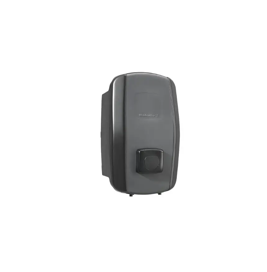
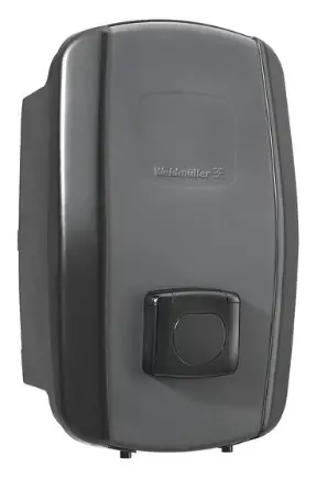
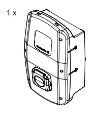
Weidm ller Wallbox AC SMART
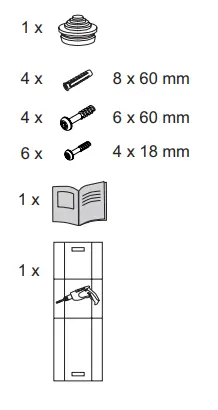
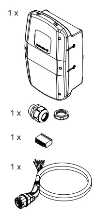
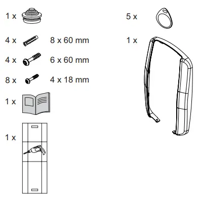
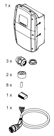
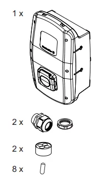
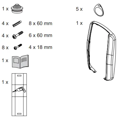
Scope of delivery
- ECO

- PLUG

- SOCKET

- VALUE

- PLUG

- SOCKET

- ADVANCED
- PLUG

- SOCKET

Safety note
These instructions are part of the product.
- If you hand over the product to a third party, always hand over the instructions as well. These instructions are intended for the installer of the product.
- Read the instructions completely before you install and start using the product.
- Check with the responsible grid operator regarding applicable regulations and provisions for charging boxes.
- You can download an acceptance protocol for initial commissioning from the Weidmüller website.
 | The operating instructions can be downloaded from the Weidmüller product catalogue. |
 | Assembly and installation may only be carried out by an electrician. |
![]()
Risk to life due to electric shock
There is a risk of electric shock when working on the electrical installation of the product.
- Ensure that the following equipment is present in the domestic installation:
- one ground residual current protective switch for each charging point in accordance with DIN EN 61008-1, DIN EN 61009-1
- one circuit breaker for each charging point in accordance with DIN EN 60898, DIN EN 60947-2
- Ensure that voltage is switched off to the product and feed line before beginning assembly and installation work on the product.
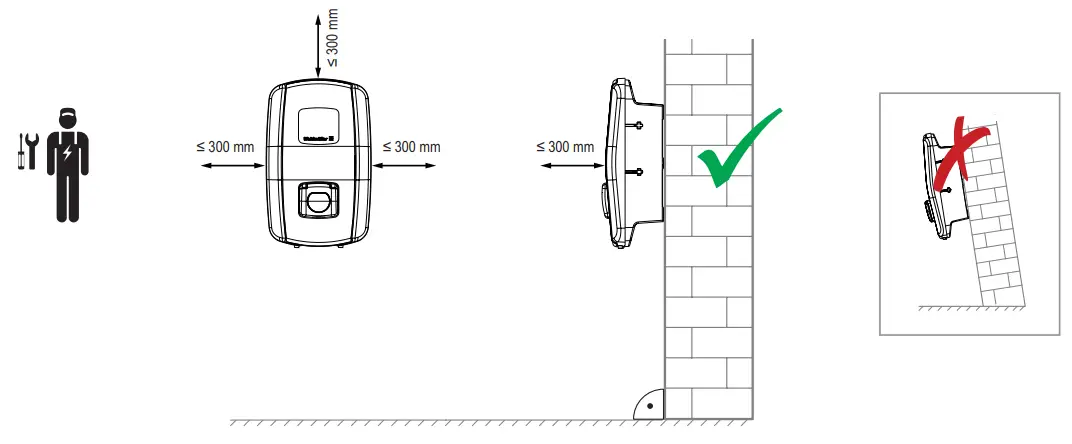
- Observe the requirements for the installation site (see technical data).
- Ensure correct wiring.
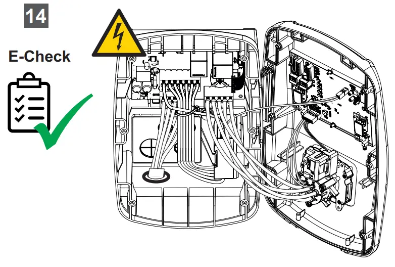
- Carry out a visual inspection and create an acceptance protocol before initial commissioning.
Incorrect installation may cause water to get into the product. This could result in an electric shock.
- The IP protection class is only achieved if the product is assembled and installed as described in this documentation.
- Only install the product in the direction shown in these instructions.
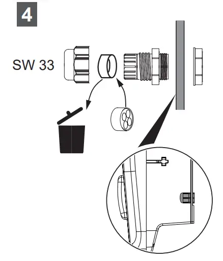
- Only use the cable bushings with suitable cable glands and sealing elements. Ensure correct installation.
- Only operate the product if it has been assembled and installed as described in this documentation.
- Do not use a pressure washer to clean the EV charging box.
- Only clean the EV charging box with a soft, lightly moistened cloth.
Risk to life due to fire
Incorrect installation may cause lines to be damaged or the product to overheat. This could result in a fire.
- Observe the requirements for the installation site (see technical data).
- Only install the product in the direction shown in these instructions.
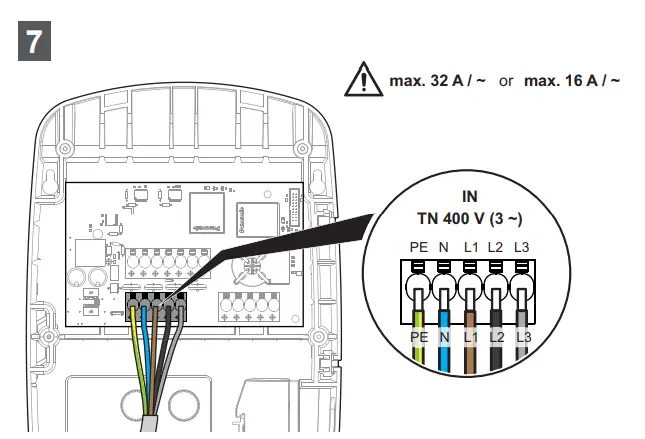
- 16 A variation: install a supply cable with a wire cross-section of at least 2.5 mm2.
- 32 A variation: install a supply cable with a wire cross-section of at least 6 mm2
Foreign objects or dirt in the plug contacts can cause a fire.
- Check the plug contacts for foreign objects and contamination.
- Do not insert any objects into the plug contacts.
- Remove light contamination, for instance dust or sand, by blowing it out.
- Heavy contamination must be cleaned by an electrician
Risk of death due to blocked escape routes
An improper installation site may cause escape routes to become blocked or create a tripping hazard.
- Ensure that the installed product does not block any escape routes.

Risk of injury if product is damaged
A damaged or incomplete product can lead to malfunctions and hazards.
- If you store the product before installation, observe the storage information in these operating instructions.
- Only begin installation if all articles in the scope of delivery are present and complete.
- Only begin installation if all components are free from damage.
- Check the EV charging box and its accessories for obvious damage before each use.
Risk of injury from falling parts
Incorrect installation may cause the product or parts thereof to fall and injure personnel.
- Ensure that the subsurface has a sufficient load-bearing capacity.
- Use the included installation material for installation on a concrete wall (see scope of delivery).
- Use suitable installation material for installation on a wall made of another material. Note the product weight (see technical data).
- Do not place any objects on the installed housing.
![]()
Possible destruction of the product
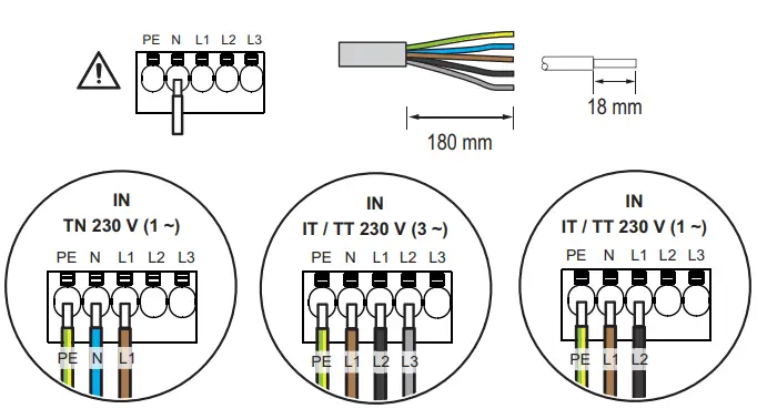
The connection terminals of the neutral conductor must be connected in all network systems. Incorrect installation may cause the destruction of the product.
- Only install the product only as described in these instructions.
Disposal
 | Observe the notes for proper disposal of the product. You can find the notes here: www.weidmueller.com/disposal. |

Safety Precaution
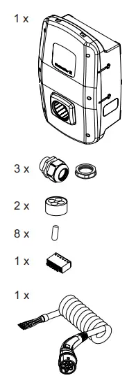
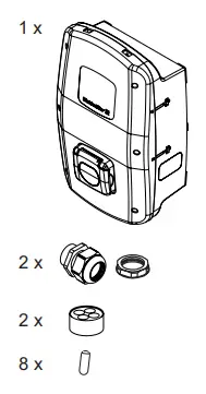
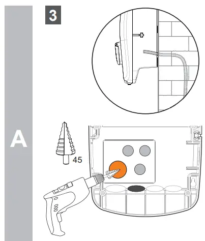
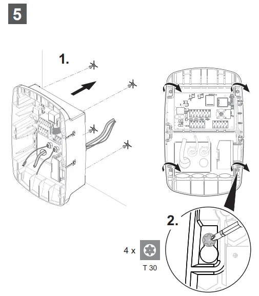
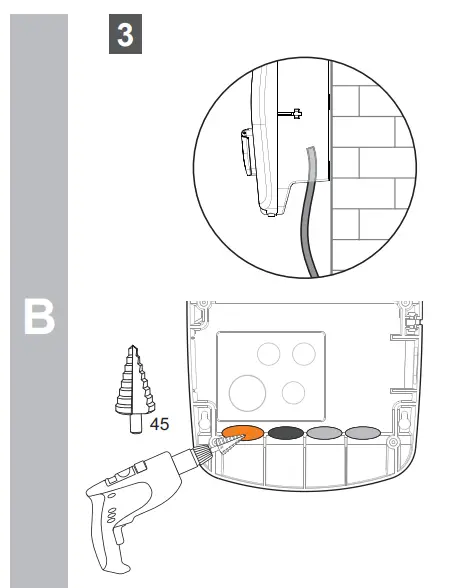
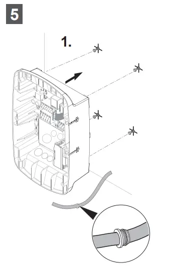
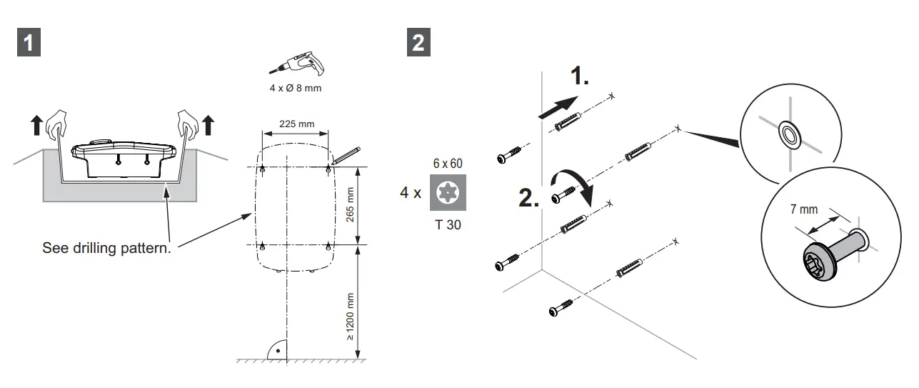
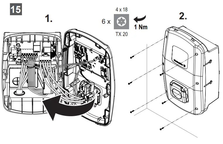
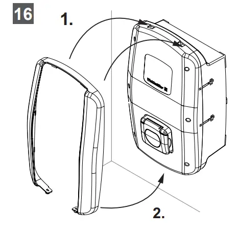
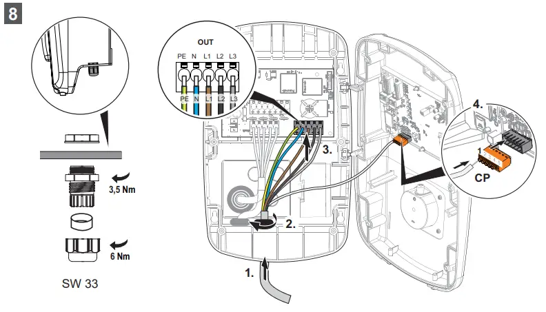
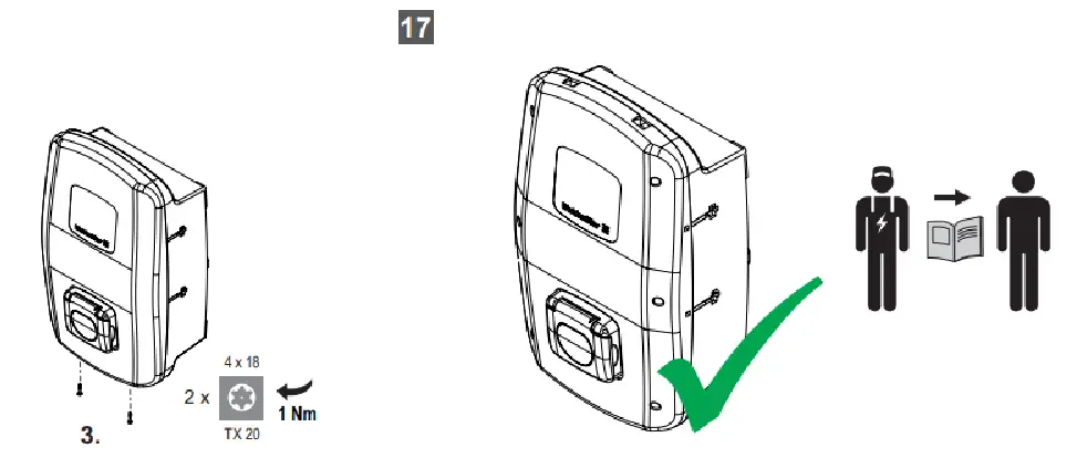
Assembly and installation instructions
 | Power supply cable |
 | Optional cables (communication) |
 | Charging cable (only PLUG variant) |
Optional cable glands (communication)
| Power supply cable |
| Optional cables (communication) |
| Charging cable (only PLUG variant) |
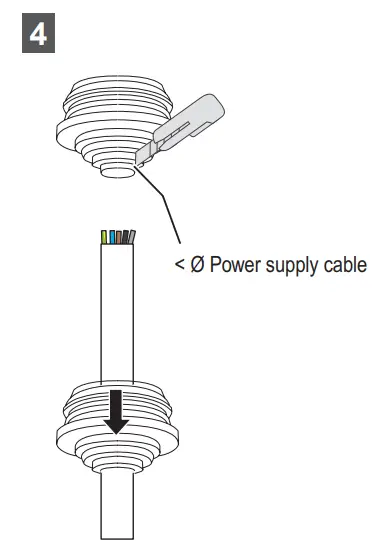
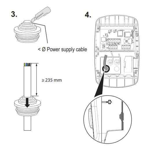
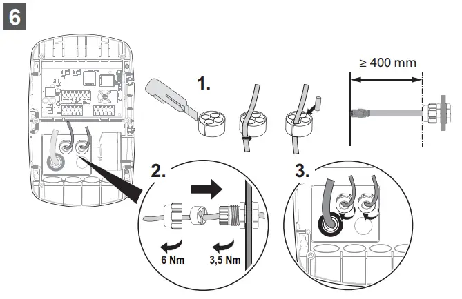
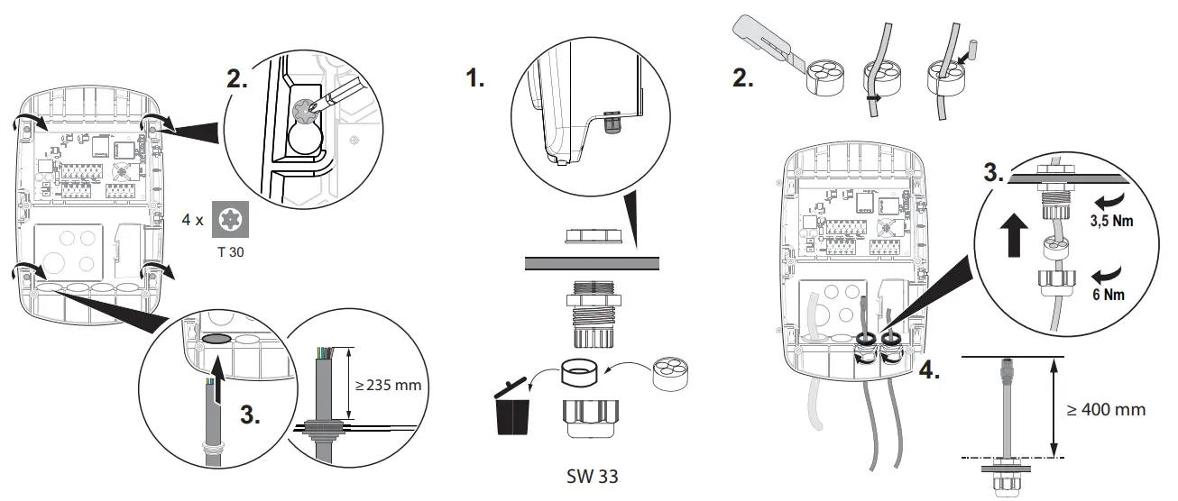
Power supply cable
| 16 A | 32 A | |
| 2,5 mm² – 16 mm² AWG 14 – AWG 4 | 6 mm² – 16 mm² AWG 10 – AWG 4 | |
| 2,5 mm² – 16 mm² | ² 6 mm² – 16 mm² | |
| 6 mm² – 16 mm² | 6 mm² – 16 mm² | |
| 2,5 mm² – 16 mm² | 6 mm² – 16 mm² |
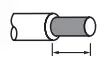
| wire end ferules |  DIN 46 228/4 DIN 46 228/4DIN 46 228/1 | ||
 |  |  | Order no. |
| 2,5 mm² | 20 mm 18 mm | H2,5/25T GR H2,5/18 | 9021090000 9004090000 |
| 6 mm² | 20 mm 18 mm | H6,0/26 SW H6,0/18 | 0565700000 9004130000 |
| 10 mm² | 21 mm 18 mm | H10,0/28 EB H10,0/18 | 0565800000 0379300000 |
| 16 mm² | 21 mm 18 mm | H16,0/28 GN H16,0/18 | 0566000000 0375200000 |
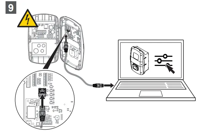
Optional: Limit max. charging current, charging phases and max. assymetrical current / configure network settings
Web server: 192.168.0.8
Role: Admin
Password: zyVt45Nv0y
In order to prevent unauthorised access you should change the login data immediately.
Go to charge settings:
Config / General / Charge settings / Installation current limit [A]
Config / General / Charge settings / Charging phases
Config / General / Charge settings / Max current asymmetrical [A]
Optional: Cover VALUE / ADVANCED
Only PLUG variant
Download:

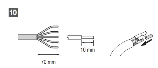
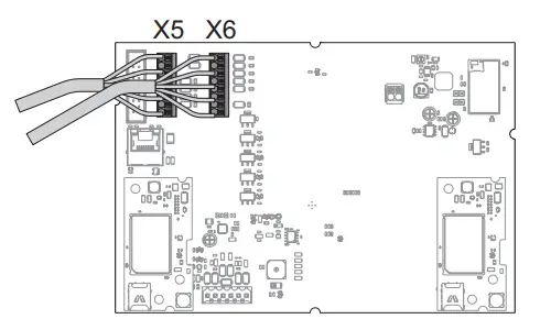
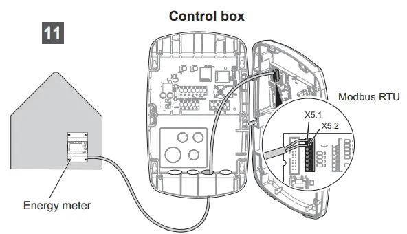
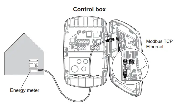
Optional: Signal cable / data cable
| Pos. | Label | Function | |
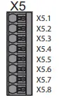 | X5.1 | B | RS485 Modbus RTU Signal B/- |
| X5.2 | A | RS485 Modbus RTU Signal A/+ | |
| X5.3 | GND | Ground | |
| X5.4 | RED | Digital output, status LED red | |
| X5.5 | GN | Digital output, status LED green | |
| X5.6 | BL | Digital output, status LED blue | |
| X5.7 | DO | Digital output, configurable | |
| X5.8 | GND | Ground |
| Pos. | Label | Function | |
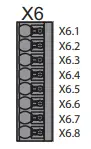 | X6.1 | DI1 | Digital input, configurable, 12 V |
| X6.2 | DI2 | Digital input, configurable, 12 V | |
| X6.3 | DI3 | Digital input, configurable, 12 V | |
| X6.4 | DI4 | Digital input, configurable, 12 V | |
| X6.5 | DI5 | Digital input, configurable, 12 V | |
| X6.6 | GND | Ground | |
| X6.7 | 12V | Supply voltage 12 V | |
| X6.8 | 12V | Supply voltage 12 V |
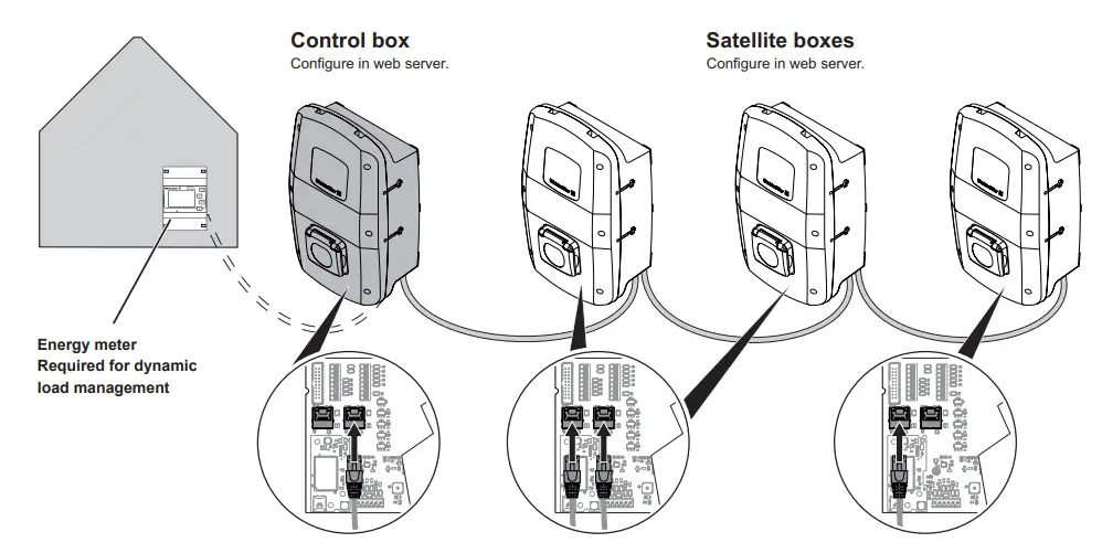
Optional: Energy meter VALUE / ADVANCED
| Signal / data cable | |
| 0,13 mm² – 1,5 mm² AWG 28 – AWG 14 | |
| 0,2 mm² – 1,5 mm² | |
| 0.2 mm² – 1,5 mm² |
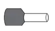
| wire end ferules |  DIN 46 228/4 DIN 46 228/4 | ||
| | Order no. | |
| 0,25 mm² | 10 mm | H0,25/12 HBL | 9025760000 |
| 0,34 mm² | 10 mm | H0,34/12 TK | 9025770000 |
| 0,5 mm² | 10 mm | H0,5/14 OR | 0690700000 |
| 0,75 mm² | 10 mm | H0,75/14T HBL | 9021040000 |
Optional: Load management / charge management VALUE / ADVANCED
Load management / charge management | |
| VALUE | static |
| ADVANCED | dynamic |
Technical data
Charging current, max.
- Width x height x depth
- Weight
- Housing impact resistance rating
- Operating temperature
- Storage temperature
- Relative humidity during operation
- Relative humidity during storage
- Degree of protection
- Pollution severity
- Protection degree
- Phases
- Rated voltage
- Rated current
- Rated impulse voltage
- Insulation voltage
- Overvoltage category
- Mains frequency
- Circuit breaker max. 1)
- Charging voltage
- Charging power, max.
- Short circuit current C16/C32 (energy limit class 3)
- AC residual current protective switch 1)
- DC fault-current detection integrated
- Network design
- Charging mode
- Supported charging states
- EMC classification
- Socket in accordance with IEC 62196-1:2014 for charging cable
- Plug in accordance with IEC 62196-1:2014 for charging cable
- Permitted setup area
- Static load/charge management integrated
- Dynamic load/charge management integrated
- MD conforming energy meter integrated
- Mobile app
- Supported network protocols
- Mobile phone
- Interfaces
- Digital inputs
- Digital outputs
must be present in the domestic installation
ADVANCED | |||
| Plug | Socket | ||
| 16 A | 32 A | 16 A | 32 A |
| 273 x 439 x 150 mm (167 mm inkl. cover) | 273 x 439 x 150 mm (167 mm inkl. cover) | ||
| 11 kW: 5.6 kg 22 kW: 6.9 kg | 11 kW: 4.3 kg 22 kW: 4.3 kg | ||
| IK10 | IK10 | ||
| -25 °C bis +45 °C | -25 °C bis +45 °C | ||
| -25 °C bis +70 °C | -25 °C bis +70 °C | ||
| 5 … 95 % (non-condensing) | 5 … 95 % (non-condensing) | ||
| 5 … 95 % (non-condensing) | 5 … 95 % (non-condensing) | ||
| IP54 | IP54 | ||
| 3 | 3 | ||
| I | I | ||
| 1… 3 | 1… 3 | ||
| 207 … 253 V / 360 … 440 V | 207 … 253 V / 360 … 440 V | ||
| 16 A | 32 A | 16 A | 32 A |
| 4 kV | 4 kV | ||
| 500 V | 500 V | ||
| III | III | ||
| 50 / 60 Hz | 50 / 60 Hz | ||
| 16 A | 32 A | 16 A | 32 A |
| 230 / 400 V | 230 / 400 V | 230 / 400 V | 230 / 400 V |
| 11 kW | 22 kW | 11 kW | 22 kW |
| 6 kA | 6 kA | ||
| Type A 30 mA | Type A 30 mA | ||
| 6 mA | 6 mA | ||
| TN / TT / IT | TN / TT / IT | ||
| 3 | 3 | ||
| A, B, C, E, F | A, B, C, E, F | ||
| Class B | Class B | ||
| – | Type 2 | ||
| Type 2 | – | ||
| indoor, outdoor | indoor, outdoor | ||
| x | x | ||
| x | x | ||
| x | x | ||
| x | x | ||
| Modbus RTU / TCP, OCPP 1.6 (J) | Modbus RTU / TCP, OCPP 1.6 (J) | ||
| x | x | ||
| Bluetooth (Low Energy), WLAN (802.11 b/g/n), 2 x LAN / Ethernet, 1 x RS 485 | Bluetooth (Low Energy), WLAN (802.11 b/g/n), 2 x LAN / Ethernet, 1 x RS 485 | ||
| 5 x 12 V / 6 mA | 5 x 12 V / 6 mA | ||
| 4 x 12 V / 100 mA | 4 x 12 V / 100 mA | ||
Customer Support
Weidmüller Interface GmbH & Co. KG
Klingenbergstraße 26
32758 Detmold, Deutschland
T +49 (0)5231 14-0
F +49 (0)5231 14-292083
www.weidmueller.com


![Midea Smart Ac [cw058iu-awifi] User Manual](https://static-data1.manualsee.com/1/img/294/17740/2020/12/Midea-Smart-AC-CW058IU-AWIFI.png "Midea Smart Ac [cw058iu-awifi] User Manual")


