VISHAY SMCJ5.0A thru SMCJ188CA Surface Mount TRANSZORB Transient Voltage Suppressors

Product Information
- Product Name: SMCJ5.0A thru SMCJ188CA
- Manufacturer: Vishay General Semiconductor
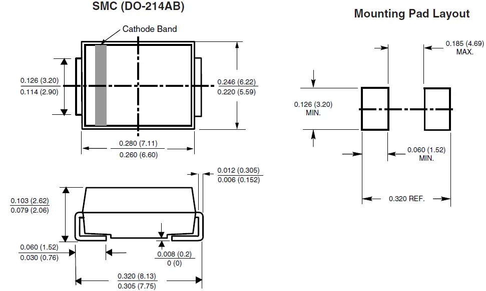
- Package Type: SMC (DO-214AB)
- Polarity: Unidirectional (cathode),
Bidirectional (anode) - Breakdown Voltage (VBR): 6.40 V to 231 V
(unidirectional), 5.0 V to 188 V (bidirectional) - Peak Pulse Power Dissipation (PPPM): 1500 W
- Peak Pulse Current (IFSM): 200 A
(unidirectional only) - Operating Junction and Storage Temperature
Range: -55°C to +150°C
Product Usage Instructions
The SMCJ5.0A thru SMCJ188CA diodes are designed for use in sensitive electronics to protect against voltage transients induced by inductive load switching and lighting on ICs, MOSFETs, signal lines of sensor units, and more. Follow the instructions below to use the product effectively:
- Select the appropriate diode based on the desired breakdown voltage (VBR) range.
- Ensure correct polarity placement: For unidirectional types, the band denotes the cathode end. There is no marking on bidirectional types.
- Solder the diode using matte tin plated leads, following J-STD-002 and JESD 22-B102 standards.
- Ensure proper temperature management within the operating junction and storage temperature range of -55°C to +150°C.
Please refer to the product manual or contact Vishay General Semiconductor for any technical questions or clarifications.
PRIMARY CHARACTERISTICS
| VBR unidirectional | 6.40 V to 231 V |
| VBR bidirectional | 6.40 V to 231 V |
| VWM | 5.0 V to 188 V |
| PPPM | 1500 W |
| PD | 6.5 W |
| IFSM (unidirectional only) | 200 A |
| TJ max. | 150 °C |
| Polarity | Unidirectional, bidirectional |
| Package | SMC (DO-214AB) |
DEVICES FOR BIDIRECTION APPLICATIONS
For bidirectional devices use CA suffix (e.g. SMCJ188CA). Electrical characteristics apply in both directions.
FEATURES
- Low profile package
- Ideal for automated placement
- Glass passivated chip junction
- Available in unidirectional and bidirectional
- Excellent clamping capability
- Very fast response time
- Low incremental surge resistance
- Meets MSL level 1, per J-STD-020, LF maximum peak of 260 °C
- AEC-Q101 qualified available
- Automotive ordering code: base P/NHE3 or P/NHM3
- Material categorization: for definitions of compliance please see www.vishay.com/doc?9991
TYPICAL APPLICATIONS
Use in sensitive electronics protection against voltage transients induced by inductive load switching and lightin g on ICs, MOSFET, signal lines of sensor units for consumer, computer, industrial, automotive, and telecommunication.
MECHANICAL DATA
Case: SMC (DO-214AB)
Molding compound meets UL 94 V-0 flammability rating Base P/N-E3 – RoHS-compliant, commercial grade
Base P/N-M3 – halogen-free, RoHS-compliant, commercial grade
Base P/NHE3_X – RoHS-compliant and AEC-Q101 qualified Base P/NHM3_X – halogen-free, RoHS-compliant, an d AEC-Q101 qualified
(“_X” denotes revision code e.g. A, B, …)
Terminals: matte tin plated leads, solderable per J-STD-002 and JESD 22-B102
E3, M3, HE3, and HM3 suffix meets JESD 201 class 2 whisker test
Polarity: for unidirectional types the band denotes cathode end, no marking on bidirectional types
| MAXIMUM RATINGS (TA = 25 °C unless otherwise noted) | |||
| PARAMETER | SYMBOL | VALUE | UNIT |
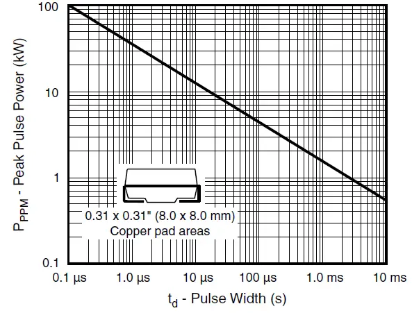
| Peak pulse power dissipation with a 10/1000 μs waveform (1)(2) | PPPM | 1500 | W |
| Peak pulse current with a 10/1000 μs waveform (1) | IPPM | See next table | A |
| Power dissipation on infinite heatsink, TA = 50 °C | PD | 6.5 | W |
| Peak forward surge current 8.3 ms single half sine-wave unidirectional only (2) | IFSM | 200 | A |
| Operating junction and storage temperature range | TJ, TSTG | -55 to +150 | °C |
| ELECTRICAL CHARACTERISTICS (TA = 25 °C unless otherwise noted) | ||||||||||
| DEVICE TYPE MODIFIED “J” BEND LEAD | DEVICE MARKING CODE | BREAKDOWN VOLTAGE VBR AT IT (1) (V) | TEST CURRENT IT (mA) | STAND-OFF VOLTAGE VWM (V) | MAXIMUM REVERSE LEAKAGE AT VWM ID (μA) (3) | MAXIMUM PEAK PULSE SURGE CURRENT IPPM (A) (2) | MAXIMUM CLAMPING VOLTAGE AT IPPM VC (V) | MAXIMUM TEMPERATURE COEFFICIENT OF VBR (%/°C) | ||
| UNI | BI | MIN. | MAX. | |||||||
| (+)SMCJ5.0A (5) | GDE | GDE | 6.40 | 7.07 | 10 | 5.0 | 1000 | 163.0 | 9.2 | 0.057 |
| (+)SMCJ6.0A | GDG | GDG | 6.67 | 7.37 | 10 | 6.0 | 1000 | 145.6 | 10.3 | 0.059 |
| (+)SMCJ6.5A | GDK | BDK | 7.22 | 7.98 | 10 | 6.5 | 500 | 133.9 | 11.2 | 0.061 |
| (+)SMCJ7.0A | GDM | GDM | 7.78 | 8.60 | 10 | 7.0 | 200 | 125.0 | 12.0 | 0.065 |
| (+)SMCJ7.5A | GDP | BDP | 8.33 | 9.21 | 1.0 | 7.5 | 100 | 116.3 | 12.9 | 0.067 |
| (+)SMCJ8.0A | GDR | BDR | 8.89 | 9.83 | 1.0 | 8.0 | 50 | 110.3 | 13.6 | 0.069 |
| (+)SMCJ8.5A | GDT | BDT | 9.44 | 10.4 | 1.0 | 8.5 | 20 | 104.2 | 14.4 | 0.073 |
| (+)SMCJ9.0A | GDV | BDV | 10.0 | 11.1 | 1.0 | 9.0 | 10 | 97.4 | 15.4 | 0.074 |
| (+)SMCJ10A | GDX | BDX | 11.1 | 12.3 | 1.0 | 10 | 5.0 | 88.2 | 17.0 | 0.078 |
| (+)SMCJ11A | GDZ | GDZ | 12.2 | 13.5 | 1.0 | 11 | 5.0 | 82.4 | 18.2 | 0.080 |
| (+)SMCJ12A | GEE | BEE | 13.3 | 14.7 | 1.0 | 12 | 5.0 | 75.4 | 19.9 | 0.083 |
| (+)SMCJ13A | GEG | GEG | 14.4 | 15.9 | 1.0 | 13 | 1.0 | 69.8 | 21.5 | 0.084 |
| (+)SMCJ14A | GEK | BEK | 15.6 | 17.2 | 1.0 | 14 | 1.0 | 64.7 | 23.2 | 0.087 |
| (+)SMCJ15A | GEM | BEM | 16.7 | 18.5 | 1.0 | 15 | 1.0 | 61.5 | 24.4 | 0.088 |
| (+)SMCJ16A | GEP | GEP | 17.8 | 19.7 | 1.0 | 16 | 1.0 | 57.7 | 26.0 | 0.089 |
| (+)SMCJ17A | GER | GER | 18.9 | 20.9 | 1.0 | 17 | 1.0 | 54.3 | 27.6 | 0.090 |
| (+)SMCJ18A | GET | BET | 20.0 | 22.1 | 1.0 | 18 | 1.0 | 51.4 | 29.2 | 0.092 |
| (+)SMCJ20A | GEV | BEV | 22.2 | 24.5 | 1.0 | 20 | 1.0 | 46.3 | 32.4 | 0.094 |
| (+)SMCJ22A | GEX | BEX | 24.4 | 26.9 | 1.0 | 22 | 1.0 | 42.3 | 35.5 | 0.096 |
| (+)SMCJ24A | GEZ | BEZ | 26.7 | 29.5 | 1.0 | 24 | 1.0 | 38.6 | 38.9 | 0.096 |
| (+)SMCJ26A | GFE | BFE | 28.9 | 31.9 | 1.0 | 26 | 1.0 | 35.6 | 42.1 | 0.097 |
| (+)SMCJ28A | GFG | BFG | 31.1 | 34.4 | 1.0 | 28 | 1.0 | 33.0 | 45.4 | 0.098 |
| (+)SMCJ30A | GFK | BFK | 33.3 | 36.8 | 1.0 | 30 | 1.0 | 31.0 | 48.4 | 0.099 |
| (+)SMCJ33A | GFM | BFM | 36.7 | 40.6 | 1.0 | 33 | 1.0 | 28.1 | 53.3 | 0.100 |
| (+)SMCJ36A | GFP | BFP | 40.0 | 44.2 | 1.0 | 36 | 1.0 | 25.8 | 58.1 | 0.100 |
| (+)SMCJ40A | GFR | BFR | 44.4 | 49.1 | 1.0 | 40 | 1.0 | 23.3 | 64.5 | 0.101 |
| (+)SMCJ43A | GFT | BFT | 47.8 | 52.8 | 1.0 | 43 | 1.0 | 21.6 | 69.4 | 0.102 |
| (+)SMCJ45A | GFV | GFV | 50.0 | 55.3 | 1.0 | 45 | 1.0 | 20.6 | 72.7 | 0.102 |
| (+)SMCJ48A | GFX | GFX | 53.3 | 58.9 | 1.0 | 48 | 1.0 | 19.4 | 77.4 | 0.103 |
| (+)SMCJ51A | GFZ | GFZ | 56.7 | 62.7 | 1.0 | 51 | 1.0 | 18.2 | 82.4 | 0.104 |
| (+)SMCJ54A | GGE | GGE | 60.0 | 66.3 | 1.0 | 54 | 1.0 | 17.2 | 87.1 | 0.104 |
| (+)SMCJ58A | GGG | GGG | 64.4 | 71.2 | 1.0 | 58 | 1.0 | 16.0 | 93.6 | 0.104 |
| (+)SMCJ60A | GGK | GGK | 66.7 | 73.7 | 1.0 | 60 | 1.0 | 15.5 | 96.8 | 0.105 |
| (+)SMCJ64A | GGM | GGM | 71.1 | 78.6 | 1.0 | 64 | 1.0 | 14.6 | 103 | 0.105 |
| (+)SMCJ70A | GGP | GGP | 77.8 | 86.0 | 1.0 | 70 | 1.0 | 13.3 | 113 | 0.105 |
| (+)SMCJ75A | GGR | GGR | 83.3 | 92.1 | 1.0 | 75 | 1.0 | 12.4 | 121 | 0.106 |
| (+)SMCJ78A | GGT | GGT | 86.7 | 95.8 | 1.0 | 78 | 1.0 | 11.9 | 126 | 0.106 |
| (+)SMCJ85A | GGV | GGV | 94.4 | 104 | 1.0 | 85 | 1.0 | 10.9 | 137 | 0.106 |
| (+)SMCJ90A | GGX | GGX | 100 | 111 | 1.0 | 90 | 1.0 | 10.3 | 146 | 0.106 |
| (+)SMCJ100A | GGZ | GGZ | 111 | 123 | 1.0 | 100 | 1.0 | 9.3 | 162 | 0.107 |
| (+)SMCJ110A | GHE | GHE | 122 | 135 | 1.0 | 110 | 1.0 | 8.5 | 177 | 0.107 |
| (+)SMCJ120A | GHG | GHG | 133 | 147 | 1.0 | 120 | 1.0 | 7.8 | 193 | 0.108 |
| (+)SMCJ130A | GHK | GHK | 144 | 159 | 1.0 | 130 | 1.0 | 7.2 | 209 | 0.108 |
| (+)SMCJ150A | GHM | GHM | 167 | 185 | 1.0 | 150 | 1.0 | 6.2 | 243 | 0.108 |
| (+)SMCJ160A | GHP | GHP | 178 | 197 | 1.0 | 160 | 1.0 | 5.8 | 259 | 0.108 |
| (+)SMCJ170A | GHR | GHR | 189 | 209 | 1.0 | 170 | 1.0 | 5.5 | 275 | 0.108 |
| SMCJ188A | GHS | GHS | 209 | 231 | 1.0 | 188 | 1.0 | 4.6 | 328 | 0.108 |
Notes
- Pulse test: tp ≤ 50 ms
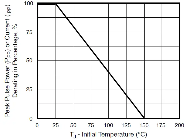
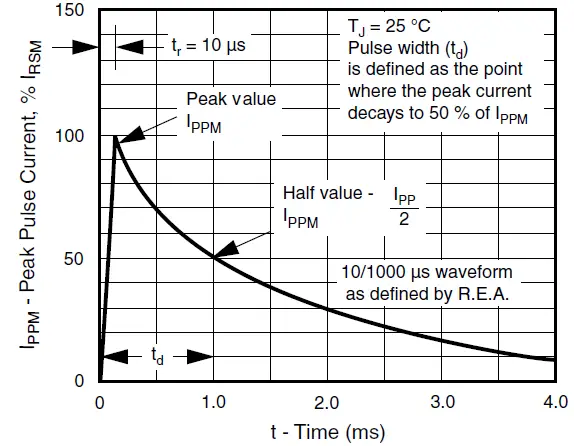
- Surge current waveform per fig. 3 and derate per fig. 2
- For bidirectional types having VWM of 10 V and less, the ID limit is doubled
- All terms and symbols are consistent with ANSI/IEEE C62.35
- For the bidirectional SMCJ5.0CA, the maximum VBR is 7.25 V
- VF = 3.5 V at IF = 100 A (unidirectional only)
(+) Underwriters laboratory recognition for the classification of protectors (QVGQ2) under the UL standard for safety 497B and file number
| THERMAL CHARACTERISTICS (TA = 25 °C unless otherwise noted) | |||
| PARAMETER | SYMBOL | VALUE | UNIT |
| Typical thermal resistance, junction to ambient air (1) | RqJA | 75 | °C/ W |
| Typical thermal resistance, junction to lead | RqJL | 15 | |
Note
- Mounted on minimum recommended pad layout
| ORDERING INFORMATION (Example) | ||||
| PREFERRED P/N | UNIT WEIGHT (g) | PREFERRED PACKAGE CODE | BASE QUANTITY | DELIVERY MODE |
| SMCJ5.0A-E3/57T | 0.211 | 57T | 850 | 7″ diameter plastic tape and reel |
| SMCJ5.0A-M3/57T | ||||
| SMCJ5.0A-E3/9AT | 0.211 | 9AT | 3500 | 13″ diameter plastic tape and reel |
| SMCJ5.0A-M3/9AT | ||||
| SMCJ5.0AHE3_A/H (1) | 0.211 | H | 850 | 7″ diameter plastic tape and reel |
| SMCJ5.0AHM3_A/H (1) | ||||
| SMCJ5.0AHE3_A/I (1) | 0.211 | I | 3500 | 13″ diameter plastic tape and reel |
| SMCJ5.0AHM3_A/I (1) | ||||
RATINGS AND CHARACTERISTICS CURVES
(TA = 25 °C unless otherwise noted)
- Peak Pulse Power Rating Curve

- Pulse Power or Current vs. Initial Junction Temperature

- Pulse Waveform

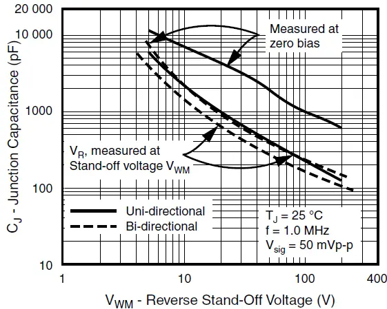
- Typical Junction Capacitance Unidirectional

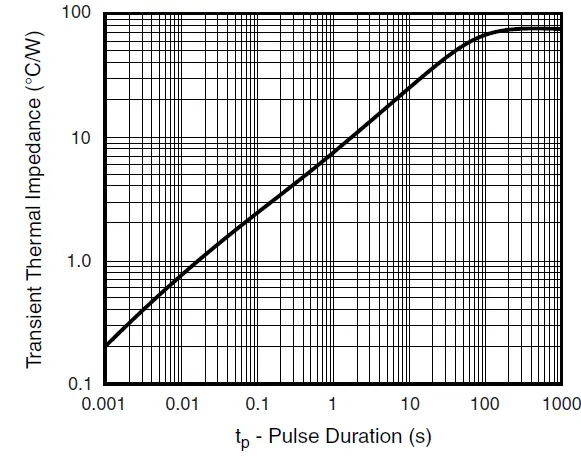
- Typical Transient Thermal Impedance

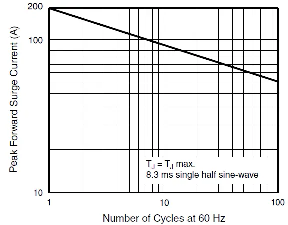
- Maximum Non-Repetitive Peak Forward Surge Current Unidirectional Use On

PACKAGE OUTLINE DIMENSIONS
in inches (millimeters)