
JBL Professional CSA 2300Z Power Amplifier

IMPORTANT SAFETY INFORMATION
WARNING
RISK OF ELECTRIC SHOCK
DO NOT OPEN
WARNING: TO REDUCE THE RISK OF FIRE OR ELECTRIC
SHOCK DO NOT EXPOSE THIS EQUIPMENT TO RAIN OR MOISTURE
NOTICE FOR CUSTOMERS IF YOUR UNIT IS EQUIPPED WITH A POWER CORD.
WARNING: THIS APPLIANCE SHALL BE CONNECTED TO A MAINS SOCKET OUTLET WITH A PROTECTIVE EARTHING CONNECTION.
The cores in the mains lead are colored in accordance with the following code:
- GREEN and YELLOW – Earth
- BLUE – Neutral
- BROWN – Live
As colors of the cores in the mains lead of this appliance may not cor-respond with the colored markings identifying the terminals in your plug, proceed as follows:
- The core which is colored green and yellow must be connected to the terminal in the plug marked with the letter E, or with the earth symbol, or colored green, or green and yellow.
- The core which is colored blue must be connected to the terminal marked N or colored black.
The core which is colored brown must be connected to the terminal marked L or colored red.
This equipment may require the use of a different line cord, attachment plug, or both, depending on the available power source at installation. If the attachment plug needs to be changed, refer servicing to qualified service personnel who should refer to the table below. The green/yellow wire shall be connected directly to the unit’s chassis.
| CONDUCTOR | WIRE COLOR | ||
| Normal | Alt | ||
| L | LIVE | BROWN | BLACK |
| N | NEUTRAL | BLUE | WHITE |
| E | EARTH GND | GREEN/YEL | GREEN |
WARNING: If the ground is defeated, certain fault conditions in the unit or in the system to which it is connected can result in full line voltage between the chassis and earth ground. Severe injury or death can then result if the chassis and earth ground are touched simultaneously.
WARNING FOR YOUR PROTECTION READ THESE INSTRUCTIONS:
- KEEP THESE INSTRUCTIONS
- HEED ALL WARNINGS
- FOLLOW ALL INSTRUCTIONS
- THE APPARATUS SHALL NOT BE EXPOSED TO DRIPPING OR SPLASHING LIQUID AND NO OBJECT FILLED WITH LIQUID, SUCH AS VASES, SHALL BE PLACED ON THE APPARATUS
- CLEAN ONLY WITH A DRY CLOTH.
- DO NOT BLOCK ANY OF THE VENTILATION OPENINGS. INSTALL IN ACCORDANCE WITH THE MANUFACTURER’S INSTRUCTIONS.
- DO NOT INSTALL NEAR ANY HEAT SOURCES SUCH AS RADIATORS, HEAT REGISTERS, STOVES, OR OTHER APPARATUS (INCLUDING AMPLIFIERS) THAT PRODUCE HEAT.
- ONLY USE ATTACHMENTS/ACCESSORIES SPECIFIED BY THE MANUFACTURER.
- UNPLUG THIS APPARATUS DURING LIGHTNING STORMS OR WHEN UNUSED FOR LONG PERIODS OF TIME.
- Do not defeat the safety purpose of the polarized or grounding-type plug. A polarized plug has two blades with one wider than the other. A grounding type plug has two blades and a third grounding prong. The wide blade or third prong are provided for your safety. If the provided plug does not fit your outlet, consult an electrician for the replacement of the obsolete outlet.
- Protect the power cord from being walked on or pinched particularly at plugs, convenience receptacles, and the point where they exit from the apparatus.
- Use only with the cart stand, tripod bracket, or table specified by the manufacturer, or sold with the apparatus. When a cart is used, use caution when moving the cart/apparatus combination to avoid injury from tip-over. Refer all servicing to qualified service personnel. Servicing is required when the apparatus has been damaged in any way, such as power-supply cord or plug is damaged, liquid has been spilled or objects have fallen into the apparatus, the apparatus has been exposed to rain or moisture, does not operate normally, or has been dropped.
- POWER ON/OFF SWITCH: For products provided with a power switch, the power switch DOES NOT break the connection from the mains.
- MAINS DISCONNECT: The plug shall remain readily operable. For rack-mount or installation where plug is not accessible, an all-pole mains switch with a contact separation of at least 3 mm in each pole shall be incorporated into the electrical installation of the rack or building.
- FOR UNITS EQUIPPED WITH EXTERNALLY ACCESSIBLE FUSE RECEPTACLE: Replace fuse with same type and rating only.
- MULTIPLE-INPUT VOLTAGE: This equipment may require the use of a different line cord, attachment plug, or both, depending on the available power source at installation. Connect this equipment only to the power source indicated on the equipment’s rear panel. To reduce the risk of fire or electric shock, refer servicing to qualified service personnel or equivalent.
If connected to 240V supply, a suitable CSA/UL certified power cord shall be used for this supply.
- MULTIPLE-INPUT VOLTAGE: This equipment may require the use of a different line cord, attachment plug, or both, depending on the available power source at installation. Connect this equipment only to the power source indicated on the equipment’s rear panel. To reduce the risk of fire or electric shock, refer servicing to qualified service personnel or equivalent.
U.K. MAINS PLUG WARNING
A molded mains plug that has been cut off from the cord is unsafe. Discard the mains plug at a suitable disposal facility. NEVER UNDER ANY CIRCUMSTANCES SHOULD YOU INSERT A DAMAGED OR CUT MAINS PLUG INTO A 13 AMP POWER SOCKET. Do not use the mains plug without the fuse cover in place. Replacement fuse covers can be obtained from your local retailer. Replacement fuses are 13 amps and MUST be ASTA approved to BS1362.
ELECTROMAGNETIC
COMPATIBILITY
This device complies with part 15 of the FCC Rules and the Product specifications noted on the Declaration of Conformity. Operation is subject to the following two conditions:
- This device may not cause harmful interference, and
- This device must accept any interference received, including interference that may cause undesired operation. Operation of this unit within significant electromagnetic fields should be avoided.
- Use only shielded interconnecting cables.
If you want to dispose this product, do not mix it with general household waste. There is a separate collection system for used electronic products in accordance with legislation
that requires proper treatment, recovery and recycling. Private household in the 25 member states of the EU, in Switzerland and Norway may return their used electronic products free of charge todesignated collection facilities or to a retailer (if you purchase a similar new one).
For Countries not mentioned above, please contact your local authorities for a correct method of disposal. By doing so you will ensure that your disposed product undergoes the necessary treatment, recovery and recycling and thus prevent potential negative effects on the environment and human health.
MAGNETIC FIELD
CAUTION! Do not locate sensitive high-gain equipment such as preamplifiers or tape decks directly above or below the unit. Because this amplifier has a high power density, it has a strong magnetic field which can induce hum into unshielded devices that are located nearby. The field is strongest just above and below the unit. If an equipment rack is used, we recommend locating the amplifier(s) in the bottom of the rack and the preamplifier or other sensitive equipment at the top.
USE GROUNDED OUTLET ONLY!
Features
- 1 or 2 channel outputs
- Integrated Output Transformer to drive 70V or 100V speaker systems
- Ideal for commercial and industrial use
- System may be expanded by adding JBL Commercial Series Mixers and Mixer-Amplifiers
- Euro-block style input connectors
- Barrier strip output connectors
- Independent Bass and Treble controls for each output channel
- Remote volume control capability using JBL CSR-V module and standard Ethernet cable
- Capable of RS232 control of volume, mute and sleep mode
- Utilizes Crown’s DriveCoreTM technology providing excellent audio performance with high efficiency
- 3-Year Warranty*
*Warranty is only valid within the United States of America. For information on warranty outside of the U.S.A., please contact your local distributor.
Front Panel Controls and Indicators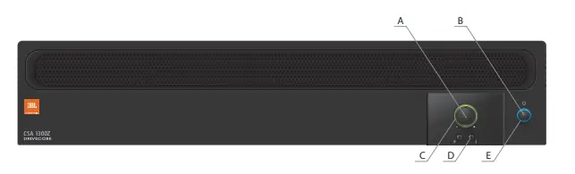
- Output Volume Control
- Power Switch
- The illuminated ring around the output volume control will light green with signal presence while red indicates clipping, i.e. the signal has reached the threshold of audible distortion.
- Tone Controls – Bass
 and
and  Treble potentiometers on each output channel
 - An illuminated ring around the power switch. Blue indicates that the unit is on and in normal operating mode. Green indicates that the unit is connected to the AC mains and has been placed into sleep mode via the RS232 control.
Rear Panel Controls and Connectors 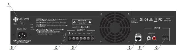
- Circuit breaker reset switch
- AC Power Inlet – Detachable IEC
- 70V/100V Switch – Enables the 70V and 100V outputs and activates the 70Hz high pass filter
- Amplifier Output Connector
- Remote Volume Connector – RJ-45 style connector to connect to JBL CSR-V control module or RS232 controller
- Dual RCA Input Connector – Stereo, unbalanced sources will be summed
- Audio Input Connector – 3 pin Euro-block connector, balanced input.
Setup
Unpacking Your Amplifier
Please unpack and inspect your amplifier for any damage that may have occurred during transit. If damage is found, notify the transportation company immediately. Only you can initiate a claim for shipping damage. We will be happy to help
as needed. Save the shipping carton as evidence of damage for the shipper’s inspection.
We also recommend that you save all packing materials so you will have them if you ever need to transport the unit. Never ship the unit without the factory pack.
WARNING: Before you start to set up your amplifier, make sure you read and observe the Important Safety Instructions found at the beginning of this manual.
Installing Your Amplifier
CAUTION: Before you begin, make sure your amplifier is disconnected from the power source and all level controls turned completely down (counterclockwise).
To install the amplifier, you can use one of the following approaches:
- Rack mount the amplifier with the rack mounting kit, see Figure 2.2.2.
- Place a single amplifier on a surface with 12 inches of air space around the unit for convection cooling. Rubber feet are included and can be attached onto the underside of the chassis. For amplifier dimensions, see Figure 2.2.1.
Figure 2.2.1 Dimensions Figure 2.2.2 Rack Mounting
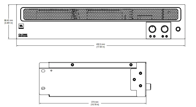 Figure 2.2.2 Rack Mounting
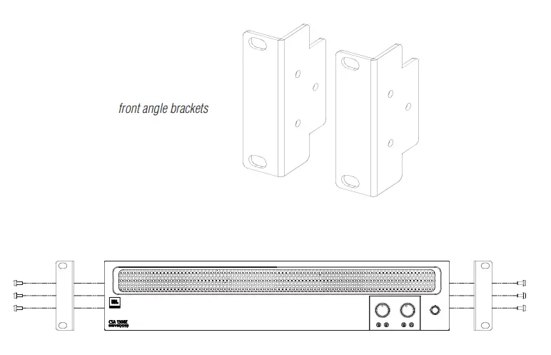
Ensuring Proper Cooling
When using an equipment rack, keep a minimum space of 4 inches (10cm) from the top surface of the unit. Close any open spaces in the rack with blank panels. DO NOT block any air vents. The side walls of the rack should be a minimum of 2 inches (5 cm) from the amplifier sides. The back of the rack should be open.
Choosing Input Wire and Connectors
We recommend using prebuilt or professionally wired balanced line (two-conductor plus shield) 22-24 gauge cables to connect the amplifier balanced input by using the included Euro-block connectors, see Figure 2.4. Unbalanced lines may be used, but may result in hum or RF noise very long cable runs.
You can also use RCA connectors to connect audio devices, for example, CD/DVD players. However, do not use both Euro-block and RCA audio input connectors on a single channel at the same time.
NOTE: Custom wiring should only be performed by qualified personnel.
Figure 2.4 Input Wiring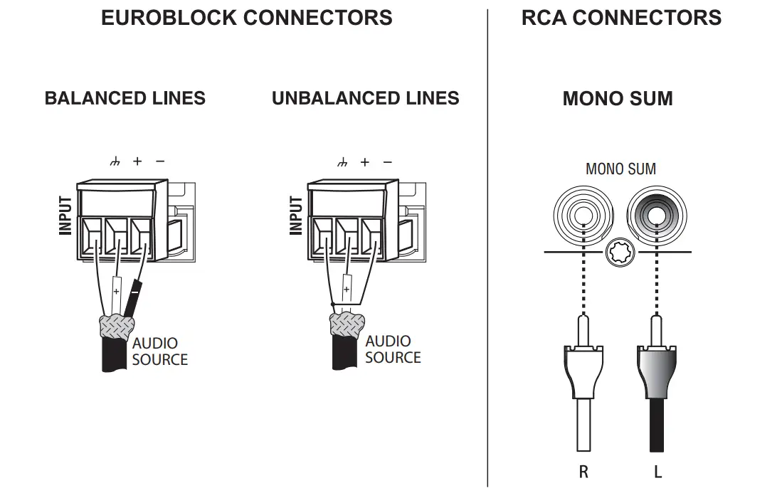 Note: Two RCA connectors are provided for summing left and right channels from a stereo source. Do not use both Euro-block and RCA connectors concurrently for any single input channel.
Output Wiring and Connectors
To drive distributed speaker systems designed to operate at 70V or 100V, connect to the corresponding output terminals.
JBL recommends using prebuilt or professionally wired, high-quality, two-conductor, heavy gauge speaker wire. Speaker wires should be twisted cable, if possible. To prevent the possibility of short circuits, the wires should be stripped back no greater than 6 mm (1/4 inch), see Figure 2.5.
Suggested below are guidelines to select the appropriate size of wire based on the distance from the amplifier to the speaker. Check with the local code as this may vary.
Distance:Wire Size
Up to 25 ft. (7.6m):16AWG
26-40 ft. (7.9-12.2m):14AWG
Figure 2.5 Output Wiring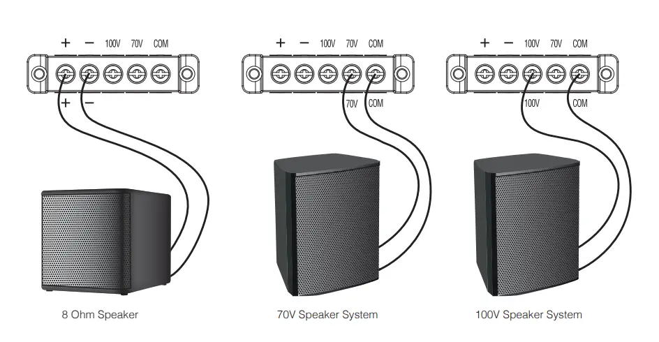 Figure 2.6 Wiring Audio System
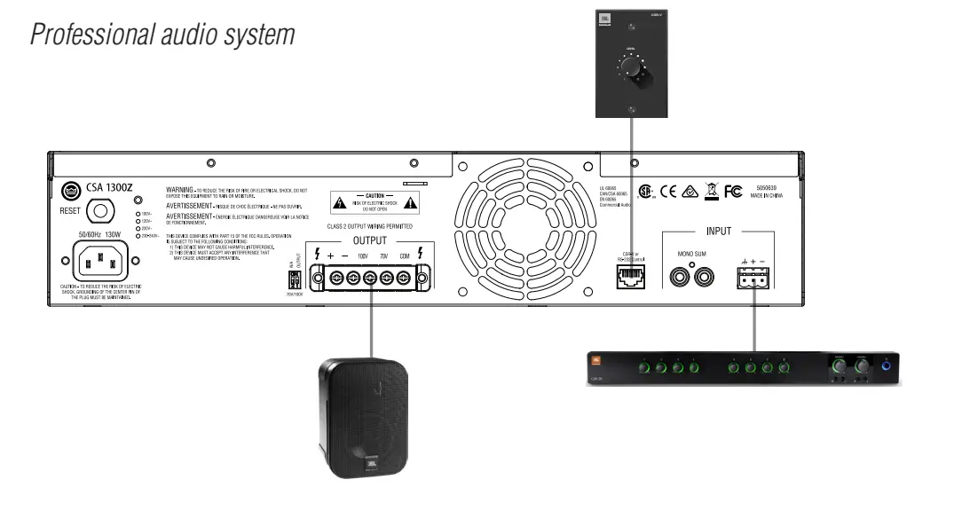
Wiring Your Audio System
Typical input and output wirings are shown in Figure 2.6.
INPUTS: Connect input wiring for both channels using either the RCA or the Euro-block input for each channel.
OUTPUTS: You may use either low impedance or high impedance speakers. Always be sure to maintain the proper polarity when wiring speakers.
Low Impedance Speakers should be driven using the +/- pins of the amplifier output connector. The minimum impedance an amplifier channel can drive is 4 Ohms. Therefore, you can connect up to four 16 Ohm speakers wired in parallel, two 8 Ohm speakers wired in parallel or one 4 Ohm speaker to an amplifier output channel.
High Impedance Speakers should be driven using the appropriate (70V or 100V) pin to the speaker (+) and the COM pin to speaker (-) of the amplifier output connector. The minimum impedance that can be driven from each output is provided in Appendix A. Note that the HI-Z switch must be ON in order to provide audio to the high impedance outputs.
WARNING: Do not connect to both low impedance speakers and high impedance speakers from the same audio output channel.
Connecting to AC Mains
Connect your amplifier to the AC mains power source (power outlet) with the supplied AC power cord. First, connect the IEC end of the cord set to the IEC connector on the amplifier; then, plug the other end of the cord set to the AC mains. When properly connected to a live power source and switched on, the power ring should illuminate with a blue color.
WARNING: The third prong of this connector (ground) is an important safety feature. Do not attempt to disable this ground connection by using an adapter or other methods.
Amplifiers don’t create energy. The AC mains voltage and current must be sufficient to deliver the power you expect. You must operate your amplifier from an AC mains power source with not more than a 10% variation above or below the specified line voltage and within the specified frequency range indicated on the back panel of the amplifier. If you are unsure of the output voltage of your AC mains, please consult your electrician.
Protecting Your Speakers
It’s wise to avoid clipping the amplifier signal. Not only does clipping sound bad, but it can damage high-frequency drivers. The built-in clip limiter prevents clipping.
Also, avoid sending strong subsonic signals to the amplifier. High-level, low-frequency signals from breath pops or dropped microphones can blow out drivers. You can switch to the HI-Z mode which, in addition to switching in the output transformers for 70V and 100V speakers, activates the high-pass filter. The filter prevents potentially damaging subsonic signals from going to the amplifier by eliminating signals below 70Hz.
Startup Procedure
Use the following procedure when first turning on your amplifier:
- Turn down the level of your audio source.
- Turn down the level controls of the amplifier.
- Power up the amplifier. The Power ring will illuminate blue.
- Turn up the level of your audio source to an optimum level.
- Turn up the Level controls on the amplifier until the desired loudness or power level is achieved.
If you ever need to make any wiring or installation changes, don’t forget to disconnect the power cord.
Operation
Precautions
Your amplifier is protected from internal and external faults, but you should still take the following precautions for optimum performance and safety:
- Before use, your amplifier first must be configured for proper operation, including input and output wiring hookup. Improper wiring can result in serious operating difficulties.
For information on wiring and configuration, please consult the Setup section of this manual. - Use care when making connections, selecting signal sources and controlling the output level.
- Always be sure to have all levels at a minimum when connecting or disconnecting audio sources from the inputs. Failure to do so may cause the amplifier or speaker to go into a protection mode or even cause damage.
- WARNING: Never connect the output to a power supply, battery or power main. Electrical shock may result.
- Tampering with the circuitry, or making unauthorized circuit changes may be hazardous and invalidates all agency listings.
- Do not operate the amplifier with the red Clip LEDs constantly flashing.
- Do not overdrive the mixer, which will cause the clipped signal to be sent to the amplifier. Such signals will be reproduced with extreme accuracy, and loudspeaker damage may result.
- Do not operate the amplifier with less than the rated load impedance. Due to the amplifier’s output protection, such a configuration may result in premature clipping and speaker damage.
- Use the amplifier in a well-ventilated environment and do not use it in ambient temperature conditions in excess of 40°C. Failure to do so will activate the thermal limiting function, compressing the audio at the output amplifier and the Signal Presence Indicator will light red.
CAUTION: JBL is not liable for damage that results from overdriving other system components.
70/100V Switch
When this switch is in the “OFF” position, the amplifier is configured to drive low impedance speakers, (4 Ohms ,minimum) The Hi-Z switch will switch in the built-in output transformer allowing the unit to drive 70V or 100V speaker systems directly when connected to the appropriate output terminals. As an added feature when driving the high impedance speakers, the system automatically switches in a 70Hz high pass filter.
Remote Control Capability
Remote volume control can be implemented using a CSR-V controller connected via an Ethernet cable to the RJ45 connector on the back panel. For the CSA 2300Z, there are two connectors, one for each amplifier output.
Additional features are remotely accessible through the RJ45 port using serial control. (For the CSA 2300Z, where there are two RJ45 connectors, the serial control feature is accessible via the Channel 1 connector only.)
Please see Appendix B for more details regarding remote operation using RS232.
CSA1300Z & CH1 of CSA2300Z
| Pin | Function | Usage |
| 1 | +Vref | CSR-V |
| 2 | Vol Ctrl | CSR-V |
| 3 | NC | none |
| 4 | Gnd | Serial |
| 5 | Rx | Serial |
| 6 | Tx | Serial |
| 7 | NC | none |
| 8 | Gnd | CSR-V |
CH2 of CSA 2300Z
| Pin | Function | Usage |
| 1 | +Vref | CSR-V |
| 2 | Vol Ctrl | CSR-V |
| 3 | NC | none |
| 4 | NC | none |
| 5 | NC | none |
| 6 | NC | none |
| 7 | NC | none |
| 8 | Gnd | none |
Troubleshooting
- CONDITION: No power to the amplifier so that the power ring is not illuminated. POSSIBLE REASON: The amplifier is not plugged into the power receptacle
- CONDITION: No sound or low sound.
- POSSIBLE REASON: The input signal is not present or at a very low level. POSSIBLE REASON: The Master Volume control is turned down.
- POSSIBLE REASON: A CSR-V is connected and turned down.
- POSSIBLE REASON: RS232 control has placed the unit into sleep mode. (Power light ring will be green)
- POSSIBLE REASON: The Hi-Z switch is OFF while using the 70V or 100V outputs. POSSIBLE REASON: The power switch is OFF.
- CONDITION: Distorted sound.
- POSSIBLE REASON: Input signal level is too high. Please turn down the input level controls. Note that the amplifier should not be operated at a level that allows the clip indicator to be constantly ON.
- POSSIBLE REASON: Master Volume is too high.
Appendix A: Target Performance Specifications
| Performance | CSA 1300Z | CSA 2300Z |
| Rated Power into 4 Ω or 8 Ω; 1kHz, ≤ 0.5% THD |
300W |
300W |
| Number of Output Channels | 1 | 2 |
| Insertion Loss (70V & 100V outputs) |
1 dB maximum | |
| Input Sensitivity (8 Ω Load) | Balanced line input: 775mVRMS; RCA Mono Sum input: 300mVRMS | |
| Frequency Response
(8Ω, 20Hz – 20kHz, tone controls set to flat response) |
+/- 1.0 dB | |
| Total Harmonic Distortion (THD) (@ Full rated power, 20Hz-20kHz) |
<0.5% | |
| Signal-to-Noise Ratio (Ref. rated output, 22KHz BW, A-weighted) |
>97dB | |
| Input Impedance (nominal) | Euro Block: 20 kΩ (balanced); RCA: 10 kΩ | |
| Maximum Input Level | +22dBu (Norminal) | |
| Crosstalk (Ref. rated power, A-weighted, 1kHz) |
<-70 dB | |
| Tone Controls (Bass and Treble non-detented potentiometers on each channel) |
Bass +/-12dB @100Hz Treble +/-12dB @10kHz | |
| Nominal AC Line Voltages | 100V, 120V, 220V, 230-240V, 50/60 Hz | |
| Minimum Load Impedance
Low-Z Output 70V Output 100V Output |
4 Ω 12 Ω 24 Ω |
4 Ω 12 Ω 24 Ω |
| Operating Temperature/Humidity | 0°C to 35°C @ 95% R.H. (non-condensing) | |
| Storage Temperature | -20°C to 85°C | |
| Dimensions & Weight | ||
| Net Weight (preliminary estimate) | 13.1 lb (5.95 kg) | 17.8 lb (8.05 kg) |
| Dimensions | Width: 17.0 in. (432 mm)
Depth: 10.8 in. (274 mm) Height: 3.5 in. (89 mm) | |
| Shipping Weight | 16.4 lb (7.45 kg) | 20.6 lb (9.35 kg) |
Note: For AC power draw and thermal dissipation information, please visit our website. www.jblcommercialproducts.com
Appendix B: Remote RS232 Control
RJ45 connector pin assignments
CSA1300Z & CH1 of CSA2300Z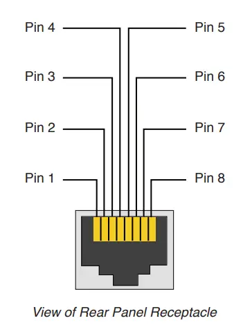
| Pin | Function | Usage |
| 1 | +Vref | CSR-V |
| 2 | Vol Ctrl | CSR-V |
| 3 | NC | none |
| 4 | Gnd | Serial |
| 5 | Rx | Serial |
| 6 | Tx | Serial |
| 7 | NC | none |
| 8 | Gnd | CSR-V |
List of Serial Commands
| Command | Action | Comment |
| mu 0 0 | mute channel 1 | |
| mu 0 1 | unmute channel 1 | |
| mu 1 0 | mute channel 2 | |
| mu 1 1 | unmute channel 2 | |
| sl 0 | sleep | |
| sl 1 | wake up | |
| vs 0 x | set channel 1 volume to x | x is an integer from 0 to 37 (refer to table on p. 21) |
| vs 1 x | set channel 2 volume to x | x is an integer from 0 to 37 (refer to table on p. 21) |
| vg 0 | get channel 1 current volume value | returns an integer between 0 and 37 |
| vg 1 | get channel 2 current volume value | returns an integer between 0 and 37 |
|
vr |
get machine information | Returns output such as:
CPU version: 04000008 Where Model: CSA1300 Sleep State: k k: 0=sleep, 1=wake ch1 vol=m, ch2 vol=n m, n: 0, 1…. 36, 37 ch1 mute=y, ch2 mute=z y, z: 0=muted, 1= unmuted |
Serial Communication Settings
BAUD rate 115200
- 8-bit data
- 1-bit start
- 1-bit stop
- No parity
Volume Level Settings
| Integer | Volume Level (Attenuation) |
| 0 | 0dB |
| 1 | -1.65dB |
| 2 | -3.3dB |
| 3 | -4.9dB |
| 4 | -6.6dB |
| 5 | -8.25dB |
| 6 | -9.9dB |
| 7 | -11.55dB |
| 8 | -13.2dB |
| 9 | -14.85dB |
| 10 | -16.5dB |
| 11 | -18.15dB |
| 12 | -19.8dB |
| 13 | -21.45dB |
| 14 | -23.1dB |
| 15 | -24.75dB |
| 16 | -26.4dB |
| 17 | -28.05dB |
| 18 | -29.7dB |
| 19 | -31.35dB |
| 20 | -33dB |
| 21 | -34.65dB |
| 22 | -36.3dB |
| 23 | -37.95dB |
| 24 | -39.6dB |
| 25 | -41.25dB |
| 26 | -42.9dB |
| 27 | -44.55dB |
| 28 | -46.2dB |
| 29 | -47.85dB |
| 30 | -49.5dB |
| 31 | -51.1dB |
| 32 | -52.8dB |
| 33 | -54.45dB |
| 34 | -56.1dB |
| 35 | -57.75dB |
| 36 | -59.4dB |
| 37 | -61.05dB |
Appendix C: Contact Information
For additional information, please consult JBL Professional Customer Service, your system installer or retailer.
On The World Wide Web: www.jblcommercialproducts.com
Professional Contacts, Outside the USA:
Contact the JBL Professional Distributor in your area. A complete list of JBL Professional international distributors is provided at our U.S.A. Website: www.jblpro.com
JBL Commercial 10653 South Riverfront Parkway Suite 300 South Jordan, Utah 84095
Part Number:5050610 Issue: 12/16
FAQS
Will this power 10 speakers on one line?
Though the other answer is theoretically correct, you should only utilize 80% of the available output power. In your case, this would mean 40 watts x 80%=32watts \ 10 speakers=3.2 watts.
Does it have a Bluetooth connection?
No.
Power cord included? Manual? What else comes in the parts box?
I purchased the 2 channel amp version, but as I recall, it included a power cable, manual and rack mount ears as well.
Does the amplifier come with the two green 2 Euro-block connectors for the back panel connections?
Yes
Can we bridge this amp?
Buy a bigger amp.
We replaced a Paso dms3120 with this jbl csa1300, utilizing the same connections we no longer can page through the store. does anyone do paging with this?
You will need a mixer to do paging. The Paso might have had a built-in mixer
Can I hook a Paging Mic directly to the unit?
Only if the mic is powered. The unit requires a line-level input. A cheap mixer will do the trick..
Does this produce 300 watts per channel or all together?
300 watts all together
Will this power 10 speakers on one line?
Though the other answer is theoretically correct, you should only utilize 80% of the available output power. In your case this would mean 40 watts x 80%=32watts \ 10 speakers=3.2 watts.
Does it have a Bluetooth connection?
No
Is JBL Professional CSA 1300 Z Commercial Series Single Channel 300 Watt Power Amplifier available and ready for delivery in Lome, Sokode, Kpalime, Atakpame, and Sansanne-Mango in Togo?
desert art ships the JBL Professional CSA 1300 Z Commercial Series Single Channel 300 Watt Power Amplifier to Lome, Sokode, Kpalime, Atakpame, Sansanne-Mango, and more cities in Togo. Get unlimited free shipping in 164+ countries with desert art Plus membership. We can deliver the JBL Professional CSA 1300 Z Commercial Series Single Channel 300 Watt Power Amplifier speedily without the hassle of shipping, customs or duties.
Does the desert cart have 100% authentic JBL Professional CSA 1300 Z Commercial Series Single Channel 300 Watt Power Amplifier online?
desert art buys JBL Professional CSA 1300 Z Commercial Series Single Channel 300 Watt Power Amplifier directly from authorized agents and verifies the authenticity of all the products. We have a dedicated team who specializes in quality control and efficient delivery. We also provide a free 14 days return policy along with a 24/7 customer support experience.
Is it safe to buy JBL Professional CSA 1300 Z Commercial Series Single Channel 300 Watt Power Amplifier on desert art?
Yes, it is absolutely safe to buy JBL Professional CSA 1300 Z Commercial Series Single Channel 300 Watt Power Amplifier from desert art, which is a 100% legitimate site operating in 164 countries. Since 2014, desert art has been delivering a wide range of products to customers and fulfilling their desires. You will find several positive reviews by desertcart customers on portals like Trustpilot, etc. The website uses an HTTPS system to safeguard all customers and protect financial details and transactions done online. The company uses the latest upgraded technologies and software systems to ensure a fair and safe shopping experience for all customers. Your details are highly secure and guarded by the company using encryption and other latest software and technologies.


