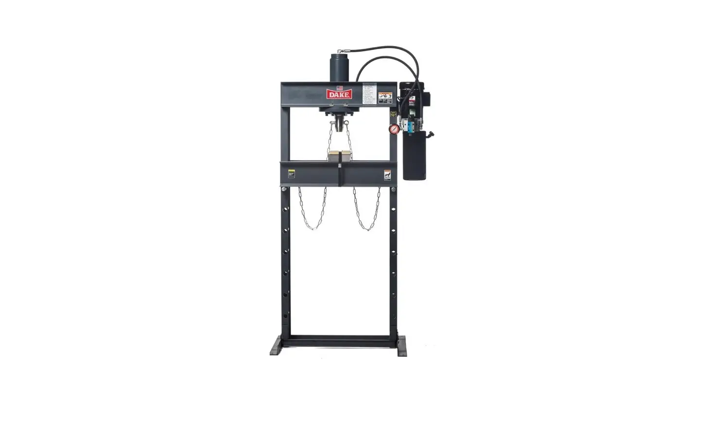
Force 25DA Dake Single Phase Dura-Press Instruction Manual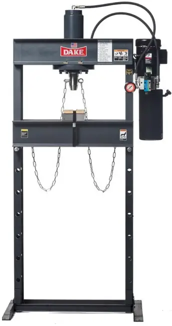
SAFEGUARDING THE POINT OF OPERATION
ANSI B11.2 – Hydraulic Power Presses – Safety Requirements for Construction, Care, and Use
It is important that Dake press users have a clear understanding of their responsibility involving the care and use of their Dake hydraulic press, including point-of-operation safe guards. Dake strongly recommends that Dake press users obtain a copy of the current American National Standard Institute (ANSI) B11.2 standard, for a more complete understanding of their responsibilities.
ANSI B11.2 states the following, relative to point of operation safeguarding:
“Normally, only the employer (press user) can determine the requirements of the press productions system components, including the dies and methods for feeding. Therefore, the employer is ultimately responsible to designate and provide the point-of-operation safeguarding system.”
The standard also discusses additional responsibilities of the employer. Some of the key responsibilities are:
- The employer is responsible for the safety, use, and care of the hydraulic power press production system.
- The employer is responsible to consider the sources of hazards for all tasks to be implemented on the hydraulic power press production system.
- The employer is required to eliminate, or control identified hazards in the scope of their work activity.
- The employer is responsible for the training of personnel, caring for, inspecting, maintaining, and operating hydraulic press production systems to ensure their competence.
- The employer is responsible to provide and ensure that point-of-operation safeguarding is used,checked, maintained, and where applicable, adjusted on every production operation performed on a press production system.
A complete and current copy of the ANSI B.11.2 standard can be obtained by contacting the following:
SPECIFICATIONS
| Model | Force 25DA |
| Number | 909215 |
| Capacity | 25 tons |
| Horse Power | 1 HP |
| Voltage | 110V Single Phase |
| Ram Travel | 10” |
| Pressing Speed | 10 ipm |
| Width between uprights | 28” |
| Max. ram to table | 44” |
| Height | 88” |
| Base | 30” x 38” |
| Weight | 570 lbs. |
In the spac provided record the serial number and model number of the machine. This information is only found on the black and gold Dake tag shown below. If contacting Dake this information must be provided to assist in identifying the specific machine.
| Serial No. | |
| Model No. | |
| Install Date: |
![]() This is the safety alert symbol. When you see this symbol on your press be alert to the potential for personal injury.
This is the safety alert symbol. When you see this symbol on your press be alert to the potential for personal injury.
Employer is responsible to perform a hazard/PPE assessment before work activity.
Label Placement View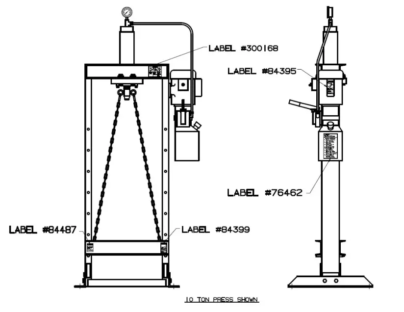
![]() Warning
Warning
Establish Solid footing to prevent falls.
Keep hand away from point of operation. Read instructions.
Guard workpiece to prevent projectiles from reaching operator.Wear eye protrction.
SAFETY INSTRUCTIONS
LOCKOUT PROCEDURE
- Announce lockout to other employees.
- Turn power off at main panel.
- Lockout power in off position.
- Put key in pocket.
- Clear machine of all personnel.
- Test lockout by hitting run button.
- Block, chain or release stored energy sources.
- Clear machine of personnel before restarting machine.
![]() Warning
Warning
Keep Finger out of pin holes.
![]() Warning
Warning
Press frame work is not designed to withstand pulling force.
![]() Danger
Danger
High voltage. Can cause severe injury or death. Service by authorized personnel only.
Use lockout.
![]() Caution
Caution
ALL pins must be inserted before applying any pressure Read instructions.
Follow recommended precautions and safe operating practices. It is important that the operator understand all safety instruction listed below in order to prevent damage to themselves, others, or the machine:\
- Carefully read all the safety messages in this manual and on your press safety labels. Keep safety labels in good condition. Replace missing or damaged safety labels.
- Do not alter this press from its original design.
- Do not make repairs or adjustments to any hydraulic system unless you are competent orworking under competent supervision.
- Only use Dake original parts.
- This machine is intended to be operated by one person. This person should be conscious of the ram movement not only for themselves but also for persons in the immediate area of the machine.
- This press is not intended for pulling operations. Personal injury or machine damage can result.
SET UP
PRESS PLACEMENT
- The press needs to be placed so that it has a safety perimeter of 2-1/2 feet on all sides from any other objects or machines.
- Press should be placed on level floor with base angles touching the floor at all points. Use shims where necessary.
FILLING THE PRESS WITH OIL
Fill the reservoir with DTE 24 Mobil hydraulic oil or equivalent.
a. 25DA holds 2 gallons of oil. Make sure the oil is new and be cautious no contaminants get in while filling the reservoir.
b. Oil should be changed about once a year.
WIRING INSTRUCTIONS
![]() WARNING: A licensed qualified electrician that follows all state and local laws must wire and install electrics on this press.
WARNING: A licensed qualified electrician that follows all state and local laws must wire and install electrics on this press.
110 Volt 19.4 AMPS
For 110 volts this machine is ready to plug in. The machine can be wired 220-volt single phase. Always follow the wiring diagram provided in the moor cover when converting to 220-volt single phase. A cord and plug that is rated for a specific voltage and amperage must be used. This rating can be found on the motor.
220 Volt Single Phase
The press new is shipped out as a 110-volt machine. If wiring must be changed to suit 220-volt single phase.
- The leads on the motor must be changed to fit 220-volt, 17.2 amps, follow the diagram onthe motor.
- Install plug and wire that fits the rating on the motor, the plug and wire must be rated for the voltage and amperage listed on the motor.
OPERATION
BEFORE FIRST TIME OPERATION
- Make sure the reservoir is filled with 3 gallons of Mobil DTE 24 hydraulic fluid or equivalent.
- Turn the on/off power (toggle) switch to the “on” position (up).
- Move the control lever down, this will advance the ram in the downward position.
- Release the control lever and the ram will stop all movement.
- Move the control lever to the up position and the ram with move up.
- When the press is new be sure to move the ram up and down to work out any air that may be in the system.
![]() WARNING: When using the control lever in pressing operations or to return the ram stop applying pressure once the handle reaches its positive stop. Applying additional force on the lever does not increase ram speed and will lead to premature damage of the valve.
WARNING: When using the control lever in pressing operations or to return the ram stop applying pressure once the handle reaches its positive stop. Applying additional force on the lever does not increase ram speed and will lead to premature damage of the valve.
TROUBLESHOOTING
| SYMPTOM | CAUSE | SOLUTION |
| Ram runs jerky while moving up and down | Air is in the system | This press has a self- bleeding system, continue to run the ram up and down approximately 15 times. |
| Machine will not build desired pressure | Relief valve needs to be reset | Remove octane cap from back of manifold and adjust set screw to correct pressure. WARNING: Do not exceed 2413 PSI |
| Pins are shearing or bending | Relief valve needs to be reset | Remove octane cap from back of manifold and adjust set screw to correct pressure. WARNING: Do not exceed 2413 PSI |
| Oil Leaks around the ram | Cylinder seals are worn or damaged | Replace cylinder seals |
| Oil leaks around holes other than the ram | Bolts need to be tightened | Tighten bolts around the ram |
| Ram will not extend the full 10 inches | Oil level is too low | Re-fill the reservoir with oil |
| Hydraulic gauge will not read pressure | Hydraulic gauge is bad | Replace hydraulic gauge |
| Motor will not start | No power to press | Double check electrical cord |
| Motor overheats and shut down | Duty cycle time is exceeded | Check the duty cycle time on the motor. (Has no cooling fan, 15-20 minutes) |
| Extension cord is being used | Extension cord will lower the APMS and will cause overheating of the motor.Remove cord. |
MAINTENANCE
LUBRICATION
Keep all working parts of press well oiled for easier operation. Also, keep a light film of oil over the entire surface of the ram to prevent rust.
HYDRAULIC LINES AND FITTINGS
If there is ever any maintenance done with the hydraulic components below is how to reinstall all components.
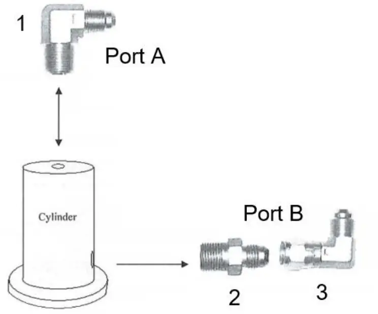
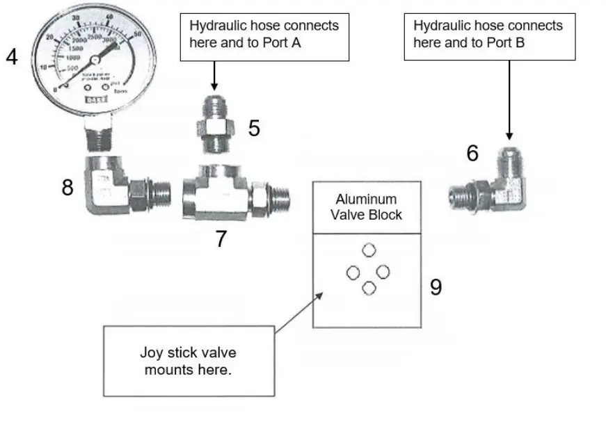
![]()
WARNING! Be sure all fittings and bolts are tight. Do not over tighten fittings or bolts.
If your power unit looks like this use the numbers below for ordering.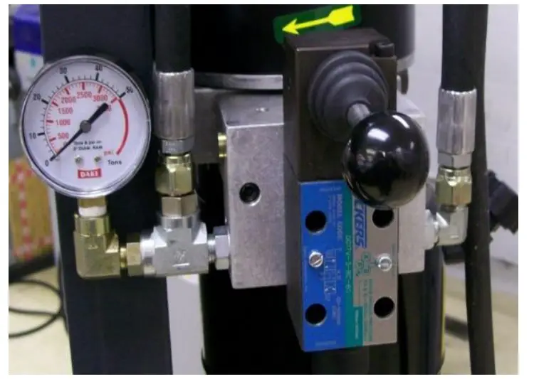
| Item | Part No. |
| 1 | 72050 |
| 2 | 73425 |
| 3 | 72047 |
| 4 | 302938 |
| 5 | 69671 |
| 6 | 72402 |
| 7 | 302183 |
| 8 | 302061 |
| 9 | 302224 |
| Breather Vent & Elbow | 300267 |
| Reservoir | 300269 |
| Power Unit | 300265PU |
| Hose & Valve kit | 300265KIT |
| 4-Way Valve | 301864 |
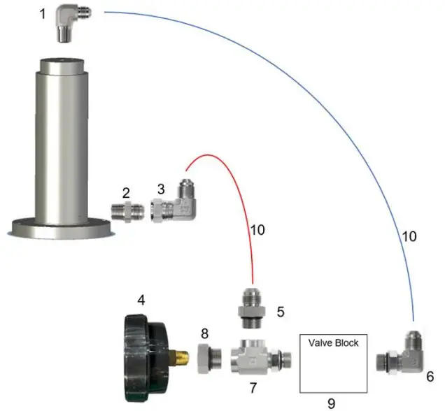
If your power unit looks like this use the numbers below for ordering.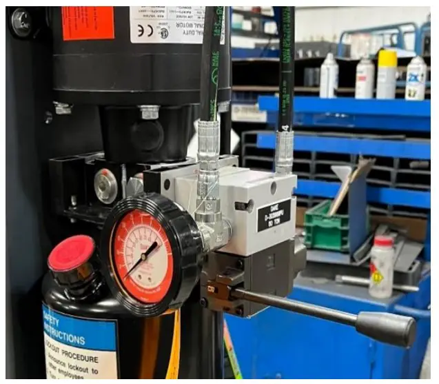
| Item | Description | Part No. | Qty |
| 1 | Tube Fitting, Elbow (3/8 x 3/8 NPTF) | 72050 | 1 |
| 2 | Tube Fitting, Straight (3/8 x 3/8 NPTF) | 73425 | 1 |
| 3 | Swivel Nut Elbow (3/8) | 72047 | 1 |
| 4 | Gauge | 302938 | 1 |
| 5 | Tube Fitting, Straight (SAE 6) | 69671 | 1 |
| 6 | Tube Fitting, Elbow (SAE 3 Male x 1/4 NPT Female) | 302061 | 1 |
| 7 | Branch Tee | 302183 | 1 |
| 8 | Adapter (3/8” SAE Male x 1/4 NPT Female) | 303124 | 1 |
| 9 | Manifold | 303946 | 1 |
| 10 | Hose (1/4 x 54” long) | 303948 | 2 |
| – | Reservoir | 304097 | 1 |
| KIT | Hose & Fittings KitItems 1-3,5-8,10 (x2) Gauge sold separately. | 303975KIT | – |
| PU | Power unit, including manifold and valve | 303975PU |
EXPLODED VIEWS & PART
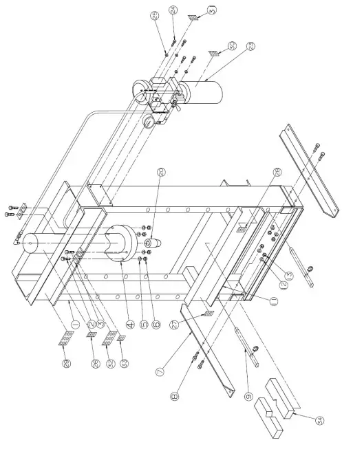
| Item | Part Description | Part No. | Qty |
| 1 | Frame | 86684 | 1 |
| 2 | Screw (1/2″-13 x 2-3/4″) | 43355 | 4 |
| 3 | Channel Washer (1/2”) | 43657 | 4 |
| 4 | Work-head Assembly | 716640 | 1 |
| 5 | Lock Washer (1/2”) | 43647 | 4 |
| 6 | Hex Nut (1/2”-13) | 43916 | 4 |
| 7 | Base Angle | 978 | 2 |
| 8 | 1/2″ – 13 x 1-1/2” Grade 5 | 43349 | 4 |
| 9 | Table Pin | 85407 | 2 |
| 11 | Table Channel | 86682 | 1 |
| 12 | Lock Washer (1/2”) | 43644 | 4 |
| 13 | Hex Nut (1/2”-13) | 43916 | 4 |
| 20 | Nose Piece | 86683 | 1 |
| 23 | Hydraulic Power Unit | See pgs. 11-12 | 1 |
| 24 | Screw (5/16″ – 18NC x 1″) | 43315 | 4 |
| 25 | Flat Washer (5/16”) | 43632 | 4 |
| 27 | Warning Label | 84487 | 1 |
| 28 | Warning Label | 84399 | 1 |
| 29 | 3-IN-1 Warning Label | 300168 | 1 |
| 30 | Safety Instructions | 76462 | 1 |
| 31 | Warning Label | 84395 | 1 |
| 32 | DAKE Name Plate | 81002 | 1 |
| 33 | Made In USA Plate | 76936 | 1 |
| 34 | Table Plates | 85508 | 2 |
| Parts not illustrated | |||
| Item | Description | Part No. | Qty |
| Breather Vent & Elbow | Reservoir fill port | 300267 | 1 |
| Eyebolts | 300284 | 2 | |
| Triangular Snap Hooks | 300285 | 4 | |
| Coil Chain | 78477 | 2 | |
| Gauge | Tons/PSI | 302938 | 1 |
| Valve Kit | Fittings, hoses, valve, manifold, bolts, & O-rings | See pgs. 11-12 | 1 |
| Optional Check Valve | 302071 | 1 | |
| Optional Remote Relief Valve | 290-3625 PSI or 20-250 Bar | 301949 | 1 |
| Optional Relief Valve | 43.5-435 PSI or 3-30 Bar | 302197 | 1 |
| Optional Flow Control Valve | 302796 | 1 | |
| Bolts SHC #10-24 x 1-3/4” | Mounting bolts for valve only | 43403 | 4 |
| Bolts SHC #10-24 x 2-3/4” | Mounting bolts for valve, relief valve, or check valve | 76749 | 4 |
| Bolts SHC #10-24 x 4-1/2” | Mounting bolts for valve, relief valve, or check valve | 302221 | 4 |
| Bolts #10-24 x 7-3/4” | For 4-Way, Relief, Check & Flow Control Valves | 3040 | 4 |
WOKRHEAD DIAGRAM
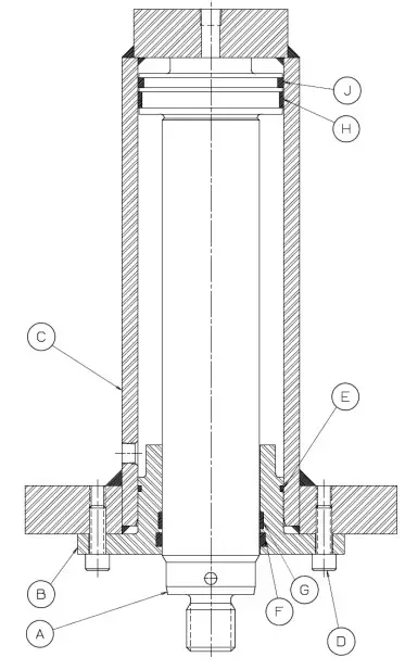
| Item | Description | Part # |
| A | Piston | 86463 |
| B | Cylinder Flange | 86462 |
| C | Cylinder | 86461 |
| D | Socket Head Cap Screw | 43471 |
| E | O-Ring | 79881 |
| F | Seal | 79880 |
| G | Wear Ring | 78486 |
| H | Wear Ring | 79840 |
| J | O-Ring Seal | 79882 |
| – | Workhead Assembly | 716640 |
ORDERING INFORMATION
Parts are available for direct purchase from Dake or through a distributor. When placing a parts vorder, you will need to provide the part number, name of part, and model number. All parts shipped F.O.B. Factory in Grand Haven, MI.
DAKE STANDARD LIMITED WARRANTY
Finished Machines
Dake warrants to the original purchaser the finished machine manufactured or distributed by it to be free from defects in material and workmanship under normal use and service within 1 year (12 months) from the delivery date to the end user.
Parts
Dake warrants to the original purchaser the component part manufactured or distributed by it to be free from defects in material and workmanship under normal use and service within 30 days from the delivery date to the end user.
The standard limited warranty includes the replacement of the defective component part at no cost to the end user.
Sale of Service (Repairs)
Dake warrants to the original purchaser the component part repaired by Dake Corporation at the manufacturing facility to be free from defects in material and workmanship under normal use and service within 90 days from the return date to the end user, as it pertains to the repair work completed. The standard limited warranty includes repair of the defective component part, at no cost to the end user.
Warranty Process
Warranty Process Subject to the conditions hereinafter set forth, the manufacturer will repair or replace any portion of the product that proves defective in materials or workmanship. The manufacturer retains the sole right and option, after inspection, to determine whether to repair or replace defective equipment, parts or components. The manufacturer will assume ownership of any defective parts replaced under this warranty.
All requested warranty claims must be communicated to the distributor or representative responsible for the sale. Once communication has been initiated, Dake Customer Service must be contacted for approval:
Phone: (800) 937-3253
Email: [email protected]
When contacting Dake, please have the following information readily available:
- Model #
- Serial #
- Sales Order #
Purchasers who notify Dake within the warranty period will be issued a Case number and/or a Return Material Authorization (RMA) number. If the item is to be returned per Dake’s request, the RMA number must be clearly written on the exterior packaging. Any item shipped to Dake without an RMA will not be processed.
Warranty Exceptions:
The following conditions are not applicable to the standard limited warranty:
(a) Part installation or machine service was not completed by a certified professional, and is not in accordance with applicable local codes, ordinances and good trade practices.
(b) Defects or malfunctions resulting from improper installation or failure to operate or maintain the unit in accordance with the printed instructions provided.
(c) Defects or malfunctions resulting from abuse, accident, neglect or damage outside of prepaid freight terms.
(d) Normal maintenance service or preventative maintenance, and the parts used in connection with such service.
(e) Units and parts which have been altered or repaired, other than by the manufacturer or as specifically authorized by the manufacturer.
(f) Alterations made to the machine that were not previously approved by the manufacturer, or that are used for purposes other than the original design of the machine.
RETURN & REFUND POLICY
Thank you for purchasing from Dake! If you are not entirely satisfied with your purchase, we are here to help.
Returns
All Dake manufactured / distributed machines, parts and couplings include a 30-day return option. These policies are valid from the date of final shipment to the end user.
To be eligible for a return, the item must be unused and in the same condition as received.
All requested warranty claims must be communicated to the distributor or representative responsible for the sale. Once communication has been initiated, Dake Customer Service must be contacted for approval:
Phone: (800) 937-3253
Email: [email protected]
Once the return request has been approved by Customer Service, a representative will supply a Return Material Authorization (RMA) number. The returned item must have the provided RMA number clearly marked on the outside packaging. Any item received without an RMA number clearly visible on the packaging will not be processed. An RMA number can only be provided by the Dake Customer Service team and must be obtained prior to the return shipment.
Refunds
Once the item has been received and inspected for damages, a representative will notify the requestor referencing the provided RMA number.
If the return is approved, a refund will be issued to the original method of payment, less a 20% restocking fee. The restocking fee may be waived if an order is placed at the time of return with like-value= merchandise.
Transportation costs are the responsibility of the end user and will not be credited upon return approval.
Any item that is returned after the initial 30 days or has excessive/obvious use will not be considered for a full refund.
Costumer Support
Dake Corporation
1809 Industrial Park Dr
Grand Haven, MI 49417
www.dakecorp.com