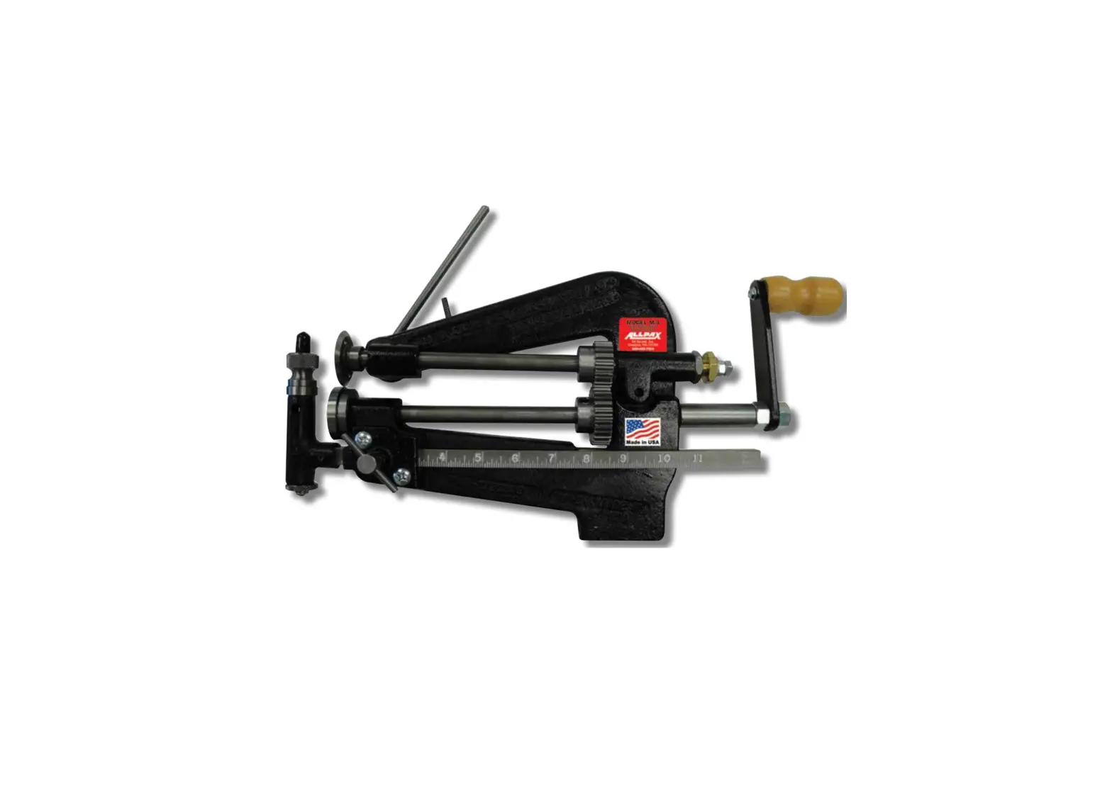
ALLPAX M3 AX7000 Rotary-Style Gasket Cutter
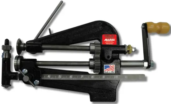
Model M3
INTRODUCTION
Congratulations! You are the owner of the finest rotary-style gasket cutter in the world. Originally developed and patented in the 1930’s, the M3 Rotary-Style Gasket Cutter is ideal for the custom fabrication of ring and flange gaskets. Thousands are in use everyday in a wide range of industries including petrochemical plants, shipbuilding yards, power plants, breweries, pulp and paper plants, refrigerated facilities, and oil refineries. Easy to operate and virtually maintenance-free, the M3 Rotary-Style Gasket Cutter will cut perfect gaskets and provide trouble-free operation for years to come.
MODEL M3 SPECIFICATIONS
| Weight: | 15 pounds |
| Configuration: | Recommended for fixed or mobile operation. |
| Mounting: | Vice mount, or clamp to angle iron |
| Throat: | 7” |
| Cutting Diameters: | 2”ID to 22”OD with standard scale 22”ID to 42”OD with optional scale bar (not included) 42”ID to 62”OD with optional scale bar (not included) |
| Gasket Width: | 1/4” to 7” |
| Gasket Thickness (Max): | 1/4” (See table for maximum thickness by mate |
| Cutter Set Installed | Cutter set (top & bottom) for non-metallic gaskets |
MODEL M3
Maximum Recommended Material Thickness (Inches)
| GASKET MATERIAL | THICKNESS |
| Asbestos | 0.125 |
| Cardboard (Flat) | 0.250 |
| Cloth Insert | 0.188 |
| Cork | 0.188 |
| Fiber | 0.188 |
| Kevlar | 0.010 |
| Rubber | 0.188 |
| Teflon | 0.125 |
ASSEMBLY
Carefully unpack the unit. Remove the protective tape around the top cutting disc being careful of the razor sharp edge. The Model M3 comes fully assembled and pre-adjusted at the factory.
MOUNTING THE UNIT
(Figure 1) Model M3 mounts to any workbench equipped with a vise, or to a vertical flange with the use of c-clamps (not included)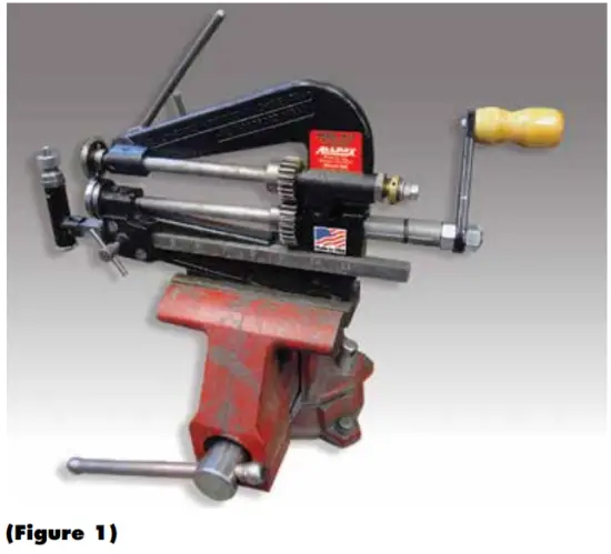
(Figure 2) Proper hand crank rotation as viewed from side.
NOTE: In the instructions that follow, turning the hand crank in the direction of the arrow above is considered clockwise.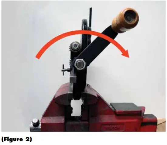
OPERATING THE UNIT
Model M3 is equipped with a set of cutting discs for non-metallic gasket materials. With the exception of very thin metallic materials, cutting metallic gaskets is generally not recommended.
Select the sheet gasket material to be cut. Measure the material and cut into a rough square making sure that the shortest side measures larger than the outside diameter (OD) of the gasket to be cut. Trim the corners if necessary.
Punch 11/32″ guide hole (#13 punch) in the approximate center of the trimmed gasket material.
NOTE: Punching the exact diameter guide hole ensures that the gasket material stays centered and that the cutter tracks properly.
(Figure 3) Loosen the scale bar T-screw and slide the scale bar to the desired OD setting. Hand tighten the T-screw.
NOTE: Markings on the scale bar designate radius, not diameter.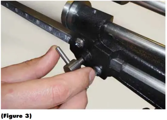
(Figure 4) Disengage the top cutting disc by rotating the cutter disc lever counter-clockwise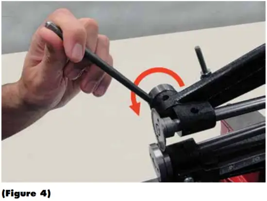
(Figure 5) Unscrew and remove the scale bar knurled nut from the scale bar assembly. Using the guide hole, position the gasket material onto the threaded scale bar spindle. Screw the knurled nut back onto the spindle to firmly secure the material. Hand tighten.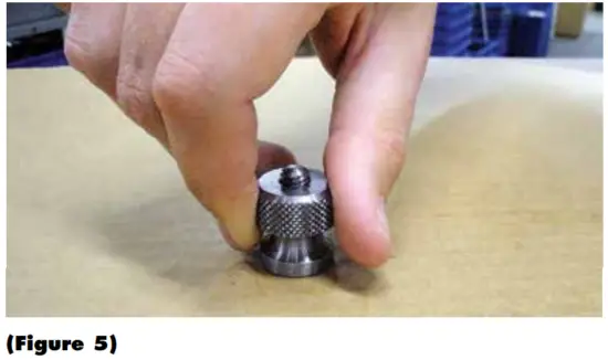
(Figure 6) To cut the OD, engage the top cutting disc by rotating the cutting disc lever clockwise. The top cutting disc should now penetrate the gasket material and is now in the proper position for cutting.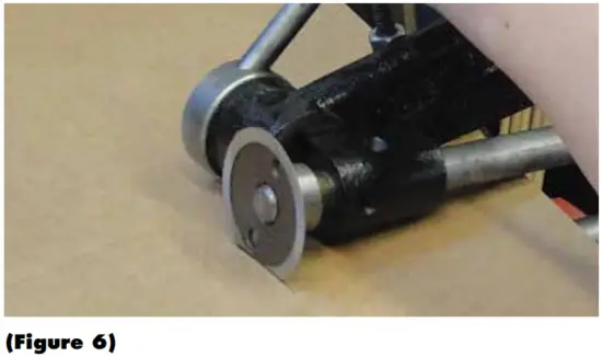
(Figure 7) Turn the hand crank clockwise. Simultaneously, with the other hand, maintain a constant downward pressure on the cutting disc lever. As the cutting discs rotate, the gasket material will be drawn towards the cutting discs initiating the cutting process. Continue cranking until the entire OD of the gasket material has been cut. Disengage the top cutting disc. Discard unwanted material.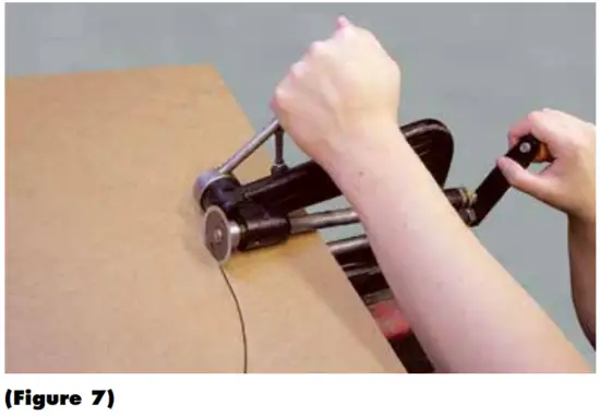
(Figure 8) To cut the inner diameter (ID), loosen the scale bar T-screw, and slide the scale bar to the desired setting. Hand tighten the scale bar T-screw. Engage the top cutting disc. Turn the hand crank, simultaneously maintaining downwards pressure on the cutting disc lever as before. Continue cranking until the entire ID of the gasket material has been cut. Disengage the top cutting disc and remove newly cut gasket. Unscrew and remove knurled nut from spindle. Discard unwanted material.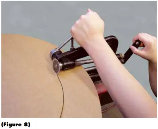
(Figure 9) To cut irregular shaped gaskets, mark the shape desired on the gasket material with a pencil or pen. Loosen the scale bar T-screw. Remove the scale bar, and manually feed the material through the cutters while operating the unit in the same manner as above. An additional set of hands may be needed to guide material.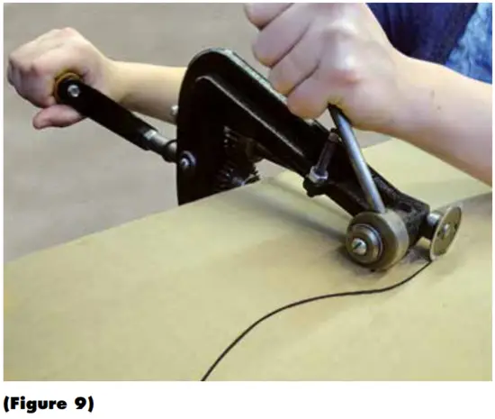
REPLACING THE CUTTING DISCS
The Model M3 incorporates a set of cutting discs that can be replaced as they wear. Both discs are held in place via threads.
NOTE: The top cutting disc incorporates a left-hand thread and the bottom disc incorporates a right-hand thread.
(Figure 10) To replace the top cutting disc, first remove the scale bar assembly. Disengage the top cutting disc. Insert the spanner wrench (included) into the two holes on the disc. Grip the spanner wrench firmly. Loosen the disc by turning the hand crank counter-clockwise. Loosening the thread may require a firm strike to the hand crank. Screw a new cutting disc into place using the spanner wrench. Tighten by turning the hand crank clockwise.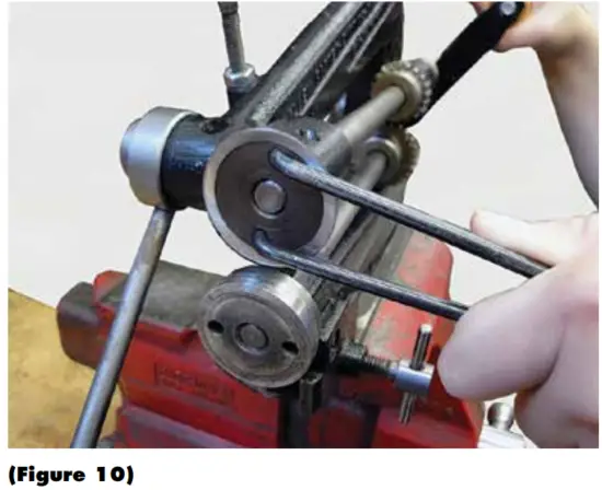
(Figure 11) To replace the bottom cutting disc, first remove the scale bar assembly. Disengage the top cutting disc. Insert the spanner wrench into the two holes on the bottom disc. Grip the spanner wrench firmly. Loosen the disc by turning the hand crank counter-clockwise.
Loosening the thread may require a firm strike to the hand crank. Screw a new cutting disk into place using the spanner wrench. Tighten by turning the hand crank clockwise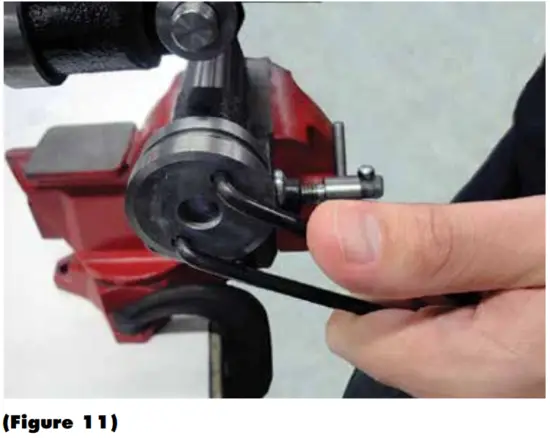
(Figure 12) Sharpen by holding a small, hand sharpening stone to bevel side of the cutting disc. Slowly turn the hand crank. Then hold the stone to the flat face to remove rolled edges or burrs.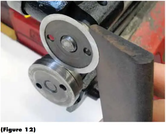
NOTE: The bottom cutting disc is not designed to be sharpened.
CUTTER ADJUSTMENTS
The positions of the cutting discs are pre-set at the factory. However, over time, as cutting discs wear and/or are replaced, adjustments may need to be made to maintain proper operation.
Check the cutting discs to make sure that the cutting edges are sharp, have no nicks or dings, and are concentric. Replace if necessary. Ensure that the discs are tight on their respective shafts by tightening with the spanner wrench. To adjust the cutter refer to the CUTTER ADJUSTMENT DIAGRAMS on page 7.
Note: Proper cutter adjustment must proceed in the following order: Top Shaft Assembly End-Play, Clearance, Depth.
Removing Top Shaft Assembly End-Play
Disengage the top cutting disc (A) by rotating the cutting disc lever (H) counter-clockwise. Using 7/8″ wrench, loosen jam nut (C). Preset thrust bearing (D) to a space of 3/16″ with 7/8″ wrench. Tighten the jam nut against thrust bearing housing (G).
(Figure 13) Remove top shaft assembly end-play by unscrewing the outer hex-nut (F) with 7/16″ wrench and adjusting the inner hexnut (E) in, or out. Once end-play is removed (top shaft assembly will not slide back and forth), lock the inner hex-nut in position. Hold the inner hex-nut with a wrench and tighten the outer hex-nut snug against the inner hex-nut, being careful not to change the position of the inner hex-nut. Double check that end-play has been removed. Crank cutter handle to make sure the top shaft assembly has not been adjusted too tight that it rotates with just slight resistance.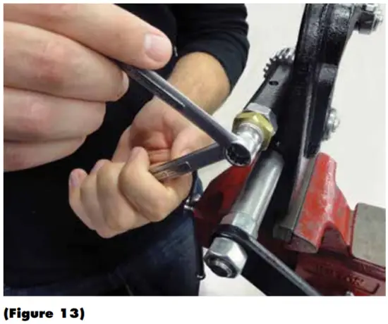
Clearance Adjustment (x axis)
First, set the initial clearance between the bottom cutting disc (B) and top cutting disc (A). Loosen the jam nut until the thrust bearing rotates freely. Engage the top cutting disc by slowly rotating the cutting disc lever clockwise, making sure that the top cutting disc lines up with the slot adjacent to the bottom cutting disc. Adjust the thrust bearing in or out as necessary to ensure this alignment.
(Figure 14) The final clearance can now be set by gently tightening the thrust bearing until the side of the top cutting disc just contacts the side of the bottom cutting disc, then backing off slightly. Tighten the jam nut against thrust bearing housing.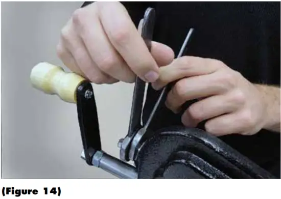
Note: When making the clearance adjustment, make sure the outermost edge (diameter) of the top cutting disc does not interfere with the bottom cutting disc when engaging cutting disc lever, or damage will occur to the top cutting disc edge.
The correct clearance adjustment positions the discs close enough such that standard copy paper can be cut cleanly by the unit.
Depth Adjustment (y axis)
(Figure 15) The depth of cut is adjusted by screwing the depth adjustment screw (I) in, or out, until 1/32″ depth of cut is achieved. Lock adjustment screw in place with locking nut using 7/16″ wrench.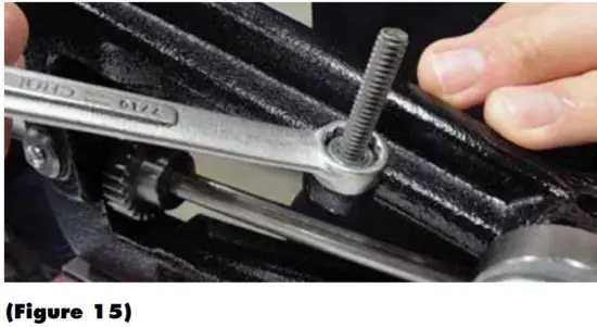
Note: The correct depth adjustment allows the top cutting disc to be fully lowered adjacent to the bottom cutter without mechanical interference.
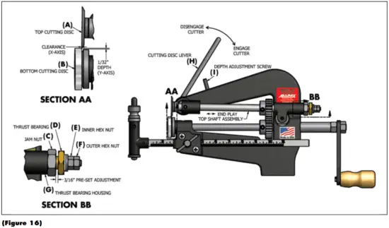
CUTTER ADJUSTMENT DIAGRAMS
GENERAL MAINTENANCE AND LUBRICATION
(Figure 17) The Model M3 is pre-lubricated at the factory. Like any piece of precision machinery, regular cleaning and lubrication of all gears, and moving parts is recommended. Light machine oil should periodically be applied to points A, B, C, D, E and F. Replace worn parts as necessary.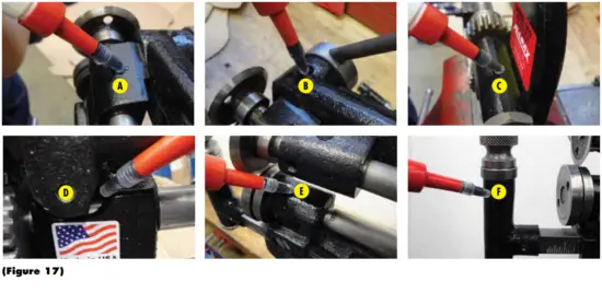
REPLACEMENT PARTS
M3 PARTS (AX7000) | ||
| PRODUCT | PART # | DESCRIPTION |
 | AX1400 | Top Cutting Disc for Non-Metallic Gaskets (M3 & SM4) |
 | AX1401 | Bottom Cutting Disc for Non-Metallic Gaskets (M3) |
 | AX1402 | Cutter Set for Non-Metallic Gaskets (M3) |
 | AX1410 | 2″- 22″ Standard Scale Bar (M3) |
| AX1411 | 22″- 42″ Medium Scale Bar (M3) | |
| AX1412 | 42″- 62″ Long Scale Bar (M3) | |
 | AX1413 | Scale Bar Knurled Nut (M3) |
 | AX1414 | Scale Bar Spindle Assembly (M3) |
 | AX1420 | Thrust Bearing Housing (M3) |
 | AX1421 | Thrust Bearing (M3) |
 | AX1422 | Top Shaft Gear (M3) |
 | AX1423 | Top Shaft (M3) |
 | AX1424 | Bottom Shaft Gear (M3) |
 | AX1425 | Bottom Shaft (M3) |
 | AX1426 | Top Cutter Lifter Bearing (M3) |
 | AX1427 | Top Cutter Lifter Cam (M3) |
 | AX1428 | Handle Assembly (M3) |
 | AX1430 | Spanner Wrench (M3) |
 | AX1431 | 11/32″ Hole Punch (M3) |
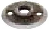
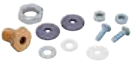 | AX1450 | Top Shaft Hardware Kit. Contains Teflon Washers (2), Beveled Washers (2), Pan Head Screws (2), Thrust Bearing, Hex Jam Nut, Hex Nuts (2), Flat Washer (M3) |
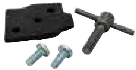 | AX1451 | Scale Bar Plate Kit. Contains Retaining Plate, Pan Head Screws (2), Center Bar Tee Screw (M3) |
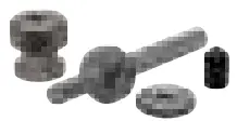
 | AX1452 | Scale Bar Spindle Kit. Contains Center Bar Spindle, Center Bar Knurled Nut, Knurled Washer, Pan Head Screw, Helical Lock Washer, Thread, Cap (M3) |
Replacement parts are available from your local distributor or direct from the factory. Visit our website at www.allpaxcorp.com or call our Customer Service Department for pricing information.
ADDITIONAL TOOLS
Also available from Allpax Gasket Cutter Systems
 | HOLLOW PUNCH TOOL KITS
|
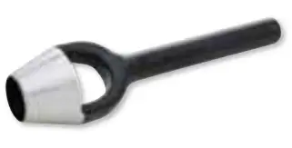
 | HOLLOW PUNCH TOOLS
|
 | ARCH PUNCHES
|
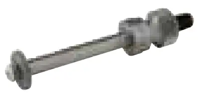
 | POWER PUNCHES
|
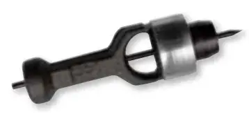
 | DOVE-TAIL PUNCHES
|
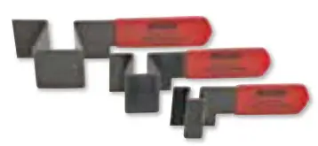
 | DEAD BLOW HAMMERS
|
 | PACKING HOOKS
|
47 Veterans Drive
Chicopee, MA 01022
Phone (413) 594-4400
Toll Free (800) 482-7324
Fax (413) 594-4884
www.guardaircorp.com | [email protected]