![]() INSTRUCTION MANUAL
INSTRUCTION MANUAL
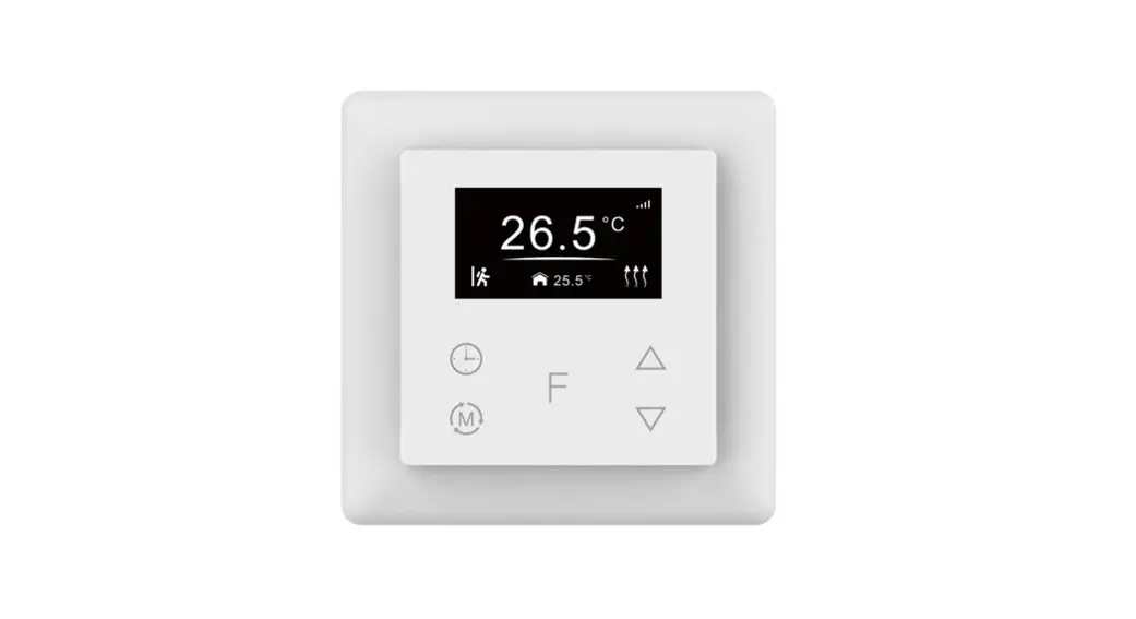
NAMRON THERMOSTAT
TOUCH Z-WAVE 16A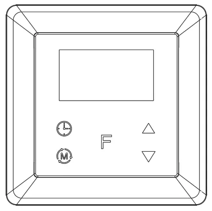
Namron termostat touch Z-Wave 16A
Technical data
| Z-Wave frequency | 868.42MHz (EU) |
| Operation voltage | 220-240V, 50/60Hz |
| Maximum load | 16A |
| Power consumption | <2W |
| Ambient temperature | 0°C to 40°C (during operation) |
| Temperature range | 0°C to 40°C |
| Hysteresis | 0.5°C to 2°C (default 0.5°C) |
| Floor sensor | NTC R25=10K±1%@25°C, B25/50=3950K±1%, (3m included) |
| Floor sensors supported | NTC R25=10K±1%@25°C, B25/50=3950K±1% (factory setting) NTC R25=15K±1%@25°C, B25/50=3950K±1% NTC R25=50K±1%@25°C, B25/50=3950K±1% NTC R25=100K±1%@25°C, B25/50=3950K±1% |
| Control modes | 1. Away 2. Auto 3. Manual 4. Drying 5. Off |
| Control types | Room sensor (factory default) Floor sensor Room + floor sensor This parameter can also be configured through advanced config parameter 10 |
| IP rating | IP21 |
| Relative humidity | 8% to 80% |
| Standard | 60730-1:2016;A1, IEC 60730-2-9:2019;A1 IEC 61000-3-2:2019, 61000-3-3:2013+A1:2019, 60730-1:2016+A1:2019, 60730-2-19:2019+A1:2019+A2:2020, 50663:2017;ETSI 301 489-1V2.2.3,ETSI 301 489-3V2.1.1 ETSI 300 220-1 v3.1.1., ETSI 300 220-2 V3.2.1 RED:2014/53/EU |
| Certificate | Z-Wave plus, CE, RED |
Installation
a.Installation must be done by a qualified electrician.
b.The power supply must be turned off during installation.
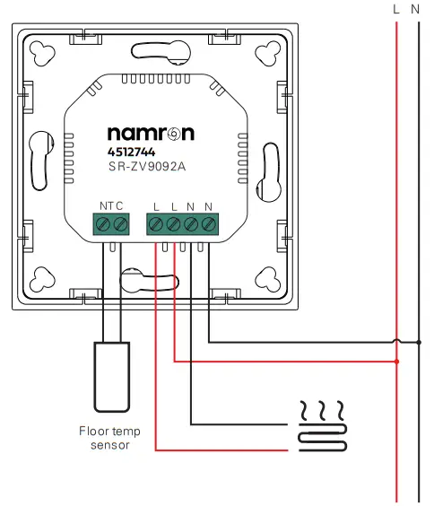
(1) Wiring diagram
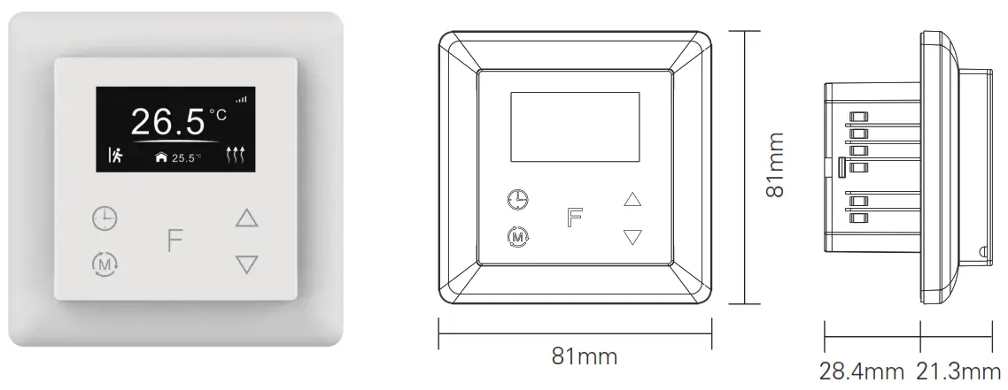
(2) Mounting
a.Remove the display unit and front cover by using a small screwdriver.
b.Insert the wires to the correct terminals as presented in the wiring diagram above. The suggested wire-stripping length is 8-10mm.
c.Fix the thermostat into the connection box by tightening the screws. Make sure that the thermostat is fixed without deformation. Suggested torque is 0.2-0.4Nm (2.0-4.1kgf.cm).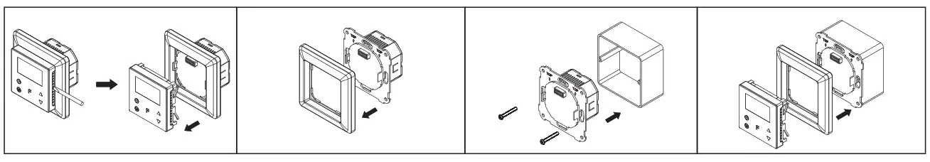
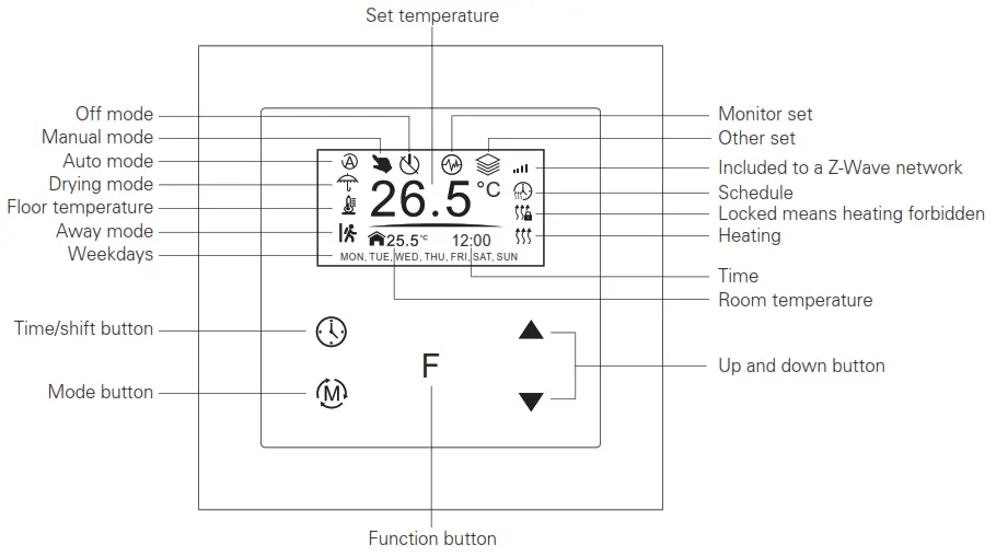
Symbol overview
Settings Menu
Select TIME/DATE on Home Interface to enter into TIME/DATE SET interface as follow:
Enter settings menu (needs to be added)
- Under Home Interface, meanwhile, the device is at OFF mode (Off icon), press and hold up and down buttons at the same time for over 5 seconds to enter Settings Menu.
- Short press moves up and down button to select a settings item, then short press button F to enter selected item.
- Settings menu include Preview menu, Z-Wave settings, Schedule, Monitor settings, Time/Date settings, Other settings
Time Setting
Select TIME/DATE on Home Interface to enter into TIME/DATE SET interface as follow:
Short press button![]() to select the item you would like to modify, then short press up and down buttons to modify the value of the selected item, then short press button F to save and quit, the short pressing button
to select the item you would like to modify, then short press up and down buttons to modify the value of the selected item, then short press button F to save and quit, the short pressing button ![]() only quits without saving.
only quits without saving.
2. Preview interface
On Home Interface, the user can enter into PREVIEW interface, the interface will display some basic configurations, energy consumption, date, floor temperature, etc.
Control Mode
Short press button ![]() on Home Interface to switch operation modes: the icons of Away, Auto, Manual, Drying, Off modes will be displayed alternatively for 3 seconds and last displayed mode will be selected, or just short press F button to select the desired mode when the modes’ icon displayed alternatively. Press and hold
on Home Interface to switch operation modes: the icons of Away, Auto, Manual, Drying, Off modes will be displayed alternatively for 3 seconds and last displayed mode will be selected, or just short press F button to select the desired mode when the modes’ icon displayed alternatively. Press and hold ![]() the button on the Home interface for over 3 seconds to select Away mode directly, then press and hold the
the button on the Home interface for over 3 seconds to select Away mode directly, then press and hold the ![]() button for 3 seconds to quit Away mode.
button for 3 seconds to quit Away mode.
1. Away Mode: the device will control the heating system according to the set temperature within the set period.
Users can set time to leave home and time to go home according to their requirements of, and set how the the device will control the temperature during this period.
1.1. If away mode has already been activated, the end time for away mode is valid, the device will execute Away Mode
Temperature Schedule before the end time.
1.2. If away mode has already been activated, the values of the end time for away mode are set as 0, the device will always execute the current set temperature with no time limitation. The device will consider the mode as anti-freeze mode, the recommended temperature setting is 4-10°C.
2. Auto Mode: the device will control the heating system according to the configured time schedule or Z-Wave protocol
Energy_Save_Heating Setpoint.
2.1. When configuration parameter 8 value is set as 1, the device will control the temperature of energy save mode according to the temperature set by Command Class Energy_Save_Heating Setpoint or set by using the move up and down buttons, the following mentioned schedule will be invalid.
2.2. When configuration parameter 8 value set as 0, the temperature set by Command Class Energy_Save_HeatingSetpoint and set by using the move up and move down buttons will both be invalid, Energy Save Mode will control the temperature according to the following user schedule.
For instance, if the user would like to keep the room temperature at 18C during 18:00-23:00 on every Monday, and keep the room temperature at 20C after 22:30 on every Monday, then the user can set the schedule by himself.
Schedule setting method 1: user can enter into the schedule on Z-Wave Set Interface, the schedule interface is as follows:
Short press button to select “Auto F Schedule”, then short press button Schedule weekly setting interface.
Schedule setting method 2: on Home Interface, meanwhile the device is under Auto Mode, short press button ![]() to enter into Auto Mode Schedule weekly setting interface quickly:
to enter into Auto Mode Schedule weekly setting interface quickly:
On Auto Mode Schedule weekly setting interface, use buttons ![]() and F to enter into schedule setting of a certain week as
and F to enter into schedule setting of a certain week as
follows: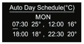 On Auto Day Schedule interface, short press button to select the time or temperature that you would like to modify, then short press move up and down buttons to modify the value, then short press button F to save and quit, the short pressing button only quits without saving.
For each schedule, the latter time should be later than the former time, otherwise saving will fail with the error remind “Time setting error!!!”. The default time schedules are as follows:
| Monday-Friday | 7:30,24C-12:00,20C | Saturday-Sunday | 7:30,24C-12:00,20C |
| 18:00,16C-22:30,18C | 18:00,18C-22:30,18C |
3. Manual Mode: the device will control the heating system according to the current set temperature. The temperature can be set by a move up and move down button on the Home interface, or configured by Z-Wave gateway.
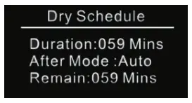
4. Drying Mode: The device will judge the set temperature for heating within a short period of time.
I.e.: in order to dry the water in the bathroom in a short time, the device could be set to quickly heat to dry the floor. Enter the configuration interface is as follow:
Duration: set how long the dry mode should last
After Mode: set the mode after the drying mode ends
Remain: shows the remaining time of the drying mode
For configuration method and modification, please refer to Automatic Mode (Energy Save Mode) Schedule:
5. Off Mode: this mode only enables the device to turn on the heating system when the anti-freezing mode is enabled and the device meets all required conditions, otherwise, the device will not work, meanwhile, the standby interface will only show
room temperature.
| Monitor Set | 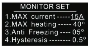 | The function of the monitor set is a real-time monitor of over current, overheat, and freezing. On Home Interface, short press MONITOR SET to enter into monitor set interface as follows: Short press button |
| Over-current Alarm | If the current is over the set value, the relay will be forced off by the device, and the state will be reported to the gateway. The over-current alarm function can be disabled, which can be set directly through the device. Or can be configured through Advance Config parameter 2 by setting the value as 0 to disable the function, please refer to the part “Advance Config”. | |
| Over-heat Alarm | 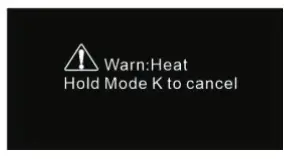 | If room temperature or floor temperature is over the set value, the relay will be forced off by the device, and an overheat alarm will be reported to the associated devices, meanwhile, the buzzer or vibrator will beep 3 times every 10 seconds. The overheat alarm function can be disabled, which can be set directly through the device. Or can be configured through Advance Config parameter 6 by setting the value as 0 to disable the function, please refer to the part “Advance Config”. Overheat alarm interface is as follow: Note: to cancel over the current alarm or overheat the alarm, just press and hold the button |
| Hysteresis | To prevent the undulation of sensor temperature when the sensor temperature is approaching the set temperature, which will cause that the controller may keep switching on/off the relay. Here hysteresis enables the controller to control the relay only when the sensor temperature is a bit lower than the set temperature, this value can be set. This hysteresis is only valid when the control type is a single sensor, please refer to the part Control Type. For instance, when hysteresis is set as 0.5 degrees, then only when the current sensor temperature is 0.5 degrees lower than the set temperature, will the controller heat, if the sensor temperature >= set temperature, the controller will not heat. | |
| Key Vibration Set | Set the level of the vibration sensor under the buttons or buzzer level. OFF: vibration or buzzer off Low Level, High Level: low vibration or buzzer level, high vibration or buzzer level. The level can also be configured through Advance Config parameter 03. | |
| Display Brightness Set | The OLED displays brightness when operating the device. High Level, Mid Level, Low Level. This parameter can also be configured through the Advance Config parameter [22]. | |
| Display Temperature Set | This parameter defines which sensor temperature will be displayed on the Home page. Floor Temp: floor temperature (external sensor). Home Temp: indoor air temperature. This parameter can also be configured through the Advance Config parameter [23]. | |
| Other Set | 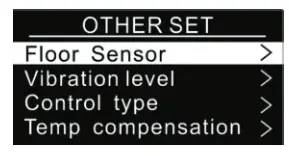 | Select Short press button |
| Temperature Compensation | The displayed temperature may have big tolerance caused by the sensor or other factors, so it is necessary to do temp compensation to the room sensor and floor sensor. The compensation range is -5 ~ +5°C, stepping is 0.5°C. This parameter can also be configured through Advance Config parameters [11] and [12]. | |
| Re-power Status | Press and hold F and buttons for over 10S,then the child lock can be activated or cancelled. When child lock is activated, then icon will appear on the display. | |
| Display Auto Off Function Activation | On the Home Interface, press and hold both F and buttons for over 10S, during the process, the icon will flash slowly, the Display Auto OFF function can be enabled or disabled, when the function is enabled, the icon will be displayed, otherwise the icon will not be displayed. This parameter can also be configured through Advance Config parameter [27] . |
Z-Wave Set Introduction
1. Z-Wave Network Management
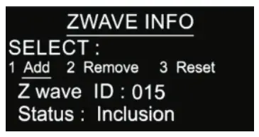
Select![]() ZWAVE INFO on Home Interface to enter into Z-Wave network management interface as follow:
ZWAVE INFO on Home Interface to enter into Z-Wave network management interface as follow:
Adding to a Z -Wave Network ( Inclusion)
Method 1: Select “Add”, then short press button F, the device will send out inclusion request, “Status” will show “Inclusion…”. If there is no response from a gateway within 30 seconds, or inclusion failed, “Status” will show “Fail”. If included successfully, “Status” will show “Inclusion OK” and device ID.
Method 2: Operate the gateway into inclusion mode, make sure the device is already removed from the previous network, reset power of the device, the device will be ncluded in the gateway automatically.
Removing from a Z-Wave Network (Exclusion)
Select “Remove”, then short press button, the device will send out exclusion request, “Status” will show “Exclusion…”. If there is no response from a gateway within 30 seconds, or exclusion failed, “Status” will show “Fail”. If excluded successfully, “Status” will show “Exclusion OK” and device ID will be shown as 0.
Factory Reset (Reset)
Factory resetting will reset all Advance Config parameters to the default value, and the device will be removed from the Z-Wave network.
Select “Reset”, then short press button F , the device will start reset, “Status” will show “Reset…”. If there is no response from a gateway within 6 seconds, or exclusion failed, “Status” will show “Fail”. If reset successfully, “Status” will show “Reset OK”.
Note 1: if the device is excluded or reset successfully, the Auto Mode Schedule will be reset to the default value.
Note 2: the sent frame of inclusion and exclusion is the INFO frame.
2. Basic set command class
Set the device operation mode as Comfort Mode (Manual Mode) by sending command class basic set = 0XFF. Set the device operation mode as OFF mode by sending command class basic set = 0x00
Z-Wave Technical Specifications
1. Supported Notification Report and Sensor Type
| Notification Type | Triggering Event | Description |
| POWER_MANAGEMENT | POWER_MANAGEMENT_OVERCURRENT_DETECTED | Over Current Alarm |
| Heat Alarm | Overheat detected | Over Heat Alarm |
| SENSOR MULTILEVEL Type support | Scale |
| Air temperature | Celsius (℃) |
Technical Specifications
| Item | Definition |
| SDK | 6.82.00 |
| Explorer Frame Support | Yes |
| Device Type | Thermostat(HVAC) |
| Generic Device Class | GENERIC_TYPE_THERMOSTAT |
| Specific Device Class | SPECIFIC_TYPE_THERMOSTAT_HEATING |
| Role Type | Always On Slave (AOS)) |
| Routing | Yes |
Thermostat Related Specifications
| Command | Support |
| ThermostatMode | ThermostatMode_OFF(off) ThermostatMode_HEAT(UI displays Manual) ThermostatMode_DRY ThermostatMode_EnergyHeat(UI displays Auto) ThermostatMode_Away(UI displays Away) |
| ThermostatSetPoint | ThermostatSetPointType_Heating(set manual temperature) ThermostatSetPointType_Energy_Save_Heating(set auto temperature) ThermostatSetPointType_DRY ThermostatSetPointType_Away_Heating(set away temperature) |
Supported Command Class
Root Device
| Suppourt Command class | Support S2/s0 | |
| COMMAND_CLASS_ZWAVEPLUS_INFO | V2 | |
| COMMAND_CLASS_SECURITY | V1 | |
| COMMAND_CLASS_SECURITY_2 | V1 | |
| COMMAND_CLASS_TRANSPORT_SERVICE | V2 | |
| COMMAND_CLASS_SUPERVISION | V1 | |
| COMMAND_CLASS_THERMOSTAT_MODE | V3 | YES |
| COMMAND_CLASS_THERMOSTAT_OPERATING_STATE | V1 | YES |
| COMMAND_CLASS_THERMOSTAT_SETPOINT | V2 | YES |
| COMMAND_CLASS_ASSOCIATION | V2 | YES |
| COMMAND_CLASS_MULTI_CHANNEL_ASSOCIATION | V3 | YES |
| COMMAND_CLASS_ASSOCIATION_GRP_INFO | V1 | YES |
| COMMAND_CLASS_VERSION | V3 | YES |
| COMMAND_CLASS_MANUFACTURER_SPECIFIC | V2 | YES |
| COMMAND_CLASS_DEVICE_RESET_LOCALLY | V1 | YES |
| COMMAND_CLASS_POWERLEVEL | V1 | YES |
| COMMAND_CLASS_TIME_PARAMETERS | V1 | YES |
| COMMAND_CLASS_CONFIGURATION | V1 | YES |
| COMMAND_CLASS_NOTIFICATION | V8 | YES |
| COMMAND_CLASS_METER | V3 | YES |
| COMMAND_CLASS_MULTI_CHANNEL | V4 | YES |
| COMMAND_CLASS_FIRMWARE_UPDATE_MD | V4 | YES |
| Controlled command class | Support S2/s0 | |
| COMMAND_CLASS_THERMOSTAT_MODE | V3 | YES |
| COMMAND_CLASS_THERMOSTAT_SETPOINT | V2 | YES |
Note: the EndPoint01 mirrors equivalent effect root endpoint.
EndPoint1 command list:
| Support command class | Support S2/s0 | |
| COMMAND_CLASS_ZWAVEPLUS_INFO | V2 | |
| COMMAND_CLASS_SECURITY | V1 | |
| COMMAND_CLASS_SECURITY_2 | V1 | |
| COMMAND_CLASS_SUPERVISION | V1 | |
| COMMAND_CLASS_SENSOR_MULTILEVEL | V5 | YES |
| COMMAND_CLASS_ASSOCIATION | V2 | YES |
| COMMAND_CLASS_MULTI_CHANNEL_ASSOCIATION | V3 | YES |
| OMMAND_CLASS_ASSOCIATION_GRP_INFO | V1 | YES |
| COMMAND_CLASS_THERMOSTAT_MODE | V3 | YES |
| COMMAND_CLASS_THERMOSTAT_OPERATING_STATE | V1 | YES |
| COMMAND_CLASS_THERMOSTAT_SETPOINT | V2 | YES |
EndPoint2 (floor temperature sensor) command list:
| Support command class | Support S2/S0 | |
| COMMAND_CLASS_ZWAVEPLUS_INFO | V2 | |
| COMMAND_CLASS_SECURITY | V1 | |
| COMMAND_CLASS_SECURITY_2 | V1 | |
| COMMAND_CLASS_SUPERVISION | V1 | |
| COMMAND_CLASS_SENSOR_MULTILEVEL | V5 | YES |
| COMMAND_CLASS_ASSOCIATION | V2 | YES |
| COMMAND_CLASS_MULTI_CHANNEL_ASSOCIATION | V3 | YES |
| COMMAND_CLASS_ASSOCIATION_GRP_INFO | V1 | YES |
Association
Root device
| Group ID | NAME | Profile | Max nodes | Description |
| 1 | Lifeline | AGI_LIFE_LINE(0x0001) | 5 | 1. Send Command Class DEVICE_RESET_LOCALLY_NOTIFICATION to associated devices of this group when the factory reset the device. 2. Send Command Class THERMOSTAT_SETPOINT_REPORT, THERMOSTAT_MODE_REPORT, THERMOSTAT_OPERATING_STATE_REPORT to associated devices of this group When operation mode and temperature change. 3. Send Command Class NOTIFICATION_REPORT to associated devices of this group when over-current, overheat detected 4. Send Command Class METER_REPORT to associated devices of this group to report metering parameters. |
| 2 | Heat Set | AGI_CONTROL_ KEY01 (0x2001) | 5 | Transfer Command Class THERMOSTAT_SETPOINT_SET THERMOSTAT_MODE_SET to control other temperature control devices when operation changes |
EndPoint01 :
| Group ID | NAME | Profile | Max nodes | Description |
| 1 | Lifeline | AGI_LIFE_LINE (0x0001) | 0 | Lifeline(0x0001) |
Note: the EndPoint01 has an equivalent effect of the root function. EndPoint02
| Group ID | NAME | Profile | Max nodes | Description |
| 1 | Lifeline | AGI_LIFE_LINE(0x0001) | 0 | Lifeline(0x0001) |
Advance Config Parameters
| Parameter | Size | Description | Default Value | Parent Menu |
| 0x02(2) | 1 | Over-current detection max. value, unit is A. When the detected current is over this value, the device will turn off the relay and send NOTIFICATION CC. 0, disable overcurrent detection 5-16, over current detection max. value | 16 | Monitor Set |
| 0x03(03) | 1 | Vibration level and buzzer level triggered by pressing buttons 0, disable vibration and buzzer 1, Low Level 2, High Level | 1 | Other Set |
| 0x04(4) | 1 | Whether to recover to settings before power failure or power reset 0, use default settings 1, recover to settings before power failure, or power reset | 1 | Other Set |
| 0x06(6) | 1 | High-temperature detection max. value, unit is ℃ when either temperature sensor is higher than this value, the device will turn off the relay and send NOTIFICATION CC. 0, disable this function 20-60, the high-temperature value | 27 | Monitor Set |
| 0x07(7) | 1 | Temperature control hysteresis value setting, setting range 0.5℃- 2℃ 5-20, unit is 0.1℃ | 5 | Monitor Set |
| 0x08(8) | 1 | Auto mode (Energy save mode) temperature schedule 0, use schedule set by the user 1, use Energy_Save_Heating temperature set by THERMOSTAT_SETPOINT_SET | 0 | None |
| 0x09(9) | 1 | Select floor temperature sensor type 1, NTC/10KB(25/50°C)=3950 2, NTC/15KB(25/50°C)=3950 3, NTC/50KB(25/50°C)=3950 4, NTC/100KB(25/50°C)=3950 | 1 | Other Set |
| 0x0A(10) | 1 | Temperature control reference selection 1, room sensor2, floor sensor 3, room+floor sensor | 1 | Other Set |
| 0x0B(11) | 1 | ROOM SENSOR temperature compensation setting -10~10, unit is 0.5℃ | 0 | Other Set |
| 0x0C(12) | 1 | FLOOR SENSOR temperature compensation setting -10~10, unit is 0.5℃ | 0 | Other Set |
| 0x0D(13) | 1 | Set how long the drying mode lasts 5~100, the unit is minute | 30 | Dry Mode Schedule |
| 0x0E(14) | 1 | Set the mode a fter the drying mode ends 0x00 = OFF 0x01 = Manual mode (comfort mode) 0x02 = Auto mode (energy save mode) 0x03 = Away mode | 2 | Dry Mode Schedule |
| 0x10(16) | 1 | When to report temperature relative change threshold value actively, the unit is 0.1℃ 0, disabled let report 2- 10, rep or t when the threshold value is 2- 10 | 2 | None |
| 0x11(17) | 1 | Time interval value for a periodic report of temperature, humidity, unit is S 0, disable to report 30~28800, report when time interval value is 30~28800 | 300 (5mins) | None |
| 0x12(18) | 1 | When to report power change absolute threshold, the unit is W 0, disable to report 1~100, report when the absolute threshold is 1~100 | 5 | None |
| 0x13(19) | 1 | When to report current change absolute threshold, the unit is 0.1A 0, disable to report 1~10, report when the absolute threshold is 1~10 | 10 | None |
| 0x14(20) | 1 | When to report voltage change absolute threshold, the unit is 1 V 0, disable to report 1~10, report when the absolute threshold is 1~10 | 2 | None |
| 0x15(21) | 4 | Time interval value for periodic active report of Meter 60-2678400 (31 days), unit is S | 600 (10mins) | None |
| 0x16(22) | 1 | The OLED displays brightness when operating the device. 0, low level 1, mid-level 2, high level | 1 | Other Set |
| 0x17(23) | 1 | This parameter defines which sensor temperature will be displayed on the Home page. 0x00: indoor air temperature 0x01: external temperature (floor temperature) | 0 | Other Set |
| 0x18(24) | 1 | The time zone that the time parameters command adopts is UTC, the time zone needs to be set: +12 ~ -12 | 0 | Other Set |
NAMRON Z-WAVE RELÉ 16A ![]()
Important: Read All Instructions Prior to Installation
Function introduction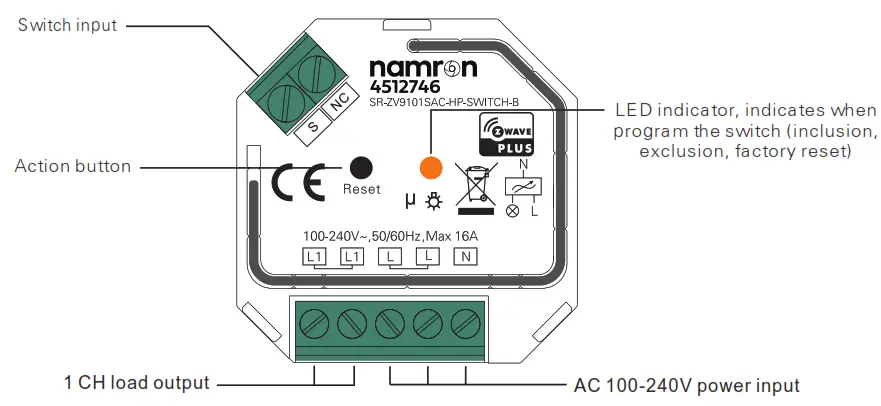
Produc t Data
| Z-Wave Frequency | 868.42 MHZ ( EU) |
| Input Voltage | AC100-240V |
| Output Voltage | AC100-240V |
| Output Current | 16A max. |
| Operating temperature | 0 to 40°C |
| Relative humidity | 8% to 80% |
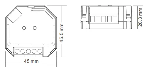
| Dimensions | 45.5x45x20.3mm |
Compatible Load T ypes
| Load Symbol | Load Type | Maximum Load | Remarks |
| LED lamps with transformers | 1220W @ 2 30V 580W @ 1 10V | Due to variety of LED lamp designs, maximum number of LED lamps is further dependent on power factor result when connected to switch. | |
| LED drivers | 1220W @ 2 30V 580W @ 1 10V | Maximum permitted number of drivers is 1220W divided by driver nameplate power r ating. | |
| Incandescent lighting, HV Halogen lamps | 3680W @ 2 30V 1760W @ 1 10V | Max. continuous load 10A | |
 | Low voltage halogen lighting with electronic transformers | 1220W @ 2 30V 580W @ 1 10V | |
 | Electrical appliances such as television, refrigerator, water heating etc. | 3680W @ 2 30V 1760W @ 1 10V | Max. continuous load 10A |
Safety & Warnings
- DO NOT install with power applied to device.
- DO NOT expose the device to moisture.
Quick Start
How to install:
- Step 1: power on the Z-Wave in-wall switch.
- Step 2: activate inclusion mode on your Z-Wave controller.
- Step 3: activate inclusion mode of the switch by triple press the action button on the switch. The switch will be included to Z-Wave network.
Produc t Des c ription
The in-wall switch is a Z -Wave device that is used to switch ON/OFF the connected light or electrical appliances and can be controlled by other Z-Wave devices. The In-wall switch can be included and operated in any Z-Wave network with other Z-Wave certified devices from other manufacturers and/or other applications. All non-battery operated nodes within the network will act as repeaters regardless of vendor to increase reliability of the network
This device supports the SmartStart inclusion. SmartStart enabled products can be added into a Z -Wave network by scanning the Z-Wave QR C ode present on the product with a controller providing SmartStart inclusion. No further action is required and the SmartStart product will be added automatically within a period after the QR code being scanned or reset power of the device. Please find the QR code on the device casing. The encryption mode that the switch supports is S2 Unauthenticated. When the switch is being included into a Z-Wave network, you can use your primary controller/gateway to enable encryption mode or disable encryption. (The primary controller/gateway shall support encryption mode configuration). The switch supports OTA and can update firmware wirelessly. In addition, the switch is equipped with Power Metering and over current protection.
Operation
Installation G uide
Please read carefully the enclosed user manual before installation of the in-wall switch, in order to ensure an error-free functioning.
ATTENTION: Prior to the assembly of the product, the voltage network has to be switched OFF a nd ensured against re-switching.
Inclusion (adding to a Z-Wave network)
- Set primary controller/gateway into inclusion mode (Please refer to your primary controllers manual on how to turn your controller into inclusion).
- Power on the in-wall switch and set it into inclusion mode. There are two methods to set the in-wall switch into inclusion mode:
1)Triple press the action button on the switch, LED indicator will flash rapidly, it will set the switch into inclusion mode for 30 seconds, if there is no reply from the gateway, the device will quit inclusion mode after 30 seconds. 2)When the value of parameter 5 is configured as 1, triple press the external switch rapidly within 1.5 seconds, LED indicator will flash rapidly, it will set the switch into inclusion mode for 30 seconds, if there is no reply from the gateway, the device will quit inclusion mode after 30 seconds. The LED indicator will stay solid on for 3 seconds if the device is added to the network successfully. The indicator will turn off if inclusion fails.
Exclusion (removing from a Z-Wave network)
There are two exclusion methods:
Method 1: Exclusion from the primary controller/gateway as follows:
- Set the primary controller/gateway into exclusion mode (Please refer to your primary controllers manual on how to set your controller into exclusion).
- Power on the in-wall switch and set it into exclusion mode. There are two methods to set the in-wall switch into exclusion mode:
1)Triple press the action button on the switch, LED indicator will flash rapidly, it will set the switch into exclusion mode for 30 seconds, if there is no reply from the gateway, the device will quit exclusion mode after 30 seconds.
2)When the value of parameter 5 is configured as 1, triple press the external switch rapidly within 1.5 seconds, LED indicator will flash rapidly, it will set the switch into exclusion mode for 30 seconds, if there is no reply from the gateway, the device will quit exclusion mode after 30 seconds.
The LED indicator will stay solid on for 3 seconds if the device is removed from the network successfully. The indicator will turn off if exclusion fails.
Method 2: Factory reset the switch will force the switch to be excluded from a network. (please refer to the part “Factory Reset” of this manual)
Note: Factory reset is not recommended for exclusion, please use this procedure only if the primary controller/gateway is missing or otherwise inoperable.
Factory Reset
Press and hold down the action button for over 10 seconds, LED indicator flashes slowly, the switch will restart and reset to factory defaults.
Scene Control
Users can configure scenes using command class SCENE_ACTUATOR_CONF_SET, and activate the scenes using command class SCENE_ACTIVATION_SET.
Association
Z-Wave devices control other Z-Wave devices. The relationship between one device controlling another device is called association. In order to control a different device, the controlling device needs to maintain a list of devices that will receive controlling commands. These lists are called association groups and they are always related to certain events (e.g. button pressed). In case the event happens all devices stored in the respective association group will receive a common wireless command.
Association Groups :
| Association Groups | Group Name | Max Nodes | Description |
| Group 1 | Lifeline | 5 | 1. When press and hold down “Reset” button for 10S to reset the device, send ” Device Reset Locally Notification” to associated devices of this group to report factory reset information. 2. When over load detected, send ” OTIFICATION_REPORT”to associated devices of this group. 3. Report energy meter actively. 4. Send basic report automatically. |
Set and uns etass ociations :
(Note: All association information will be cleared automatically once the switch is excluded from a network.)
Set association by operating primary controller/gateway to send packets to the switch:
The primary controller/gateway sends packets to the switch using “Command Class ASSOCIATION”
Node Information Frame
The Node Information Frame is the business card of a Z-Wave device. It contains information about the device type and the technical capabilities. The inclusion and exclusion of the device is confirmed by sending out a Node Information Frame. Beside this it may be needed for certain network operations to send out a Node Information Frame. How to send out Node Information Frame:
When the switch is set to inclusion/exclusion mode again, it will send out Node Information Frame, there are 2 kinds of operation as follows:
- Triple press the action button, the dimmer will be set to inclusion/exclusion mode, then send out Node Information Frame.
- When the switch is under inclusion mode, there are two kinds of operation:
1) Triple press inclusion/exclusion button, the switch will be set to inclusion mode again, and send out Node Information Frame.
2) P ower off and power on the switch, it will be set to inclusion mode automatically, and send out Node Information Frame.
Technical Data
| Wireless Range | up to 100 m outside, on average up to 40 m inside buildings |
| SDK | 7.13.6.0 |
| Explorer Frame Support | Yes |
| Device Type | On/Off Power Switch |
| Generic Device Class | GENERIC_TYPE_SWITCH_BINARY |
| Specific Device Class | SPECIFIC_TYPE_POWER_SWITCH_BINARY |
| Role Type | Always On Slave (AOS) |
| Routing | Yes |
Supported Command Class
| Node Info | Security Command Supported Report | ||
| COMMAND_C LASS_ZWAVE PLUS_I N F 0 | V2 | COMMAND_CLASS_MANUFACTURER_SPECIFIC | V2 |
| COMMAND_CLASS_TRANSPORT_SERVICE | V2 | COMMAND_C LASS_VE R SION | V3 |
| COMMAND_C LASS_SE CUR ITY | V1 | COMMAND_CLASS_SWITCH_BINARY | V2 |
| C OMMAND_C LASS_SEC UR ITY_2 | V1 | COMMAND_CLASS_SCENE_ACTIVATION | V1 |
| COMMAND_CLASS_SUPERVISION | V1 | OMMAND_CLASS_SCENE_ACTUATOR_CONF | V1 |
| COMMAND_CLASS_METER | V5 | ||
| COMMAND_C LASS_NOTIF !CATION | V8 | ||
| C OMMAN D_C LASS_CONF IG UR ATION | V1 | ||
| COMMAND_CLASS_ASSOCIATION_GRP_INFO | V1 | ||
| COMMAND_CLASS_ASSOCIATION | V2 | ||
| COMMAND_CLASS_FIRMWARE_UPDATE_MD | V4 | ||
| COMMAND_CLASS_POWERLEVEL | V1 | ||
| COMMAND_CLASS_DEVICE_RESET_LOCALLY | V1 | ||
| COMMAND_CLASS_INDICATOR | V3 | ||
Notific ation R eport
| Notification Type | Triggerring Event |
| NOTIFICATION_TYPE_POWER_MANA GEMENT(08) | POWER_MANAGEME NT_OVERCUR RENT_ DETECTED(06) |
| NOTIFICATION_TYPE_POWER_MANA GEMENT(08) | POWER_MANAGEMENT_OVERLOADED_N T DETECTED(08) |
Over Current Alarm: When connecting to resistive load, over current protection value is 16A.
Note: When over current or overload protection is enabled (value of configuration parameter 4 not configured as 0), if the device detects that the load current is over 16A or power is over 3700W, the relay will be forced to off, unless reset power of the device, otherwise the device will always be at alarm status, and report alarm every 60 seconds.
Configuration Command Class
| Para meter | Size | Description | Default Value |
| 0x02(2) | 1 | nfo: Saving load state before power failure 0- shutoff load 1- turn on load 2 save load state before power failure | 2 |
| 0x03(3) | 1 | nfo: Enable/disable to send the basic report to the Wenn., :ran the load statechanged 0- Disable to send Basic report 1 – Enable to send Basic report | 1 |
| 0x04(4) | 1 | E ‘able/disable over current or over load protection. repo-. larm when the load is over 164. if enabled 0. disable 1’ enable | 1 |
| 0x05(5) | 1 | External switch type pushbutton switch ‘ normal on/off switch | 0 |
| 0x07(7) | 1 | ,, dated to and removed from a network through external mtch (when enables this function, triple press the am—. ..mtch to be added to or removed from anetwork) – disable ‘ – enable’late: if this function is enabled. when triple press the wtch rapidly. the device will beset to inclusion or -.elusion mode, then device status will not be reported nasic report) during this process. | 1 |
| 0x0A(10) | 1 | = mot change absolute threshold report. report Menthe Dover change value is over the threshold. unit is W : disable absolute threshold report function ‘ -255: value of the power change absolute threshold. if r. ower change value is over the threshold value. reoc,t owor change value using METER_REPORT | 5 |
| 0x0B(11) | 1 | I. -.irrent change absolute threshold. unit is 0.1A : disable absolute threshold function ‘ -255:value of the current change absolute threshold. if :-trent change value is over the threshold va lue. report the _Jrrent change value using ETER_REPORT | 1 |
| 0x0C(12) | 1 | . Dltage change absolute threshold. unit is 1V : disable absolute threshold function ‘ -255:value of the voltage change absolute threshold. tf .oltage change value is over the threshold value. report -.. • . Dltage change value using METER_REPORT | 2 |
| 0x0d(13) | 4 | -me cycle to report the values of energy cnsumpuon, voltage, current and load power -ctively 3′ days). value of theme cycle. un 1 | 1800(30mins) |
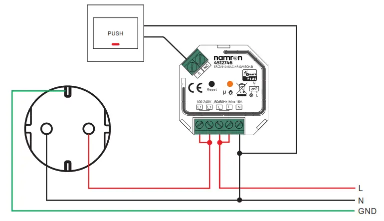
Wiring Diagram
Notes f or the d iagrams :
L – termina l for live lea d
N – termina l for neutra l lea d
L1 – output termina ls of the device (controlling connected light source)
S – termina l for externa l switch
NC – No Connection
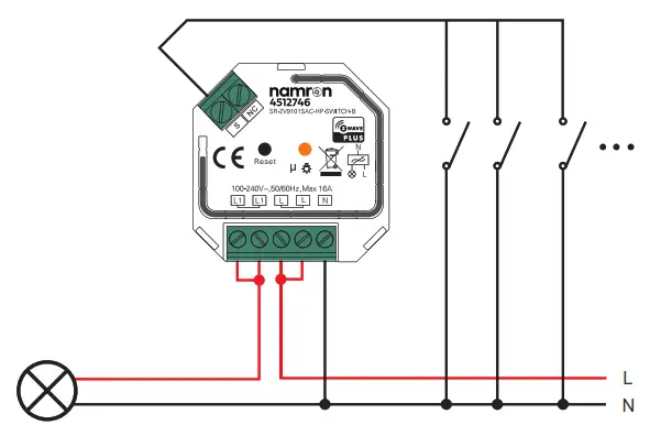
- With Normal On/Off Switch

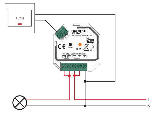
- With Single Push Button Switch

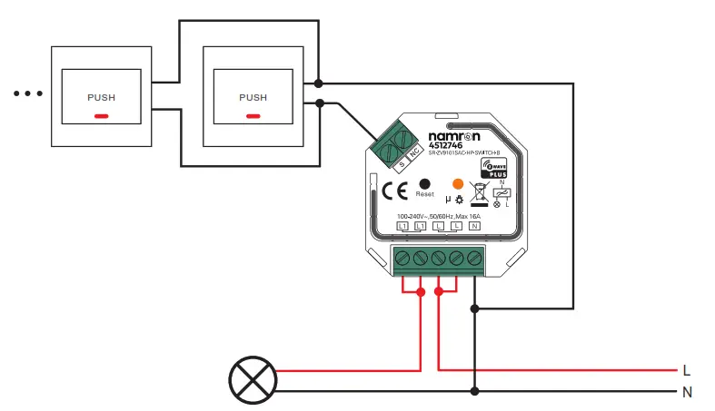
- With Multiple Push Switches for Multiple Control Points

- Connect With Socket

Product Dimension
![]() Namron AS
Namron AS
Nedre kalbakkvei 88B
1081 Oslo
Norway
[email protected]


