Z-Wave SR-ZV9092A Heating Thermostat
Function introduction

Product Data
| Z-Wave Frequency | 868.42MHz (EU) |
| Input Voltage | EU: AC200-240V, 50/60Hz |
| Output Voltage | EU: AC200-240V |
| Max Load | 3680W @ 230V (resistive load) |
| Max Current | 16A |
| Power Consumption | <2W |
| Ambient Temperature | 0°C to 40°C (during operation) |
| Set Temperature Range | 0°C to 40°C |
| Hysteresis | 0.5°C to 2°C (default 0.5°C) |
|
Floor sensor type | 1. NTC/10K B(25/50℃)=3950 (default) 2. NTC/15K B(25/50℃)=3950 3. NTC/50K B(25/50℃)=3950 4. NTC/100K B(25/50℃)=3950 |
| Control Mode | OFF, HEAT, ENERGY HEAT, AWAY, DRY |
|
Control Type | Control type means which temperature sensor the device refers to when it adjust temperature. Room sensor: adjust temperature refers to room temperature (factory default type). Floor sensor: adjust temperature refers to floor temperature. Room+Floor sensor: adjust temperature refers to both room temperature and floor temperature. |
| Wiring Requirement | Current ≤ 13A – 1.5mm² solid core wire Current > 13A to 16A – 2.5mm² solid core wire |
| IP Rating | IP21 |
| Control Pollution Degree (Method D) | pollution degree 2 |
| Rated Impulse Voltage (Method D) | 4kV |
| Relative Humidity | 8% to 80% |
| Dimensions | 80x80x52mm |
| Approvals | Z-Wave Plus, CE, LVD: EN 60730-1:2016;A1, EN IEC 60730-2-9:2019;A1 EMC & RF: EN IEC 61000-3-2:2019, EN 61000-3-3:2013+A1:2019, EN 60730-1:2016+A1:2019, EN 60730-2- 19:2019+A1:2019+A2:2020, EN 50663:2017;ETSI EN 301 489- 1V2.2.3, ETSI EN301 489-3V2.1.1 ETSI EN300 220-1 v3.1.1., ETSI EN300 220-2 V3.2.1 RED certificate: 2014/53/EU |
- The Z-Wave HVAC controller is a wireless thermostat for heating system, which complies to Z-Wave Plus wireless protocol standards. The thermostat has 4 operation modes which can be controlled manually and locally or through remote controlled through Z-Wave primary controller (gateway).
- The thermostat can be included and operated in any Z-Wave network with other Z-Wave certified devices from other manufacturers and/or other applications. All non-battery operated nodes within the network will act as repeaters regardless of vendor to increase reliability of the network.
- The encryption mode that the thermostat supports are S0, S2 Unauthenticated. When the thermostat is being included into a Z-Wave network, you can use your primary controller/gateway to enable encryption mode or disable encryption. (The primary controller/gateway shall support encryption mode configuration). The thermostat supports OTA and can update firmware wirelessly.
- Sensors: Air temperature
- THERMOSTAT MODE: OFF, HEAT, ENERGY HEAT, AWAY, DRY
- Measurement range: –10°C to +60°C
- Accuracy: ±0.1°C
- WARNING: Electrical power must be switched off during installation
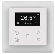
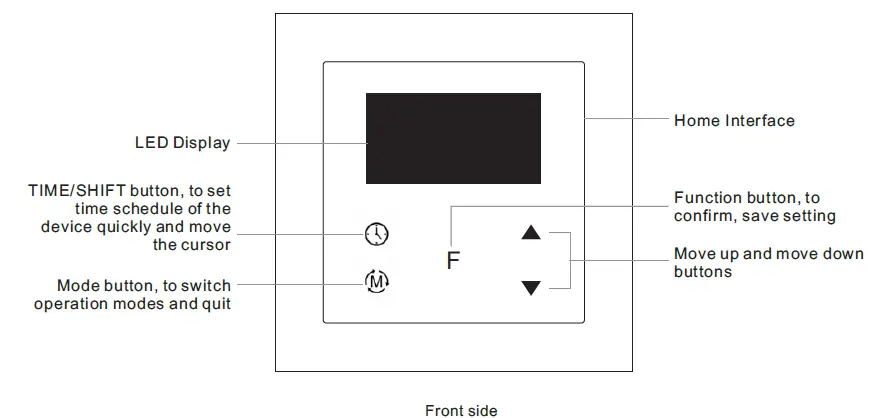
Home Interface
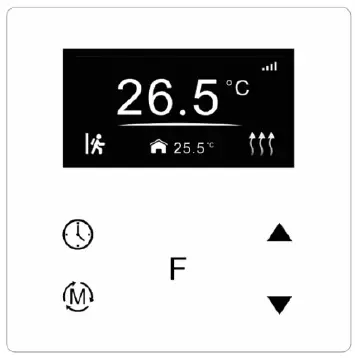
Already included to a Z-Wave network:
Child Lock enabled: Lock
Week display: MON, TUE, WED, THU, FRI, SAT, SUN The set temperature: Set 28.5℃
Room temperature: 25.5℃
Floor temperature: temperature
Standby Interface
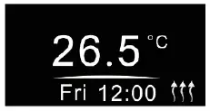
If there is no operation within 2 minutes, the device will go to this standby interface.
Safety & Warnings
- DO NOT install with power applied to device.
- DO NOT expose the device to moisture.
Basic Function Introduction
- Switch Operation modes
Short press button on Home interface to switch operation modes: the icons of Away, Manual (Comfort), Automatic (Energy Save), Drying, OFF modes will be displayed alternatively for 3 seconds and last displayed mode will be selected, or just short press button to select a desired mode when the modes’ icon displayed alternatively. Press and hold button on Home interface for over 3 seconds to select Away mode directly, then press and hold button for 3 seconds to quit Away mode.
OFF Mode: this mode means that the device is under idle status.
Manual (Comfort Mode): the device will control the heating system according to current set temperature. The temperature can be set by move up and move down button on the Home interface, or configured by Z-Wave gateway.
Automatic (Energy Save Mode): the device will control the heating system according to the configured time schedule or Z-Wave protocol Energy_Save_Heating Setpoint.
Away (Away Mode): the device will control the heating system according to the set temperature within the set period.
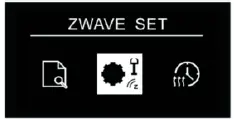
Drying (Drying Mode): The device will judge the set temperature for heating within a short period of time. - Z-Wave Set Interface
Under Home interface, meanwhile the device is at OFF mode , press and hold move up and move down buttons at the same time for over 5 seconds to enter into Z-Wave Set Interface as follows: Quit: on Z-Wave Set Interface short press button to go back to Home interface.
Enter into set interface of each setting item: short press move up or move down button to select a setting item, then short press button F to enter into set interface of the selected item. - Preview of Device Information
On Home Interface, user can enter into PREVIEW interface, the interface will display some basic configurations, energy consumption, date, floor temperature etc. - Auto Mode Schedule
Note:- When configuration parameter 8 value set as 1, the device will control the temperature of energy save mode according to the temperature set by Command Class Energy_Save_Heating Setpoint or set by using the move up and move down buttons, following mentioned schedule will be invalid.
- When configuration parameter 8 value set as 0, the temperature set by Command Class Energy_Save_Heating Setpoint and set by using the move up and move down buttons will both be invalid, Energy Save Mode will control temperature according to following user schedule.
For instance, if user would like to keep room temperature at 18 degree Celsius during 18:00-23:00 on every Monday, and keep room temperature at 20 degree Celsius after 22:30 on every Monday, then user can set schedule by himself.
 Quit: on Z-Wave Set Interface short press button to go back to Home interface.
Schedule setting method 1: user can enters into schedule on Z-Wave Set Interface, the schedule 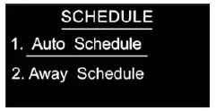
Short press button to select “Auto Schedule”, then short press button F to enter into Auto Mode Schedule weekly setting interface.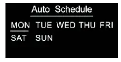
Schedule setting method 2: on Home Interface, meanwhile the device is under Auto Mode , short press button to enter into Auto Mode Schedule weekly setting interface quickly:
On Auto Mode Schedule weekly setting interface, use buttons and F to enter into schedule setting of a certain week as follows: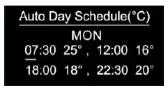 On Auto Day Schedule interface, short press button to select the time or temperature that you would like to modify, then short press move up and move down buttons to modify value, then short press button F to save and quit, short pressing button only quits without saving.
For each schedule, the latter time should be later than the former time, otherwise saving will fail with the error remind “Time setting error!!!”. The default time schedules are as follows:
Monday ~ Friday
7:30,24℃ ~ 12:00,20℃
18:00,16℃ ~ 22:30,18℃
Saturday~Sunday
7:30,24℃ ~ 12:00,20℃
18:00,18℃ ~ 22:30,18℃
Away Mode Schedule
User can set time to leave home and time to go home according to the requirements of themselves, and set how the device will control the temperature during this period.
- If away mode has already been activated, the end time for away mode is valid, the device will execute Away Mode Temperature Schedule before the end time.
- If away mode has already been activated, the values of end time for away mode are set as 0, the device will always execute current set temperature with no time limitation. The device will consider the mode as anti-freeze mode, the recommended temperature setting is 4-10℃.
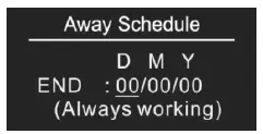
D means date, M means month, Y means year (2019-2099).
Start and end mean away time.
To enter into the setting interface and setting method, please refer to the 1.4 Auto Mode (Energy Save Mode) Schedule.
Dry Mode Schedule
For example, in order to quickly dry the water in the bathroom, the device can be set to quickly heat in a short time to dry the floor. Enter the configuration interface as follows:
Duration: set how long the dry mode lasts
After Mode: set the mode after the drying mode ends
Remain: shows the remaining time of the drying mode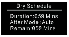
For configuration method and modification, please refer to Automatic Mode (Energy Save Mode) Schedule:
MONITOR SET
The function of monitor set is real time monitor of over current, over heat and freezing, on Home interface, short press MONITOR SET to enter into monitor set interface as follows:
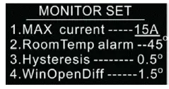
Max Current (16A by default)
If current is over the set value, the relay will be forced to off by the device, and the state will be reported to the gateway. The over current alarm function can be disabled, which can be set directly through the device. Or can be configured through Advance Config parameter 2 by setting the value as 0 to disable the function, please refer to the part “Advance Config”.
RoomTemp Alarm (45°C by default)
If room temperature is over the set value, the relay will be forced to off by the device, and over heat alarm will be reported to the associated devices, meanwhile the buzzer or vibrator will beep 3 times every 10 seconds. The over heat alarm function can be disabled, which can be set directly through the device. Or can be configured through Advance Config parameter 6 by setting the value as 0 to disable the function, please refer to the part
“Advance Config”.
Over heat alarm interface is as follow: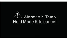
Note: to cancel over current alarm or over heat alarm, just press and hold button for over 3 seconds or reset power of the device. After cancel manually, the relay will show heating forbidden icon within 120 seconds, but other operations are allowed.
Hysterersis (0.5°C by default)
To prevent the undulation of sensor temperature when the sensor temperature is approaching the set temperature, which will cause that the controller may keep switching on/off the relay. Here hysterersis enables the controller to control the relay only when the sensor temperature is a little bit lower than the set temperature, this value can be set. This hysterersis only valid when the control type is single sensor, please refer to the part Control Type.
For instance, when hysterersis is set as 0.5 degree, then only when current sensor temperature is 0.5 degree lower than the set temperature, will the controller heat, if the sensor temperature >= set temperature, the controller will not heat.
Window Open Detect (disabled by default)
Once the device is powered on and stable, referring to the room temperature sensor, if the temperature decreases to the threshold of this setting, the window open mark will be enabled, the relay will be forced to turn off to save energy, then the icon will appear.
After window open mark is enabled, if the temperature increases to the threshold of this setting in 3 minutes, the window open mark will be disabled.
Once the window open mark is enabled, it will be disabled after 10 minutes, and the working mode will change to (OFF mode).
The threshold value of this parameter can also be configured through Advance Config parameter [26]. 0 means this function is disabled.
Note: this function will work better when the device is installed beside the window or door.
TIME/DATE SET
Select TIME/DATE on Home Interface to enter into TIME/DATE SET interface as follow:
The time zone that the time parameter command adopts is UTC standard time, the corresponding value range for the time zone range from UTC+12 ~ UTC-12 shall be current UTC standard time+12 ~ UTC standard time-12. This parameter can also be configured through Advance Config parameter [24].
OTHER SET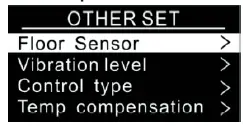
Short press button to select the item would like to modify, then short press move up and move down buttons to modify value of selected item, then short press button F to save and quit, short pressing button only quits without saving.
Floor Sensor (NTC 10K by default)
If external sensor is broken, the user can buy NTC sensor by themselves, the available sensor types are as follows:
NTC 100K/25 (3m,NTC,R25=100KΩ±1%@25℃, B25/50=3950K±1%)
NTC 50K/25 (3m,NTC,R25=50KΩ±1%@25℃, B25/50=3950K±1%)
NTC 15K/25 (3m,NTC,R25=15KΩ±1%@25℃, B25/50=3950K±1%)
NTC 10K/25 (3m,NTC,R25=10KΩ±1%@25℃, B25/50=3950K±1%)
Key vibration level (Low by default)
Set the level of vibration sensor under the buttons or buzzer level.
OFF: vibration or buzzer off
Low Level, High Level: low vibration or buzzer level, high vibration or buzzer level
The level can also be configured through Advance Config parameter 03.
Control type (Room sensor by default)
Control type means which temperature sensor the device refers to when it adjust temperature.
Room sensor: adjust temperature refers to room temperature (factory default type)
Floor sensor: adjust temperature refers to floor temperature
Room+Floor sensor: adjust temperature refers to both room temperature and floor temperature. Turn on heat valve under other circumstances. This mode is to prevent the device from continuous heating that caused by malfunction of either sensor. When the floor sensor temperature is >= the set temperature minus 1 or when the room sensor is >= the set temperature, either of the conditions is achieved, the controller will stop heat, otherwise the controller will heat.
This parameter can also be configured through Advance Config parameter [10].
Temp compensation (0 by default)
The displayed temperature may has big tolerance caused by the sensor or other factors, so it is necessary to do temp compensation to room sensor and floor sensor.
Compensation range is -5 ~ +5℃, stepping is 0.5℃.
This parameter can also be configured through Advance Config parameter [11] and [12] .
RePower status(last status by default)
Device state after reset power of the device.
If set as “last status”, device will go to the status before power failure after power on again.
If set as “default”, device will go to default mode after power on again.
This parameter can also be configured through Advance Config parameter [4].
Display Temp type (Home Temp by default)
This parameter defines which sensor temperature will be displayed on Home page. Floor Temp: floor temperature (external sensor).
Home Temp: indoor air temperature.
This parameter can also be configured through Advance Config parameter [23].
Operate Brightness (Mid Level by default)
The OLED display brightness when operate the device.
High Level, Mid Level, Low Level.
This parameter can also be configured through Advance Config parameter [22].
Z-Wave Set Introduction
Z-Wave Network Management
Select ZWAVE INFO on Home Interface to enter into Z-Wave network management interface as follow: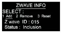
Adding to a Z-Wave Network (Inclusion)
Method 1: Select “Add”, then short press button F , the device will send out inclusion request, “Status” will show “Inclusion…”. If there is no response from a gateway within 30 seconds, or inclusion failed, “Status” will show “Fail”. If included successfully, “Status” will show “Inclusion OK” and device ID.
Method 2: Operate the gateway into inclusion mode, make sure the device is already removed from previous network, reset power of the device, the device will be included to the gateway automatically.
SMART START
If the user’s gateway also supports smartstart, add the device by scanning the QR code,Smartstart allows users to quickly add devices to the gateway by scanning the device’s QR code.
After scanning to add the device, reset power of the device or waiting for a while, the device will be added to the gateway automatically. Please find the QR code on the casing of the device.
Removing from a Z-Wave Network (Exclusion)
Select “Remove”, then short press button F , the device will send out exclusion request, “Status” will show “Exclusion…”. If there is no response from a gateway within 30 seconds, or exclusion failed, “Status” will show “Fail”. If excluded successfully, “Status” will show “Exclusion OK” and device ID will be showed as 0.
Factory Reset (Reset)
Factory resetting will reset all Advance Config parameters to default value, and the device will be removed from the Z-Wave network.
Select “Reset”, then short press button , the device will start reset, “Status” will show “Reset…”. If there is no response from a gateway within 6 seconds, or exclusion failed, “Status” will show “Fail”. If reset successfully, “Status” will show “Reset OK”.
Note 1: if the device is excluded or reset successfully, the Auto Mode Schedule will be reset to default value. Note 2: the sent frame of inclusion and exclusion is INFO frame.
Basic set command class
Set the device operation mode as Comfort Mode (Manual Mode) by sending command class basic set = 0XFF. Set the device operation mode as OFF mode by sending command class basic set = 0x00.
Z-Wave Technical Specifications
Supported Notification Report and Sensor Type
| Notification Type | Triggering Event | Description |
| POWER_MANAGEMENT | POWER_MANAGEMENT_OVERCURRENT_DETECTED | Over Current Alarm |
| Heat Alarm | Overheat detected | Over Heat Alarm |
| SENSOR MULTILEVEL Type support | Scale |
| Air temperature | Celsius (℃) |
Technical Specifications
| Item | Definition |
| SDK | 6.82.00 |
| Explorer Frame Support | Yes |
| Device Type | Thermostat(HVAC) |
| Generic Device Class | GENERIC_TYPE_THERMOSTAT |
| Specific Device Class | SPECIFIC_TYPE_THERMOSTAT_HEATING |
| Role Type | Always On Slave (AOS)) |
| Routing | Yes |
Thermostat Related Specifications
| Command | Support |
| ThermostatMode | ThermostatMode_OFF(off) ThermostatMode_HEAT(UI displays Manual) ThermostatMode_DRY ThermostatMode_EnergyHeat(UI displays Auto) ThermostatMode_Away(UI displays Away) |
| ThermostatSetPoint | ThermostatSetPointType_Heating(set manual temperature) ThermostatSetPointType_Energy_Save_Heating(set auto temperature) ThermostatSetPointType_DRY ThermostatSetPointType_Away_Heating(set away temperature) |
Supported Command Class Root Device
| Suppourt Command class | Support S2/s0 | |
| COMMAND_CLASS_ZWAVEPLUS_INFO | V2 | |
| COMMAND_CLASS_SECURITY | V1 | |
| COMMAND_CLASS_SECURITY_2 | V1 | |
| COMMAND_CLASS_TRANSPORT_SERVICE | V2 | |
| COMMAND_CLASS_SUPERVISION | V1 | |
| COMMAND_CLASS_THERMOSTAT_MODE | V3 | YES |
| COMMAND_CLASS_THERMOSTAT_OPERATING_STATE | V1 | YES |
| COMMAND_CLASS_THERMOSTAT_SETPOINT | V2 | YES |
| COMMAND_CLASS_ASSOCIATION | V2 | YES |
| COMMAND_CLASS_MULTI_CHANNEL_ASSOCIATION | V3 | YES |
| COMMAND_CLASS_ASSOCIATION_GRP_INFO | V1 | YES |
| COMMAND_CLASS_VERSION | V3 | YES |
| COMMAND_CLASS_MANUFACTURER_SPECIFIC | V2 | YES |
| COMMAND_CLASS_DEVICE_RESET_LOCALLY | V1 | YES |
| COMMAND_CLASS_POWERLEVEL | V1 | YES |
| COMMAND_CLASS_TIME_PARAMETERS | V1 | YES |
| COMMAND_CLASS_CONFIGURATION | V1 | YES |
| COMMAND_CLASS_NOTIFICATION | V8 | YES |
| COMMAND_CLASS_METER | V3 | YES |
| COMMAND_CLASS_MULTI_CHANNEL | V4 | YES |
| COMMAND_CLASS_FIRMWARE_UPDATE_MD | V4 | YES |
| Controlled command class | ||
| COMMAND_CLASS_THERMOSTAT_MODE | V3 | YES |
| COMMAND_CLASS_THERMOSTAT_SETPOINT | V2 | YES |
Note: the EndPoint01 mirrors equivalent effect root endpoint.
EndPoint1 command list:
| Support command class | Support S2/s0 | |
| COMMAND_CLASS_ZWAVEPLUS_INFO | V2 | |
| COMMAND_CLASS_SECURITY | V1 | |
| COMMAND_CLASS_SECURITY_2 | V1 | |
| COMMAND_CLASS_SUPERVISION | V1 | |
| COMMAND_CLASS_SENSOR_MULTILEVEL | V5 | YES |
| COMMAND_CLASS_ASSOCIATION | V2 | YES |
| COMMAND_CLASS_MULTI_CHANNEL_ASSOCIATION | V3 | YES |
| COMMAND_CLASS_ASSOCIATION_GRP_INFO | V1 | YES |
| COMMAND_CLASS_THERMOSTAT_MODE | V3 | YES |
| COMMAND_CLASS_THERMOSTAT_OPERATING_STATE | V1 | YES |
| COMMAND_CLASS_THERMOSTAT_SETPOINT | V2 | YES |
EndPoint2 (floor temperature sensor) command list:
| Support command class | Support S2/s0 | |
| COMMAND_CLASS_ZWAVEPLUS_INFO | V2 | |
| COMMAND_CLASS_SECURITY | V1 | |
| COMMAND_CLASS_SECURITY_2 | V1 | |
| COMMAND_CLASS_SUPERVISION | V1 | |
| COMMAND_CLASS_SENSOR_MULTILEVEL | V5 | YES |
| COMMAND_CLASS_ASSOCIATION | V2 | YES |
| COMMAND_CLASS_MULTI_CHANNEL_ASSOCIATION | V3 | YES |
| COMMAND_CLASS_ASSOCIATION_GRP_INFO | V1 | YES |
Association
Root device
| Group ID | NAME | Profile | Max nodes | description |
| 1 | Lifeline | AGI_LIFE_LINE (0x0001) |
5 | 1.Send Command Class DEVICE_RESET_LOCALLY_NOTIFICATION to associated devices of this group when factory reset the device. 2.Send Command Class THERMOSTAT_SETPOINT_REPORT, THERMOSTAT_MODE_REPORT, THERMOSTAT_OPERATING_STATE_REPORT to associated devices of this group When operation mode and temperature change. 3.Send Command Class NOTIFICATION_REPORT to associated devices of this group when over current, over heat detected 4.Send Command Class METER_REPORT to associated devices of this group to report metering parameters. |
| 2 | Heat Set | AGI_CONTROL_KEY01 (0x2001) |
5 | Transfer Command Class THERMOSTAT_SETPOINT_SET THERMOSTAT_MODE_SET to control other temperature control devices when operation changes |
End point 1:
| GroupID | NAME | Profile | Max nodes | description |
| 1 | Lifeline | AGI_LIFE_LINE (0x0001) | 0 | Lifeline |
Note: the EndPoint01 has equivalent effect of root function.
EndPoint 02:
| GroupID | NAME | Profile | Max nodes | description |
| 1 | Lifeline | AGI_LIFE_LINE (0x0001) | 0 | Lifeline |
Advance Config Parameters
| Parameter | Size | Description | Default Value | Parent Menu |
|
0x02(2) |
1 | Over current detection max. value, unit is A. When detected current is over this value, the device will turn off the relay and send NOTIFICATION CC. 0, disable over current detection 5-16, over current detection max. value |
16 |
Monitor Set |
|
0x03(03) |
1 | Vibration level and buzzer level triggered by pressing buttons 0, disable vibration and buzzer 1, Low Level 2, High Level |
1 |
Other Set |
| 0x04(4) | 1 | Whether to recover to settings before power failure or power reset 0, use default settings 1, recover to settings before power failure or power reset | 1 | Other Set |
|
0x06(6) |
1 | High temperature detection max. value, unit is ℃ , when either temperature sensor is higher than this value, the device will turn off the relay and send NOTIFICATION CC. 0, disable this function 20-60, the high temperature value |
45 |
Monitor Set |
| 0x07(7) | 1 | Temperature control hysteresis value setting, setting range 0.5℃-2℃ 5-20, unit is 0.1℃ | 5 | Monitor Set |
| 0x08(8) | 1 | Auto mode (Energy save mode) temperature schedule 0, use schedule set by user 1, use Energy_Save_Heating temperature set by THERMOSTAT_SETPOINT_SET | 0 | None |
|
0x09(9) |
1 | Select floor temperature sensor type 1, NTC/10K B(25/50℃)=3950 2, NTC/15K B(25/50℃)=3950 3, NTC/50K B(25/50℃)=3950 4, NTC/100K B(25/50℃)=3950 |
1 |
Other Set |
|
0x0A(10) |
1 | Temperature control reference selection 1, room sensor 2, floor sensor 3, room+floor sensor |
1 |
Other Set |
| 0x0B(11) | 1 | ROOM SENSOR temperature compensation setting -10~10, unit is 0.5℃ | 0 | Other Set |
| 0x0C(12) | 1 | FLOOR SENSOR temperature compensation setting -10~10, unit is 0.5℃ | 0 | Other Set |
| 0x0D(13) | 1 | Set how long the drying mode lasts 5~100, unit is minute | 30 | Dry Mode Schedule |
|
0x0E(14) |
1 | Set the mode after the drying mode ends 0x00 = OFF 0x01 = Manual mode (comfort mode) 0x02 = Auto mode (energy save mode) 0x03 = Away mode |
2 |
Dry Mode Schedule |
| 0x10(16) |
1 | When to report temperature relative change threshold value actively, unit is 0.1℃ 0, disable to report 2-10, report when the threshold value is 2-10 |
2 |
None |
| 0x11(17) |
1 | Time interval value for periodic report of temperature, humidity, unit is S 0, disable to report 30~28800, report when time interval value is 30~28800 | 300 (5mins) | None |
| 0x12(18) |
1 | When to report power change absolute threshold, unit is W 0, disable to report 1~100, report when absolute threshold is 1~100 | 5 | None |
| 0x13(19) |
1 | When to report current change absolute threshold, unit is 0.1A 0, disable to report 1~10, report when absolute threshold is 1~10 | 10 | None |
| 0x14(20) |
1 | When to report voltage change absolute threshold, unit is 1 V 0, disable to report 1~10, report when absolute threshold is 1~10 | 2 | None |
| 0x15(21) | 4 | Time interval value for periodic active report of Meter 60-2678400 (31 days), unit is S | 600 (10mins) | None |
| 0x16(22) |
1 | The OLED display brightness when operate the device. 0, low level 1, mid level 2, high level | 1 | Other Set |
|
0x17(23) |
1 | This parameter defines which sensor temperature will be displayed on Home page. 0x00: indoor air temperature 0x01: external temperature (floor temperature) |
0 |
Other Set |
| 0x18(24) | 1 | The time zone that the time parameters command adopts is UTC, the time zone need to be set: +12 ~ -12 | 0 | Other Set |
| 0x1A(26) | 1 | Window open detect function temperature threshold: the Celsius degrees that the temperature decreases within 3 minutes, unit is 0.5 Celsius degree. 0, disbaled 3-8, the set temperature threshold | 0 | Monitor Set |
Troubleshooting:
- External (floor) sensor temperature tolerance is too big Possible reason: the selected sensor type is not correct
- The gateway can not set temperature when energy save mode is selected
The temperature schedule (parameter 8) of auto mode (energy save mode) is not configured correctly - Current temperature is not executed when away mode is selected
Check whether away mode time is set as 0 or within valid time range - Over heat alarm when power on the device Possible reason: the set sensor type is not correct or sensor type after factory reset is not correct
- Device time is not the same as the gateway controller after included to the network
Set the device time and time zone manually after included to the gateway network - The tolerance of the indoor temperature sensor is high after powered on Possible reason: due to temperature effect, we need to wait for a while
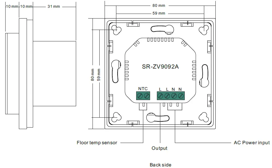
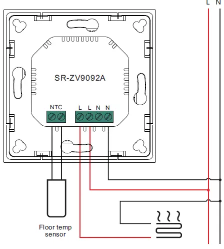
Wiring diagram
This device should be installed by a licensed electrician in a manner that conforms to local regulations and building codes. Provide these instructions to the licensed electrician who is installing the device.
WARNING: Electrical power must be switched off during installation.
- Placement of the device is of utmost importance for proper operation and must be away from sunlight and sources of direct heat. We recommend installing the device approximately 1.5 meters above the floor.
- Remove the display unit and backplate of the device from the packaging.
- FIRST ENSURE THE POWER IS OFF at the main circuit breaker, and then test the wires with a probe or multimeter to verify. Insert the power and heater wires to the correct device terminals by inserting a small Phillips-head screwdriver in the slot beneath each terminal to open. Follow the connection diagram and instructions below:
- Power wires: connect Line & Neutral wires to L & N terminals labeled “IN”
- Heater wires: connect Line & Neutral wires to L & N terminals labeled with “heating element” graphic
WARNING: The wire size shall be in compliance with regulations, using wire with insufficient size for big load will cause severe temperature rising.
Connection diagram 1
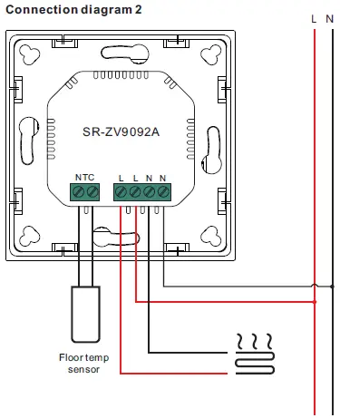
Connection diagram 2
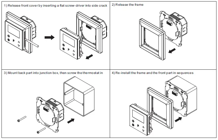
Installation


 Heatit Z-wave Thermostat Heae5430499 Manual")


