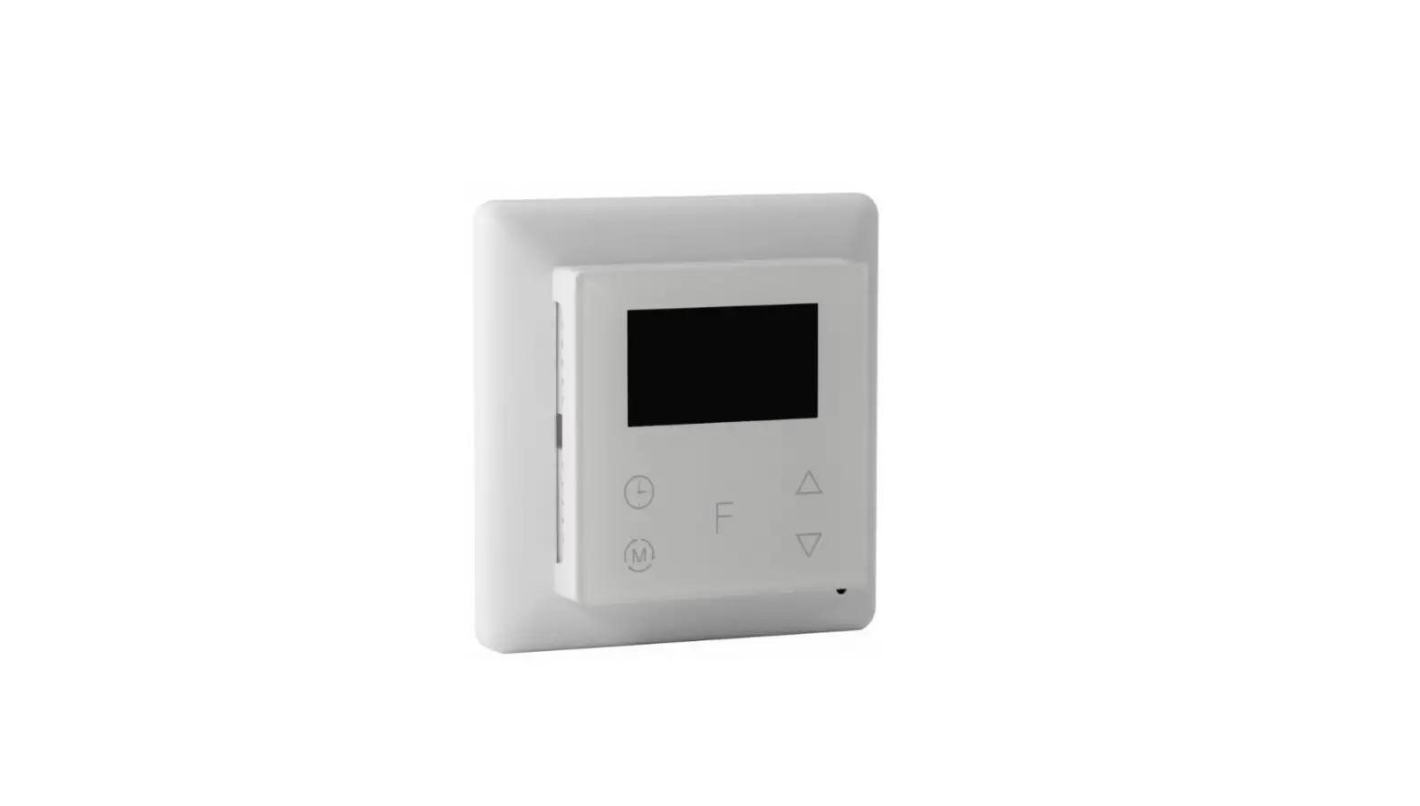
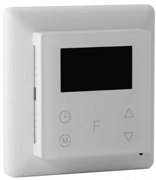
SUNRICHER SR-ZG9092A Zigbee Heating Thermostat
Function introduction
Product Data
| Radio Frequency | 2.4GHz |
| Input Voltage | EU: AC200-240V, 50/60Hz |
| Output Voltage | EU: AC200-240V |
| Max Load | 3680W @ 230V (resistive load) |
| Max Current | 16A |
| Power Consumption | <2W |
| Ambient Temperature | 0°C to 40°C (during operation) |
| Set Temperature Range | 0°C to 40°C |
| Hysteresis | 0.5°C to 2°C (default 0.5°C) |
| Floor sensor type | 1. NTC/10K B(25/50℃)=3950 (default) 2. NTC/15K B(25/50℃)=3950 3. NTC/50K B(25/50℃)=3950 4. NTC/100K B(25/50℃)=3950 5. NTC/12K B(25/50℃)=3950 |
| Control Mode | OFF, HEAT, ENERGY HEAT, AWAY, DRY |
| Control Type | Control type means which temperature sensor the device refers to when it adjust temperature. Room sensor: adjust temperature refers to room temperature (factory default type). Floor sensor: adjust temperature refers to floor temperature. Room+Floor sensor: adjust temperature refers to both room temperature and floor temperature. |
| Wiring Requirement | Current ≤ 13A – 1.5mm² wire Current > 13A to 16A – 2.5mm² wire |
| IP Rating | IP21 |
| Control Pollution Degree (Method D) | pollution degree 2 |
| Rated Impulse Voltage (Method D) | 4kV |
| Relative Humidity | 8% to 80% |
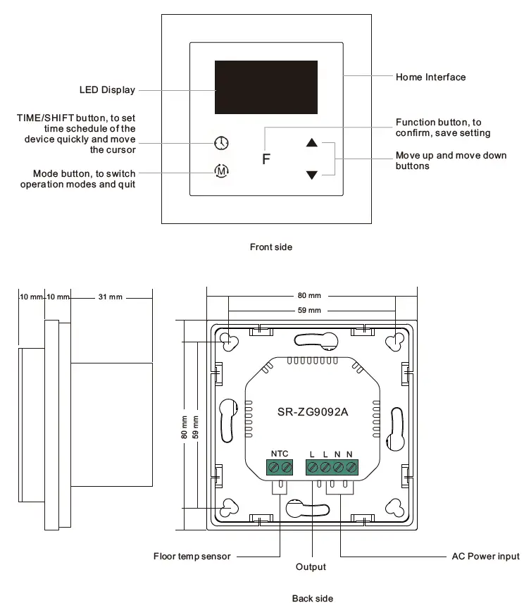
| Dimensions | 80x80x52mm |
|
Approvals | CE, LVD: EN 60730-1:2016;A1, EN IEC 60730-2-9:2019;A1 EMC & RF: EN IEC 61000-3-2:2019, EN 61000-3-3:2013+A1:2019, EN 60730-1:2016+A1:2019, EN 60730-2- 19:2019+A1:2019+A2:2020, EN 50663:2017;ETSI EN 301 489- 1V2.2.3, ETSI EN301 489-3V2.1.1 ETSI EN300 220-1 v3.1.1., ETSI EN300 220-2 V3.2.1 RED certificate: 2014/53/EU |
- The Zigbee HVAC controller is a wireless thermostat for heating system, which complies to Zigbee 3.0 wireless protocol standards. The thermostat has 4 operation modes which can be controlled manually and locally or through remote controlled through Zigbee gateway controller.
- All setup is performed via supported IEEE 802.15.4-based control platforms and other Zigbee3.0 compatible control systems. Appropriate gateway control software allows for adjustment of control mode, control type, schedule etc.
- Sensors: Air temperature
- THERMOSTAT MODE: OFF, HEAT, ENERGY HEAT, AWAY, DRY
- Measurement range: –10°C to +60°C
- Accuracy: ±0.1°C
- WARNING: Electrical power must be switched off during installation
Home Interface
Home Interface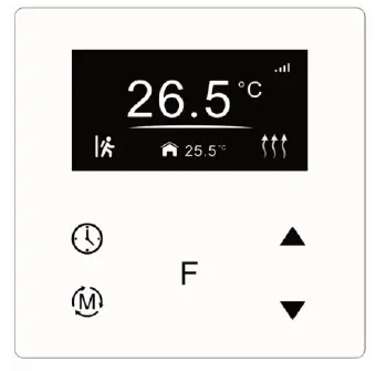
- Already added to a Zigbee network:

- Child Lock enabled:

- Week display: MON, TUE, WED, THU, FRI, SAT, SUN
- The set temperature: Set 28.5℃
- Room temperature:
 25.5℃
25.5℃ - Floor temperature:

- Operation modes:
 ( AWAY),
  (Automatic),
  (Manual),
  (Drying) ,
  (OFF), Heating status:
 (Heating),
  (Locked: heating forbidden),
  (Door is opened, heating forbidden)
Button Description
 : TIME/SHIFT button, to set time schedule of the device quickly and move down the cursor
 : Function button, to confirm, save setting
 : Mode button, to switch operation modes and quit
 : Move up and move down buttons
Standby Interface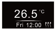
If there is no operation within 2 minutes, the device will go to this standby interface.
Once the device goes to standby interface, if there is no operation within 1 minute, the display will go off automatically.
Safety & Warnings
- DO NOT install with power applied to device.
- DO NOT expose the device to moisture.
Basic Function Introduction
Switch Operation modes
Short press![]() button on Home interface to switch operation modes: the icons of Away, Manual (Comfort), Automatic (Energy Save), Drying, OFF modes will be displayed alternatively for 3 seconds and last displayed mode will be selected, or just short press
button on Home interface to switch operation modes: the icons of Away, Manual (Comfort), Automatic (Energy Save), Drying, OFF modes will be displayed alternatively for 3 seconds and last displayed mode will be selected, or just short press![]() button to select a desired mode when the modes’ icon displayed alternatively.Press and hold
button to select a desired mode when the modes’ icon displayed alternatively.Press and hold![]() button on Home interface for over 3 seconds to select Away mode directly, then press and hold
button on Home interface for over 3 seconds to select Away mode directly, then press and hold![]() button for 3 seconds to quit Away mode.
button for 3 seconds to quit Away mode.
- OFF Mode: this mode means that the device is under idle status.
- Manual (Comfort Mode): the device will control the heating system according to current set temperature. The temperature can be set by move up and move down button on the Home interface, or the mode and temperature can be configured by Zigbee gateway.
- Automatic (Energy Save Mode): the device will control the heating system according to the configured time schedule, or the mode can be configured by Zigbee gateway but the temperature can not be modified and sent by the gateway alone.
- Away (Away Mode): this mode means there is no person at home, to keep a certain indoor temperature, the user can set the deadline of away, it also can be considered as anti-freezing function, the recommended setting temperature is 4-10 degrees. The mode and temperature can be configured by Zigbee gateway.
- Drying (Drying Mode): The device will judge the set temperature for heating within a short period of time, or the mode and temperature can be configured by Zigbee gateway.
System Setting Interface
Under Home interface, meanwhile the device is at OFF mode ![]() , press and hold move up and move down buttons
, press and hold move up and move down buttons ![]() at the same time for over 5 seconds to enter into System Setting Interface as follows:
at the same time for over 5 seconds to enter into System Setting Interface as follows:
- Quit: on System Setting Interface short press button to go back to Home interface.
- Enter into set interface of each setting item: short press move up
 or move down
 button to select a setting item, then short press button to enter into set interface of the selected item.
Preview of Device Information
On System Setting Interface, user can enter into![]() PREVIEW interface, the interface will display some basic configurations, energy consumption, date, floor temperature etc.
PREVIEW interface, the interface will display some basic configurations, energy consumption, date, floor temperature etc.
Auto Mode Schedule
When Auto Mode Schedule is valid, the device will control according to the set temperature of the schedule. For instance, if user would like to keep room temperature at 18 degree Celsius during 18:00-23:00 on every Monday, and keep room temperature at 20 degree Celsius after 22:30 on every Monday, then user can set schedule by himself.
Schedule setting method 1: user can enters into![]() schedule on System Setting Interface, the schedule interface is as follows:
schedule on System Setting Interface, the schedule interface is as follows:
Short press button![]() to select “Auto Schedule”, then short press
to select “Auto Schedule”, then short press![]() button to enter into Auto Mode Schedule weekly setting interface.
button to enter into Auto Mode Schedule weekly setting interface.
Schedule setting method 2: on System Setting Interface, meanwhile the device is under Auto Mode ![]() , short press button
, short press button![]() to enter into Auto Mode Schedule weekly setting interface quickly: On Auto Mode Schedule weekly setting interface, use buttons
to enter into Auto Mode Schedule weekly setting interface quickly: On Auto Mode Schedule weekly setting interface, use buttons![]() and
and ![]() to enter into schedule setting of a certain week as follows:
to enter into schedule setting of a certain week as follows: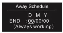
On Auto Day Schedule interface, short press button![]() to select the time or temperature that you would like to modify, then short press move up and move down
to select the time or temperature that you would like to modify, then short press move up and move down ![]() buttons to modify value, then short press button
buttons to modify value, then short press button![]() to save and quit, short pressing button
to save and quit, short pressing button![]() only quits without saving.
only quits without saving.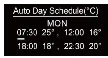
For each schedule, the latter time should be later than the former time, otherwise saving will fail with the error remind “Time setting error!!!”. The default time schedules are as follows: Monday ~ Friday.
- 7:30,24℃ ~ 12:00,20℃
- 18:00,16℃ ~ 22:30,18℃
- Saturday~Sunday
- 7:30,24℃ ~ 12:00,20℃
- 18:00,18℃ ~ 22:30,18℃
Away Mode Schedule
User can set time to leave home and time to go home according to the requirements of themselves, and set how the device will control the temperature during this period.
- If away mode has already been activated, the end time for away mode is valid, the device will execute Away Mode Temperature Schedule before the end time.
- If away mode has already been activated, the values of end time for away mode are set as 0, the device will always execute current set temperature with no time limitation. The device will consider the mode as antifreeze mode, the recommended temperature setting is 4-10℃, and factory default setting is 6℃.
D means date, M means month, Y means year (2019-2099)
Start and end mean away time.
To enter into the setting interface and setting method, please refer to the 1.4 Auto Mode (Energy Save Mode) Schedule.
Dry Mode Schedule
For example, in order to quickly dry the water on the floor of the bathroom, the device can be set to quickly heat in a short time to dry the floor. Enter the configuration interface as follows:
- Duration: set how long the dry mode lasts, can be configured through the proprietary attribute DryTime (0x1006) of Thermostat Cluster (0x0201), the configurable range is 5-100 minutes.
- After Mode: set the mode after the drying mode ends, can be configured through the proprietary attribute ModeAfterDry (0x1007) of Thermostat Cluster (0x0201).
- Remain: shows the remaining time of the drying mode
For configuration method and modification, please refer to Automatic Mode (Energy Save Mode) Schedule: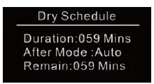
MONITOR SET
The function of monitor set is real time monitor of over current, over heat and freezing, on Home interface, short press MONITOR SET to enter into monitor set interface as follows: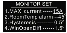
Short press button ![]() to select the item would like to modify, then short press move up and move down
to select the item would like to modify, then short press move up and move down![]() buttons to modify value of selected item, then short press
buttons to modify value of selected item, then short press![]() button to save and quit, short pressing button
button to save and quit, short pressing button![]() only quits without saving.
only quits without saving.
Max Current (16A by default)
If current is over the set value, the relay will be forced to off by the device, and the state will be reported to the gateway. The over current alarm function can be disabled, which can be set directly through the device. Or can be configured through the ACAlarmsMask and ACCurrentOverload of Electrical Measurement (0X0B04), for details please refer to the configuration value.
RoomTemp alarm (45°C by default)
If room temperature is over the set value, the relay will be forced to off by the device, and over heat alarm will be reported to the associated devices, meanwhile the buzzer or vibrator will beep 3 times every 10 seconds. The over heat alarm function can be disabled, which can be set directly through the device. Or can be configured through the attribute AlarmAirTempOverValue (0x2001) of Thermostat Cluster (0x0201), when this value is set as 0, this function is disabled.
Over heat alarm interface is as follow: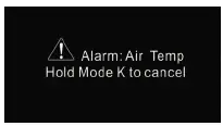
Note: to cancel over current alarm or over heat alarm, just press and hold![]() button for over 3 seconds or reset power of the device. After cancel manually, the relay will show heating forbidden icon
button for over 3 seconds or reset power of the device. After cancel manually, the relay will show heating forbidden icon![]() within 120 seconds, but other operations are allowed.
within 120 seconds, but other operations are allowed.
Hysterersis (0.5°C by default)
To prevent the undulation of sensor temperature when the sensor temperature is approaching the set temperature, which will cause that the controller may keep switching on/off the relay. Here hysterersis enables the controller to control the relay only when the sensor temperature is a little bit lower than the set temperature, this value can be set.
For instance, when hysterersis is set as 0.5 degree, then only when current sensor temperature is 0.5 degree lower than the set temperature, will the controller heat, if the sensor temperature >= set temperature, the controller will not heat.
This value can also be configured through the proprietary attribute Hysterersis (0x100A) of Thermostat Cluster (0x0201).
Note: This hysterersis only valid when the control type is single sensor, please refer to the part Control Type.
Window Open Detect (disabled by default)
Once the device is powered on and stable, referring to the room temperature sensor, if the temperature decreases to the threshold of this setting, the window open mark will be enabled, the relay will be forced to turn off to save energy, then the icon ![]() will appear. After window open mark is enabled, if the temperature increases to the threshold of this setting in 3 minutes, the window open mark will be disabled.
will appear. After window open mark is enabled, if the temperature increases to the threshold of this setting in 3 minutes, the window open mark will be disabled.
Once the window open mark is enabled, it will be disabled after 10 minutes, and the device will keep current working mode.
This value can also be configured through the proprietary attribute WindowOpenCheck (0x1009) of Thermostat Cluster (0x0201), 0 means this function is disabled.
Note: this function will work better when the device is installed beside the window or door.
TIME/DATE SET
Select TIME/DATE on Home Interface to enter into TIME/DATE SET interface as follow:
Short press button![]() to select the item would like to modify, then short press move up and move down
to select the item would like to modify, then short press move up and move down![]() buttons to modify value of selected item, then short press
buttons to modify value of selected item, then short press![]() button to save and quit, short pressing
button to save and quit, short pressing ![]() button only quits without saving.
button only quits without saving.
The device Time Cluster is client, if the bound device supports local time of Time Cluster, the device will acquire local time from the bound device spontaneously under 3 situations: acquire after this device is added to a network, acquire when the device already added to a network and power is reset, acquire every 24 hours .
OTHER SET
Select ![]() OTHER SET on Home Interface to enter into OTHER SET interface as follow:
OTHER SET on Home Interface to enter into OTHER SET interface as follow: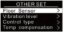
Short press button![]() to select the item would like to modify, then short press move up and move down buttons
to select the item would like to modify, then short press move up and move down buttons![]() to modify value of selected item, then short press button
to modify value of selected item, then short press button![]() to save and quit, short pressing
to save and quit, short pressing![]() button only quits without saving.
button only quits without saving.
Floor Sensor (NTC 10K by default)
If external sensor is broken, the user can buy NTC sensor by themselves, the available sensor types are as follows:
- NTC 100K/25 (3m,NTC,R25=100KΩ±1%@25℃, B25/50=3950K±1%)
- NTC 50K/25 (3m,NTC,R25=50KΩ±1%@25℃, B25/50=3950K±1%)
- NTC 15K/25 (3m,NTC,R25=15KΩ±1%@25℃, B25/50=3950K±1%)
- NTC 10K/25 (3m,NTC,R25=10KΩ±1%@25℃, B25/50=3950K±1%)
- NTC 12K/25 (3m,NTC,R25=12KΩ±1%@25℃, B25/50=3950K±1%)
This sensor type can also be configured through the proprietary attribute FloorSensorType (0x1002) of Thermostat Cluster (0x0201).
Key vibration level (OFF by default)
Set the level of vibration sensor under the buttons or buzzer level.
- OFF: vibration or buzzer off
- Low Level, High Level: low vibration or buzzer level, high vibration or buzzer level This level can also be configured through the proprietary attribute ButtonVibrationLevel (0x1001) of Thermostat Cluster (0x0201).
Control type (Room sensor by default)
Control type means which temperature sensor the device refers to when it adjust temperature.
- Room sensor: adjust temperature refers to room temperature (factory default type)
- Floor sensor: adjust temperature refers to floor temperature
- Room+Floor sensor: adjust temperature refers to both room temperature and floor temperature. Turn on heat valve under other circumstances. This mode is to prevent the device from continuous heating that caused by malfunction of either sensor. When the floor sensor temperature is >= the set temperature minus 1 or when the room sensor is >= the set temperature, either of the conditions is achieved, the controller will stop heat, otherwise the controller will heat.
This control type can also be configured through the proprietary attribute ControlType (0x1003) of Thermostat Cluster (0x0201).
Temp compensation (0 by default)
The displayed temperature may has big tolerance caused by the sensor or other factors, so it is necessary to do temp compensation to room sensor and floor sensor. Compensation range is -5 ~ +5℃, stepping is 0.5℃.
This value can also be configured through the attribute LocalTemperatureCalibration (0x0010) of Thermostat
Cluster (0x0201), and through the proprietary attribute FloorSensorCalibration (0x1005) of Thermostat Cluster (0x0201).
RePower status(last status by default)
Device state after reset power of the device. If set as “last status”, device will go to the status before power failure after power on again. If set as “default”, device will go to default mode after power on again. This status can also be configured through the proprietary attribute PowerUpStatus (0x1004) of Thermostat Cluster (0x0201).
Display Temp type (Home Temp by default)
This parameter defines which sensor temperature will be displayed on Home page.
- Floor Temp: floor temperature (external sensor).
- Home Temp: indoor air temperature.
This status can also be configured through the proprietary attribute TemperatureDisplay (0x1008) of Thermostat Cluster (0x0201).
Operate Brightness (Mid Level by default)
The OLED display brightness when operate the device.
High Level, Mid Level, Low Level.
This brightness can also be configured through the proprietary attribute OperateDisplayLcdBrightness (0x1000) of Thermostat Cluster (0x0201).
Display Auto Off (60S by factory setting)
By factory setting, once the device goes to standby interface, if there is no operation within 1 minute, the display will go off automatically.
Child Lock
On the Home Interface, press and hold both ![]() and
and ![]() buttons for over 10S, the Child Lock can be enabled or disabled, when the Child Lock is enabled, the icon will appear at the upper right corner, otherwise the icon will not appear.
buttons for over 10S, the Child Lock can be enabled or disabled, when the Child Lock is enabled, the icon will appear at the upper right corner, otherwise the icon will not appear.
Internal Over Heat Protection
To ensure the safety of the device, if the internal temperature of the device (not displayed on the interface) is over a certain value during heating process, the device will execute a short temporary action to turn off the relay, and the icon![]() will appear on the interface , after the temperature decreases to a certain value, the device will recover to work.
will appear on the interface , after the temperature decreases to a certain value, the device will recover to work.
Zigbee Configuration Introduction
Select![]() Network Set on Home Interface to enter into Zigbee network management interface as follow:
Network Set on Home Interface to enter into Zigbee network management interface as follow:
Adding to a Zigbee Network
Operate your Zigbee gateway to add device, select “Add”, then short press button![]() , the device will search network and try to join, “Status” will show “Inclusion…”. If there is no response from a gateway, or adding failed, “Status” will show “Fail”. If added successfully, “Status” will show “Inclusion OK” and device ID.
, the device will search network and try to join, “Status” will show “Inclusion…”. If there is no response from a gateway, or adding failed, “Status” will show “Fail”. If added successfully, “Status” will show “Inclusion OK” and device ID.
Removing from a Zigbee Network
Operate your Zigbee gateway to remove device, Select “Remove”, then short press button![]() , the device will send out removing request, “Status” will show “Exclusion…”. If there is no response from a gateway, or removing failed, “Status” will show “Fail”. If removed successfully, “Status” will show “Exclusion OK” and device ID will be showed as 0.
, the device will send out removing request, “Status” will show “Exclusion…”. If there is no response from a gateway, or removing failed, “Status” will show “Fail”. If removed successfully, “Status” will show “Exclusion OK” and device ID will be showed as 0.
The device will be removed from the network and all parameters will be restored to factory default setting, all bindings will be cleared.
Factory Reset (Reset)
Factory resetting will remove the device from Zigbee network and all parameters will be restored to factory default setting, all bindings will be cleared.
Select “Reset”, then short press button![]() , the device will start reset, “Status” will show “Reset…”. If exclusion failed, “Status” will show “Fail”. If reset successfully, “Status” will show “Reset OK”.
, the device will start reset, “Status” will show “Reset…”. If exclusion failed, “Status” will show “Fail”. If reset successfully, “Status” will show “Reset OK”.
Configure Device Operation Mode through Zigbee
Since Zigbee does not have away mode, the attribute Occupancy (occupied or unoccupied) of Thermostat (0x0201) and attribute Occupancy of received OccupancySensing (0x0406) are required to judge whether it is away mode.
- if the device receives other devices’ or the gateway’s report: the Bit 0 of the value of attribute Occupancy (0x0000) of OccupancySensing Cluster (0x0406) is 1, which means occupied, then the operation mode of the thermostat, the attribute SystemMode(0x001c)=0x04(heat) of Thermostat (0x0201), meanwhile the value of attribute Occupancy (0x0002) of Thermostat (0x0201) is 0. It means the Away Mode is activated, and the thermostat UI will display
 .
. - if the gateway send command to modify the attribute SystemMode(0x001c) of Thermostat (0x0201), the thermostat will quit Away Mode. Meanwhile the value of attribute Occupancy (0x0002) of Thermostat (0x0201) is 1.
- The proprietary attribute 0x2002(Manufacturer Code=0x1224) of the cluster 0x0201 can be modified to configure whether it is away mode or at home.
Note: Away Mode uses attribute UnOccupiedHeatingSetpoint to set temperature. Other modes uses attribute OccupiedHeatingSetpoint to set temperature.
Zigbee Interface
The thermostat provides 3 zigbee application endpoints:
| Endpoint | Profile | Application |
| 0(0x00) | 0x0000(ZDP) | ZigBee Device Object (ZDO) – standard management features |
| 1(0x01) | 0x0104(HA) | Device ID is 0x0301(Thermostat ). |
| 2(0x02) | 0x0104(HA) | Device ID is 0x0007(OTA). |
| 242(0xF2) | 0xA1E0(GP) | Device ID is 0x0021(GreenPower). |
Application Endpoint #0 –ZigBee Device Object
- Application profile Id 0x0000
- Application device Id 0x0000
- Supports all mandatory clusters
Application Endpoint #1 –Thermostat
| Cluster | supported | Description |
| 0x0000 | server | Basic Provides basic information about the device, such as the manufacturer ID, vendor and model name, stack profile, ZCL version, production date, hardware revision etc. Allows a factory reset of attributes, without the device leaving the network. |
| 0x0003 | server | Identify Allows to put the endpoint into identify mode. Useful for identifying/locating devices and required for Finding & Binding. |
| 0x0004 | server | Groups Allows adding this endpoint to one or more groups. Afterwards the endpoint can be addressed using the group address. This is also a prerequisite for scenes. You may also query group membership and delete group associations. |
| 0x0005 | server | Scenes Allows storing one or more scenes per group, where each scene consists of a pre-set on/off state value. You may either store the current values as a scene, or provide scene settings when adding a scene, or delete scenes. |
| 0x0201 | server | Thermostat |
| 0x0702 | server | Simple Meter |
| 0x0b04 | server | Electrical Measurement Measuring power, voltage, current |
| 0x0009 | server | Alarm Device related alarm |
| 0x0406 | client | Occupancy Sensing |
| 0x000a | client | Time |
Basic -0x0000 (Server)
- Attributes supported:
Attribute Type Description 0x0000 INT8U, read-only ZCLVersion 0x03 0x0001 INT8U , read-only ApplicationVersion This is the firmware version number of the application 0x0002 INT8U , read-only StackVersion 0x0003 INT8U , read-only HWVersion Hardware version 1 0x0004 string, read-only ManufacturerName “Sunricher” 0x0005 string, read-only ModelIdentifier “Zg9092” 0x0006 string, read-only DateCode NULL 0x0007 ENUM8, read-only PowerSource Device power supply, fixed value 0x01 Mains (single phase) 0x0008 ENUM8, read-only GenericDevice-Class 0XFF 0x0009 ENUM8, read-only GenericDevice-Type 0XFF 0x000A octstr read-only ProductCode 00 0x000B string, read-only ProductURL NULL 0x4000 string, read-only Sw build id 6.9.1.0_r4 - Command supported:
Command Description 0x00 Reset to Factory Defaults Command On receipt of this command, the device resets all the attributes of all its clusters to their factory defaults. Note that networking functionality, bindings, groups, or other persistent data are not affected by this command.
Scenes 0x0005 (Server)
- Attributes supported:
Attribute Type Description 0x0000 int8u, read-only SceneCount Holds the total number of scenes (across all groups) currently stored on the device.
0x0001 int8u, read-only CurrentScene If the SceneValid attribute is true, this attribute, together with the CurrentGroup attribute,indicates the currently active scene.
0x0002 int16u, read-only CurrentGroup If the SceneValid attribute is true, this attribute, together with the CurrentScene attribute,indicates the currently active scene.
0x0003 bool, read-only SceneValid If true, the scene identified by CurrentGroup and CurrentScene is currently active, i.e. all device attribute values match the values in the scene field set.
0x0004 bitmap8 , read-only NameSupport - Command supported:
Command Description 0x00 Add Scene Adds a scene with or without a scene field set
0x01 View Scene Returns the scene field set, name and transition times for a scene.
0x02 Remove Scene Removes a scene from the scene table.
0x03 Remove All Scenes Removes all scenes that belong to a particular group.
0x04 Store Scene Stores the device’s current state as a scene or updates a previously stored scene accordingly
0x05 Recall Scene Reverts the device’s current state using the values from the previously stored field set.
Groups-0x0004 (Server)
- Attributes supported:
Attribute Type Description 0x0000 bitmap8, read-only NameSupport 0, not supported - Command supported:
Command Description 0x00 Add Group Adds the endpoint to a group.
0x01 View Group Determines whether the device belongs to a group and returns the group name, if supported
0x03 Remove Group Removes this endpoint from the specified group. Also removes all scenes that refer to this group.
0x04 Remove All Groups Removes this endpoint from all groups. Also removes all scenes that refer to any of the existing groups.
0x05 Add Group if Identifying Adds this endpoint to the group, if the endpoint is identifying.
Thermostat-0x0201(Server)
- Attributes supported:
Attribute Type Description 0x0000 int16S , read-only reportable LocalTemperature Attribute This is room temperature, the maximum resolution this format allows is 0.01 ºC.
0x0001 int16S , read-only reportable OutdoorTemperature This is floor temperature, the maximum resolution this format allows is 0.01 ºC.
0x0002 bitmap8 , read-only Occupancy When this flag is set as 1, it means occupied, OccupiedHeatingSetpoint will be used, otherwise UnoccupiedHeatingSetpoint will be used.
0x0010 Int8S , reportable LocalTemperatureCalibration Room temperature calibration, range is -30-30, the maximum resolution this format allows 0.1°C. Default value: 0
0x0011 int16S , reportable OccupiedCoolingSetpoint This system is not invalid.
0x0012 int16S , reportable
OccupiedHeatingSetpoint Range is 0-4000,the maximum resolution this format allows is 0.01 ºC. Default is 0xbb8(30.00ºC)
0x0014 int16S , reportable UnoccupiedHeatingSetpoint Range is 0-4000,the maximum resolution this format allows is 0.01 ºC. Default is 0x258(6.00ºC)
0x001B Enum8, reportable ControlSequenceOfOperation Set device supported operation type, here only supports Heating Only(0x02)
0x0029 Map16, read-only, reportable
HVAC relay state/ ThermostatRunningState Indicates the relay on/off status, here only supports bit0( Heat State)
- Proprietary Attributes:
Attribute Type Manufacturer code Description 0x1000 ENUM8, reportable
0x1224 OperateDisplayLcdBrightnesss OLED brightness when operate the buttons: Value=0 : Low Level
Value=1 : Mid Level(default) Value=2 : High Level
0x1001 ENUM8 reportable
0x1224 ButtonVibrationLevel Key beep volume & vibration level: Value=0 : off(default)
Value=1 : Low Level Value=2 : High Level
0x1002 ENUM8 reportable
0x1224 FloorSenserType Select external (Floor) sensor type: Value=5 : NTC 12K/25
Value=4 : NTC 100K/25 Value=3 : NTC 50K/25 Value=2 : NTC 15K/25
Value=1 : NTC 10K/25 (Default)
0x1003 ENUM8 reportable
0x1224 ControlType The referring sensor for heat control: Value=0 : Room sensor(Default) Value=1 : floor sensor
Value=2 : Room+floor sensor
0x1004 ENUM8 reportable
0x1224 PowerUpStatus The mode after reset power of the device: Value=0 : default mode
Value=1 : last status before power off (Default)
0x1005 INT8S, reportable
0x1224 FloorSenserCalibration The temp compensation for the external (floor) sensor, range is -30-30, unit is 0.1°C. default value 0
0x1006 INT8U reportable
0x1224 DryTime The duration of Dry Mode, range is 5-100, unit is min. Default value is 5.
0x1007 ENUM8 reportable
0x1224 ModeAfterDry The mode after Dry Mode: Value=0 : OFF
Value=1 : Manual mode
Value=2 : Auto mode –schedule (default) Value=3 : Away mode
0x1008 ENUM8 reportable
0x1224 TemperatureDisplay : Value=0 : Room Temp (Default) Value=1 : Floor Temp
0x1009 INT8U reportable
0x1224 WindowOpenCheck The threshold to detect open window, range is 0.3-8, unit is 0.5ºC,
0 means disabled, default is 0
0x100A INT8U reportable
0x1224 Hysterersis Hysterersis setting, range is 5-20, unit is 0.1ºC, default value is 5
0x2001 INT8U, reportable
0x1224 AlarmAirTempOverValue Room temp alarm threshold, range is 0.20-60, unit is 1ºC, 0 means disabled, default is 45
0x2002 ENUM8 reportable
0x1224 Away Mode Set: Value=0: not away (default) Value=1: away
- Command supported:
Command Description 0x0000 Setpoint Raise/Lower Increase or decrease the set temperature according to current mode, unit is 0.1ºC
Simple Meter-0x0702 (Server)
- Attributes supported:
Attribute Type Description 0x0000 unsigned48 , read-only, reportable CurrentSummationDelivered Indicates the current amount of electrical energy delivered to the load.
0x0200 bitmap8 , read-only Status Flags indicating current device status, always is 0x00
0x0300 enum8 , read-only UnitOfMeasure The unit of metering data, this is always kWh(0x00)
0x0303 map8 , read-only SummationFormatting The decimal point on the left and right sides of the data, this is always 0x00
0x0306 bitmap8, read-only MeteringDeviceType Metering data type, this is always Electric Metering (0x00)
Electrical Measurement-0x0b04(Server)
- Attributes supported:
Attribute Type Description 0x0000 bitmap32 , read-only MeasurementType Indicates the physical entities that this devices is able to measure. Supports only bit0: Active measurement (AC)
0x0505 int16U , read-only, reportable RMSVoltage Single phase valid voltage, unit is V
0x0508 int16U , reportable, read-only RMSCurrent Single phase valid current, unit is A
0x050B int16S , reportable read-only ActivePower Single phase valid power, unit is W
0x0600 int16U, read-only ACVoltageMultiplier 0x0601 int16U, read-only ACVoltageDivisor Used together with above attributes, the real displayed voltage = RMSVoltage* ACVoltageMultiplier
/ ACVoltageDivisor
0x0602 int16U, read-only ACCurrentMultiplier 0x0603 int16U, read-only ACCurrentDivisor Used together with above attributes, the real displayed current = RMSCurrent
* ACCurrentMultiplier
/ ACCurrentDivisor
0x0800 int16U, ACAlarmsMask Specifies which configurable alarms may be generated, only
Bit1: Current Overload is set, if set=0, then ACCurrentOverload=0, over current will not be detected
0x0802 int16S , reportable read-only ACCurrentOverload Alarms when the current is over a certain value, 0, 10-16, unit is A
- Proprietary Attributes:
Attribute Type Manufacturer code Description 0x0000 Int8u, reportable 0x1224 OverCurrent Over current value set by the user, range is 0, 10-16, ACCurrentOverload will change spontaneously if this value is modified.
Alarm-0x0009(Server)
Please set a valid value for ACAlarmsMask of Electrical Measurement. The Alarm Server cluster can generate the following commands:
| CmdID | Description |
| 0x00 | Alarm: |
The alarm code of Electrical Measurement is 0, Proprietary command, Manufacturer code=0x1224
| CmdID | Description |
| 0x00 | Room air temperature over heat, not alarm code |
Time-0x000A(client)
The Time cluster is a general cluster for time it is based on a UTC time in seconds since 0 hrs 0 mins 0 sec on 1st January 2000. Refer to [Z2] for ZigBee specification of the time cluster. The metering device will use this clusters as a client – provided that a suitable Time Server is available on the network (most likely on the Gateway/concentrator) If the device has bound TIME cluster, then the device will acquire the value of Local Time (0x0007) spontaneously.
OccupancySensing-0x0406(client)
The attributes that can be received:
| Attribute | Type | Description |
| 0x0000 | bitmap8 , | Occupancy Bit 0 specifies the sensed occupancy as follows: 1 = occupied, 0 = unoccupied. This flag bit will affect the Occupancy attribute of HVAC cluster, and the operation mode. |
Application Endpoint #2–OTA
| Cluster | supported | Description |
| 0x0000 | server | Basic |
| 0x0003 | server | Identify |
| 0x0019 | Client | OTA Upgrade Pull-oriented firmware upgrade. Searches the network for mating servers and allows the server to control all stages of the upgrade process, including which image to download, when to download, at what rate and when to install the downloaded image. |
Ota complies to standard Zigbee protocol.
Application Endpoint #242 –GreenPower
Troubleshooting:
- External (floor) sensor temperature tolerance is too high Possible reason: the selected sensor type is not correct
- The gateway can not set temperature when energy save mode is selected The temperature schedule of auto mode (energy save mode) is not configured correctly
- Current temperature is not executed when away mode is selected Check whether away mode time is set as 0 or within valid time range
- Over heat alarm when power on the device Possible reason: the set sensor type is not correct or sensor type after factory reset is not correct
- Device time is not the same as the gateway controller after added to the network Set the device time and time zone manually after added to the gateway network
- The tolerance of the indoor temperature sensor is high after powered on Possible reason: due to temperature effect, we need to wait for a while
Wiring diagram
This device should be installed by a licensed electrician in a manner that conforms to local regulations and building codes. Provide these instructions to the licensed electrician who is installing the device.
WARNING: Electrical power must be switched off during installation.
- Placement of the device is of utmost importance for proper operation and must be away from sunlight and sources of direct heat. We recommend installing the device approximately 1.5 meters above the floor.
- Remove the display unit and backplate of the device from the packaging.
- FIRST ENSURE THE POWER IS OFF at the main circuit breaker, and then test the wires with a probe or multimeter to verify.
Insert the power and heater wires to the correct device terminals by inserting a small Phillips-head screwdriver in the slot beneath each terminal to open. Follow the connection diagram and instructions below:
- Power wires: connect Line & Neutral wires to L & N terminals labeled “IN”
- Heater wires: connect Line & Neutral wires to L & N terminals labeled with “heating element” graphic
WARNING: The wire size shall be in compliance with regulations, using wire with insufficient size for big load will cause severe temperature rising.
Connection diagram 1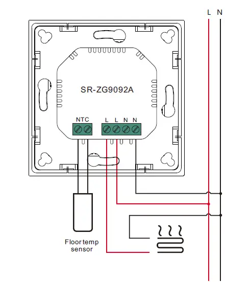
Connection diagram 2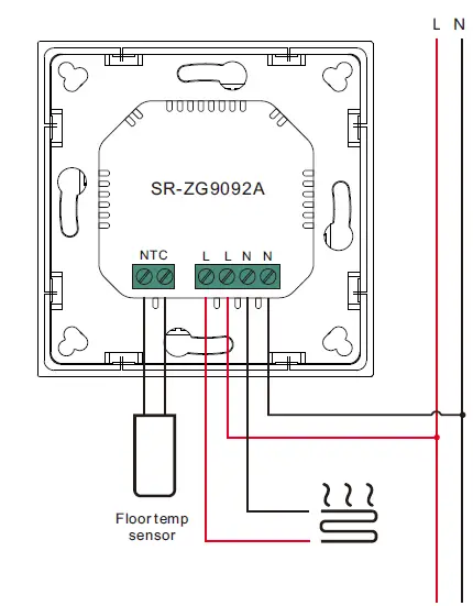
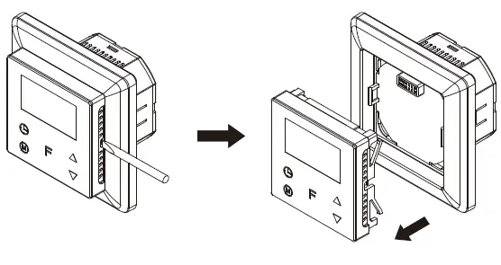
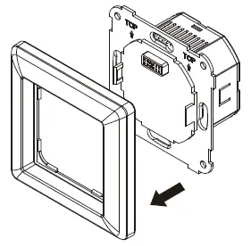
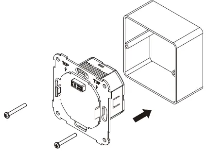
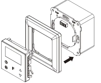
Installation
- Release front cover by inserting a flat screw-driver into side crack

- Release the frame

- Mount back part into junction box, then screw the thermostat in

- Re-install the frame and the front part in sequences