![]() ANC-6000
ANC-6000
Audio Network Controller Board
Installation Instructions
Module Mounting Locations
The ANC-6000 Audio Network Controller board is mounted in the center position over the FX-6000MNS-CH main fire alarm board as shown in Figure 1. If a TNC-5000 Telephone Controller board is used, it is mounted over the ANC-6000.
Figure 1 Mechanical Installation for the ANC-6000 Audio Network Controller Board
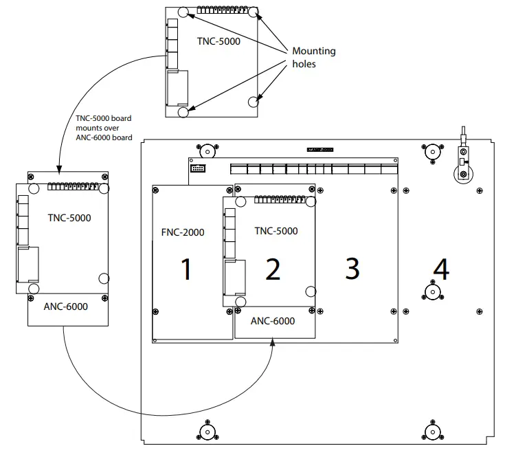
Figure 2 ANC-6000 Audio Network Controller Board Layout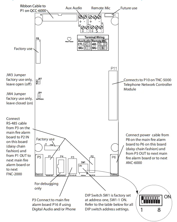 DIP Switch Settings for SW1 on the ANC-6000 Board
Addresses available for the ANC-6000 (per node) are set as noted in the following table.
ANC-6000 Address Setting (DIP SWITCH SW1)
|
ANC-6000
| ADDR | SW1-1 | SW1-2 | SW1-3 | SW1-4 | SW1-5 | SW1-6 | SW1-7 | SW1-8 |
| 1 | ON | OFF | OFF | OFF | OFF | OFF | OFF | OFF | |
| 2 | OFF | ON | OFF | OFF | OFF | OFF | OFF | OFF | |
| 3 | ON | ON | OFF | OFF | OFF | OFF | OFF | OFF | |
| 4 | OFF | OFF | OFF | OFF | OFF | ON | OFF | OFF | |
| 5 | OFF | OFF | OFF | OFF | OFF | ON | OFF | ON | |
| 6 | OFF | OFF | OFF | OFF | OFF | ON | ON | OFF | |
| 7 | OFF | OFF | OFF | OFF | OFF | ON | ON | ON |
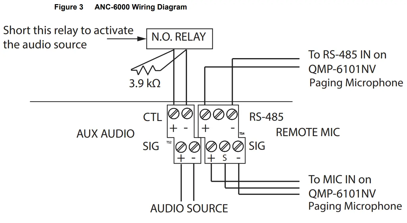
ANC-6000 Wiring
The auxiliary audio input has a maximum input of 1 VRMS. The transformer is isolated on the ANC-6000.
Connect an audio source, for example background music or paging, to the SIG terminal. Connect a normally open relay and 3.9 kΩ resistor to the CTL terminal as shown in Figure 3. Short the relay to activate the auxiliary audio.
LT-6685 Rev 0 Nov 2022 Page 3 of 3
![]()


