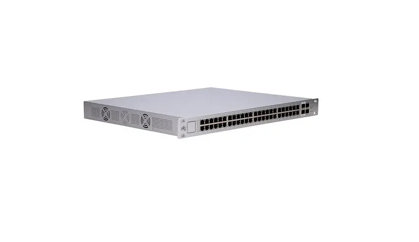
UniFi Switch US-48-500W Instruction Manual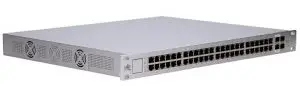
Contents
- UniFi Switch
- Power Cord
- Mounting Screws (Qty. 4)
- Cage Nuts (Qty. 4)
Installation Requirements
- Phillips screwdriver
- Standard-sized, 19″ wide rack with a minimum of 1U height available
- For indoor applications, use Category 5 (or above) UTP cabling approved for indoor use.
- For outdoor applications, shielded Category 5 (or above) cabling should be used for all wired Ethernet connections and should be grounded through the AC ground of the power supply. We recommend that you protect your networks from harmful outdoor environments and destructive ESD events with industrial-grade, shielded Ethernet cable from Ubiquiti. For more details, visit: ui.com/toughcable
 Note: Although the cabling can be located outdoors, the UniFi Switch itself should be housed inside a protective enclosure.
 IMPORTANT: We strongly recommend using UPS backup and power regulation to prevent equipment damage due to stability issues with local AC power.
System Requirements
- Linux, Mac OS X, or Microsoft Windows 7/8/10
- Java Runtime Environment 1.6 (1.8 or newer recommended)
- Web Browser: Mozilla Firefox, Google Chrome, Microsoft Edge, or Microsoft Internet Explorer 11
- UniFi Controller v5.4.x or higher
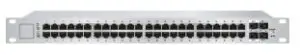
Hardware Overview
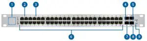
| 1. System LED | |
| Click here for detailed descriptions. | |
| 2. RJ45 PoE LED (Ports 1 – 48) | |
| Off | No PoE |
| Amber | IEEE 802.3af/802.3at |
| Green | 24V Passive PoE |
| 3. RJ45 Speed/Link/Act LED (Ports 1 – 48) | |
| Off | No Link |
| Amber | Link Established at 10/100 Mbps Flashing Indicates Activity |
| Green | Link Established at 1000 Mbps Flashing Indicates Activity |
| 4. SFP+ Speed/Link/Act LED (Ports 1 – 2) | |
| Off | No Link |
| Green | Link Established at 1 Gbps Flashing Indicates Activity |
| White | Link Established at 10 Gbps Flashing Indicates Activity |
| 5. SFP Speed/Link/Act LED (Ports 1 – 2) | |
| Off | No Link |
| Green | Link Established at 1 Gbps Flashing Indicates Activity |
| 6. RJ45 (Ports 1 – 48) | |
| RJ45 ports support Power over Ethernet (PoE) and 10/100/1000 Ethernet connections | |
| 7. SFP+ (Ports 1 – 2) | |
| Hot-swappable SFP+ ports support 1/10 Gbps connections. | |
| 8. SFP (Ports 1 – 2) | |
| Hot-swappable SFP ports support 1 Gbps connections | |
| 9. Reset Button | |
This button serves two functions for the UniFi Switch:
| |
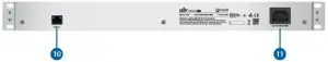
| 10. Console Port |
RJ45 serial console port for Command Line Interface (CLI) management. Use an RJ45-toDB9, serial console cable, also known as a rollover cable, to connect the Console port to your computer. Then configure the following settings as needed:
|
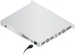
| 11. Power Port |
| Connect the included Power Cord to the Power port. |
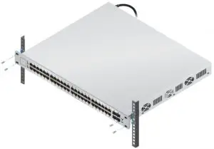
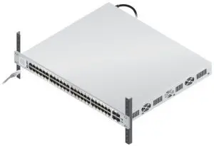
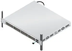
Hardware Installation
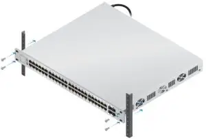
OR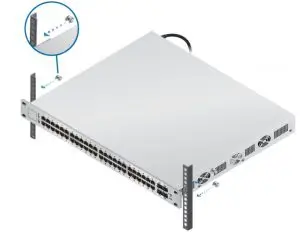
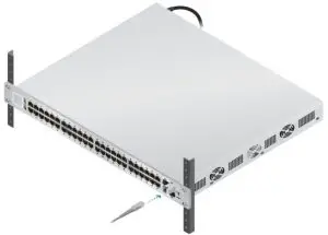
- Connecting Ethernet
Using SFP+ and SFP Ports
| Ports | SFP+ Module Type | SFP Module Type |
| SFP+ 1-2 | 10 Gbps | 1 Gbps |
| SFP 1-2 | (Not supported) | 1 Gbps |

For information about compatible fiber SFP modules, visit: community.ubnt.com/unifi.
Software Installation
Download and install the latest version of the UniFi Controller software at ui.com/download/unifi and follow the on-screen instructions.Note: If you already have UniFi Controller v5.4.x or higher installed, go to the section, Adopting the UniFi Switch.
After you have installed the software and run the UniFi Installation Wizard, a login screen will appear for the UniFi Controller management interface. Enter the username and password that you created and click Sign In.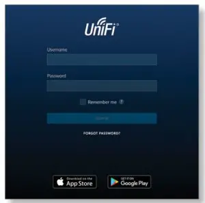
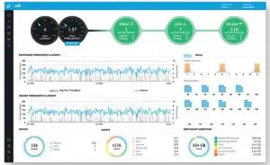
You can manage your network and view network statistics using the UniFi Controller management interface.
To adopt the UniFi Switch, proceed to the section, Adopting the UniFi Switch. For information on configuring and using the UniFi Controller software, refer to the User Guide on the website: ui.com/download/unifi
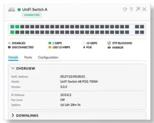
Adopting the UniFi Switch
- From the UniFi Controller dashboard, click Devices in the left menu bar.
- Locate the UniFi Switch in the list of devices under the Model column. Click Adopt.
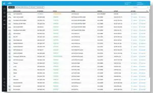
- The System LED on the UniFi Switch will turn blue to confirm that it has been successfully adopted.
Configuring PoE Settings
- On the Devices screen, locate the UniFi Switch. Click the switch to access its settings.
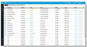
- Click the Ports tab.
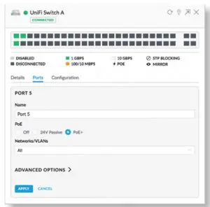
- Click Actions for the port you want to configure.
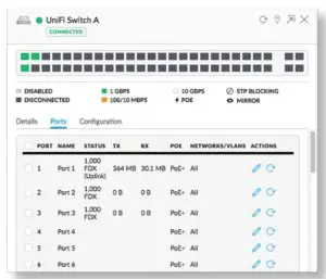
- Select the appropriate PoE setting: Off, 24V Passive, or PoE+. Then click Apply.
For more information, refer to the User Guide on the website: ui.com/download/unifi
Specifications
US-48-500W/US-48-750W | |
| Dimensions | 485 x 43.7 x 374.6 mm (19.09 x 1.72 x 14.75″) |
| Weight US-48-500W | 6.1 kg (13.5 lb) 6.5 kg (14.3 lb) |
| Total Non-Blocking Line Rate | 70 Gbps |
| Max. Power Consumption US-48-500WUS-48-750W | 500W 750W |
| Power Method | 100-240VAC/50-60 Hz, Universal Input |
| Power Supply US-48-500W US-48-750W | AC/DC, Internal, 500W DC |
| Rack-Mount | Yes, 1U High |
| ESD/EMP Protection | Air: ± 24 kV, Contact: ± 24 kV |
| Shock and Vibration | ETSI300-019-1.4 Standard |
| LEDs Per Port RJ45 Data PortsSFP+/SFP Data Ports | PoE, Speed/Link/Activity Speed/Link/Activity |
| Interfaces Networking
Management | (48) 10/100/1000 Mbps RJ45 Ethernet Ports (2) 1/10 Gbps SFP+ Ethernet Ports (2) 1 Gbps SFP Ethernet Ports (1) RJ45 Serial Port Out-of-Band, Ethernet In-Band |
| Operating Temperature | -5 to 40° C (23 to 104° F) |
| Operating Humidity | 5 to 95% Noncondensing |
| Certifications | CE, FCC, IC |
PoE Per Port | |
| PoE Interfaces | POE+ IEEE 802.3af/at (Pins 1, 2+; 3, 6-) |
| Max. PoE+ Wattage per Port by PSE | 34.2W |
| Voltage Range 802.3at Mode | 50-57V |
Safety Notices
- Read, follow, and keep these instructions.
- Heed all warnings.
- Only use attachments/accessories specified by the manufacturer.
 WARNING: Failure to provide proper ventilation may cause fire hazard. Keep at least 20 mm of clearance next to the ventilation holes for adequate airflow. WARNING: To reduce the risk of fire or electric shock, do not expose this product to rain or moisture. WARNING: Do not use this product in location that can be submerged by water. WARNING: Avoid using this product during an electrical storm. There may be a remote risk of electric shock from lightning.
Electrical Safety Information
- Compliance is required with respect to voltage, frequency, and current requirements indicated on the manufacturer’s label. Connection to a different power source than those specified may result in improper operation, damage to the equipment or pose a fire hazard if the limitations are not followed.
- There are no operator serviceable parts inside this equipment. Service should be provided only by a qualified service technician.
- This equipment is provided with a detachable power cord which has an integral safety ground wire intended for connection to a grounded safety outlet.
- Do not substitute the power cord with one that is not the provided approved type. Never use an adapter plug to connect to a 2-wire outlet as this will defeat the continuity of the grounding wire.
- The equipment requires the use of the ground wire as a part of the safety certification, modification or misuse can provide a shock hazard that can result in serious injury or death.
- Contact a qualified electrician or the manufacturer if there are questions about the installation prior to connecting the equipment.
- Protective earthing is provided by Listed AC adapter. Building installation shall provide appropriate short-circuit backup protection.
- Protective bonding must be installed in accordance with local national wiring rules and regulations.
Limited Warranty
ui.com/support/warranty
The limited warranty requires the use of arbitration to resolve disputes on an individual basis, and, where applicable, specify arbitration instead of jury trials or class actions.
Compliance
FCC
Changes or modifications not expressly approved by the party responsible for compliance could void the user’s authority to operate the equipment. This device complies with Part 15 of the FCC Rules. Operation is subject to the following two conditions.
- This device may not cause harmful interference, and
- This device must accept any interference received, including interference that may cause undesired operation.
This equipment has been tested and found to comply with the limits for a Class A digital device, pursuant to Part 15 of the FCC Rules. These limits are designed to provide reasonable protection against harmful interference when the equipment is operated in a commercial environment. This equipment generates, uses, and can radiate radio frequency energy and, if not installed and used in accordance with the instruction manual, may cause harmful interference to radio communications. Operations of this equipment in a residential area is likely to cause harmful interference in which case the user will be required to correct the interference at his own expense.
ISED Canada
CAN ICES-3(A)/NMB-3(A)
Australia and New Zealand
 Warning: This equipment is compliant with Class A of CISPR 32. In a residential environment this equipment may cause radio interference.
CE Marking
CE marking on this product represents the product is in compliance with all directives that are applicable to it.
WEEE Compliance Statement
Declaration of Conformity
Online Resources