![]()
Linear Suspended
ModiFly Patterns
System Overview
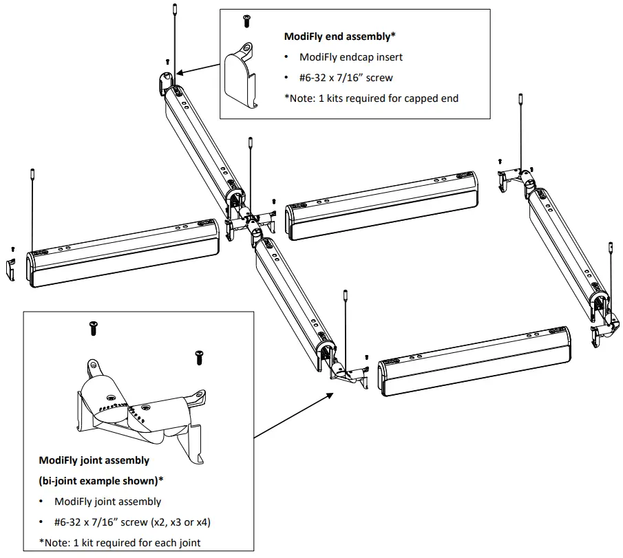
![]() These instructions review how to install ModiFly suspended fixtures in a pattern. The graphic below shows the components required to install a sample pattern of ModiFly suspended fixtures.
These instructions review how to install ModiFly suspended fixtures in a pattern. The graphic below shows the components required to install a sample pattern of ModiFly suspended fixtures.
TOOLS REQUIRED: Phillips screwdriver, Flat-head screwdriver, #2 Robertson screwdriver (optional)
This equipment has been tested and found to comply with the limits for a Class A digital device, pursuant to part 15 of the FCC Rules. These limits are designed to provide reasonable protection against harmful interreference when the equipment is operated in a commercial environment. This equipment generates, uses, and can radiate radio frequency energy and, if not installed and used in accordance with the instruction manual, may cause harmful interference to radio communications. Operation of this equipment in a residential area is likely to cause harmful interference in which case the user will be required to correct the interference at his own expense.
![]() Warning! Shock Hazard!
Warning! Shock Hazard!![]() IMPORTANT: Disconnect or turn ofpower before attempting any installation, service ormaintenance.
IMPORTANT: Disconnect or turn ofpower before attempting any installation, service ormaintenance.![]() Warning! Shock Hazard!
Warning! Shock Hazard!![]() Fixture must be connected to building ground via the provided ground wire before re-connecting to mains power supply.
Fixture must be connected to building ground via the provided ground wire before re-connecting to mains power supply.
![]() Installation Notes
Installation Notes
Arrange boxed fixtures on floor in specified mounting locations, based on supplied layout drawings. Remove fixtures from boxes.
Install all ceiling mounting components and vertical aircraft cables using separate installation instruction for Aircraft Cable Mounting (supplied).
![]() ATTENTION: Install in accordance with local and national building and electric codes.
ATTENTION: Install in accordance with local and national building and electric codes.
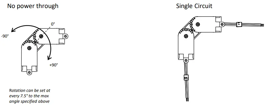
Module Joint Mounting Points
ModiFly patterns come in Bi-, Tri- and Quad- Links.
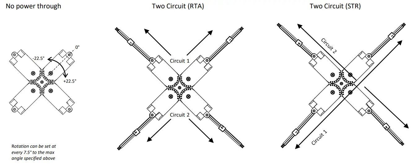
The different configurations and power options are shown below.
Bi-link
Tri-link
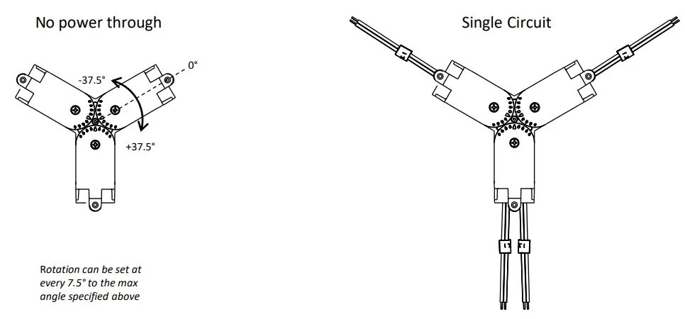
Quad-link
1 Prepare fixtures/install ceiling mounting components
Arrange boxed fixtures on floor in specified mounting locations.
Remove fixtures from boxes. Install all ceiling mounting components and grippers using separate installation instructions for Mounting (supplied).
NOTE: If conditions are dusty/dirty, recommended practice is to leave fixtures in their plastic bags until ready to remove top cap for wiring.

IMPORTANT!!!
AVOID HANDLING THE LIGHT GUIDES WITHOUT WEARING CLEAN GLOVES.
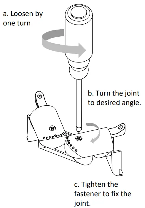
2 Set joint angles
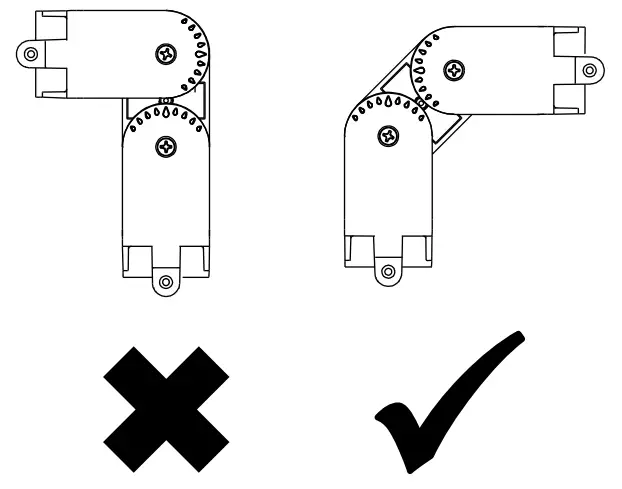
IMPORTANT!!!
When possible, joints shall be rotated at the same amount to form an angle. Example for a right angle:
Set the joint angles as required.
IMPORTANT: Do not over-tighten joiner screws. Ledalite recommends tightening by hand.
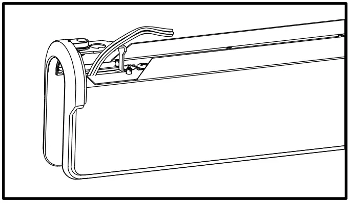
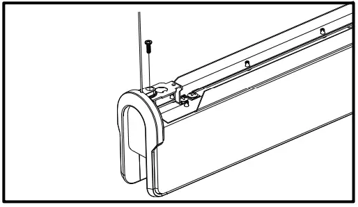
3 Remove top cap
Remove screws along top of fixture with a Phillips or Robertson screwdriver and remove the top cap with the help of a flat head screwdriver.
Repeat this for all fixtures prior to mounting.
4 Feed wires into fixture
Feed wires into the fixture on both ends of the fixture. Do this for all fixtures on joining ends.
Note: Not required for wires at the ends of the run.
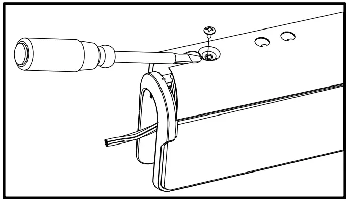
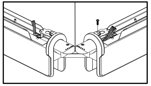
5a Attach joints to starting module
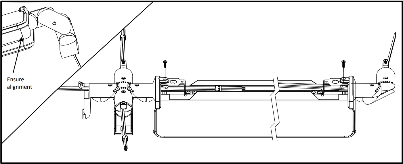
Attach joints on starting module (on both ends if applicable).
Feed joint wire into fixture and secure joints with supplied hardware and a Phillips screwdriver.
Ensure joint is seated properly in the fixture.
Make power connections with supplied quick-wire connectors.
IMPORTANT: Do not over-tighten joiner screws. Ledalite recommends tightening by hand.
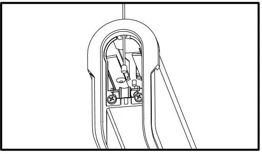
5b Make electrical connections – tri-link details [if applicable]
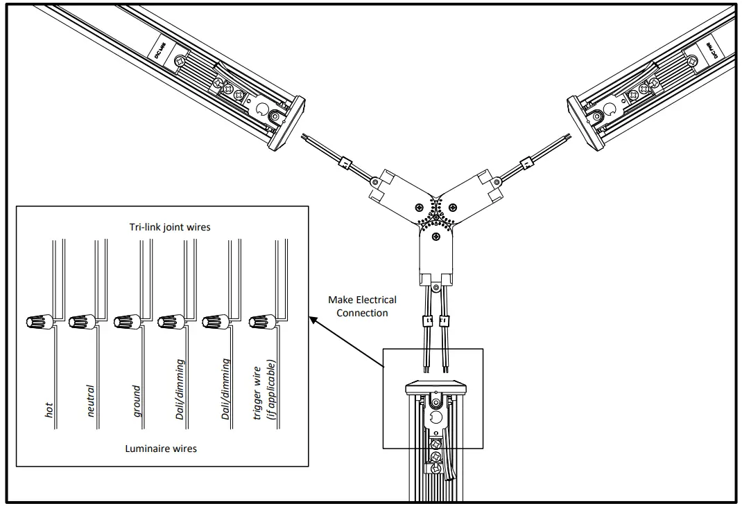
For the tri-link joint leg with two feeds, connect both to the luminaire module to form one circuit.
6 Mount remaining joints to gripper
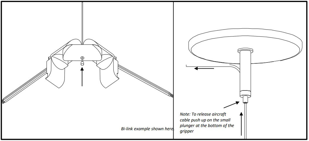
Insert aircraft cable through the joints and mount them in appropriate locations as supplied by layout drawing.
Mount the joints by feeding the aircraft cable through the gripper at the ceiling.
IMPORTANT: Mount all joints to roughly the same height – fine tune levelling can be done as a final step.
7 Mount starting module
Mount the starting module to the grippers at the same level as the joints mounted in the previous step.
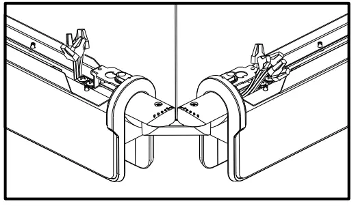
8 Connect module(s)
With two people, mount the next module on both sides. Feed joint wires into fixture and secure with screw provided in joint kit with a Phillips screwdriver.
Repeat for all modules in the pattern.
IMPORTANT: Do not over-tighten joiner screws. Ledalite recommends tightening by hand.
9 Mount ends (if applicable)
For patterns with end of run modules, Insert aircraft cable into diecast cross plate.
With two people, mount to ceiling gripper.
10 Complete electrical connections power drop
Remove ½” knockouts as required. Make power drop connection and tuck wires into fixture cavity.
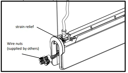
11 Complete electrical connections – in run
Complete in-row electrical connections
For non power drop locations use either supplied quick-wire connectors or wire nuts supplied by others.
For non-power through joints/ends (if applicable), cap all wires and tuck into wire cavity.
12 Close with endcaps (if applicable)
Cap all wires if no power drop connection is made and tuck into fixture. Secure endcaps with screw provided with a Phillips screwdriver.
IMPORTANT: Do not over-tighten endcap screws. Ledalite recommends tightening by hand.
13 Secure top cap
Tuck all wires into fixture then replace top caps and secure with screws provided with either a Robertson #2 screwdriver or a Phillips screwdriver.
14 Leveling and cleanup
- Level row by adjustments at the gripper (see step 6).
- Wipe light guide panel clean if required – ensuring to not introduce scratches.
Sensors in Rows
Single Sensor Controlling Whole Row
- Purple & brown (or purple & grey/pink) control wires MUST be connected between fixtures.
Note:
• A maximum of 8 drivers can be wired to one sensor; confirm fixture driver count with factory.
Multiple Sensors Controlling Separate Zones in a Row - Purple & brown (or purple & grey/pink) control wires MUST NOT be connected between zones.
Notes:
• A maximum of 8 drivers can be wired to one sensor; confirm fixture driver count with factory.
• Only one sensor is allowed on a wired zone. (Sensors can be paired together wirelessly via a mobile app).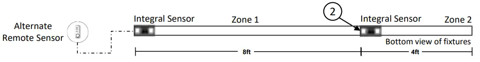
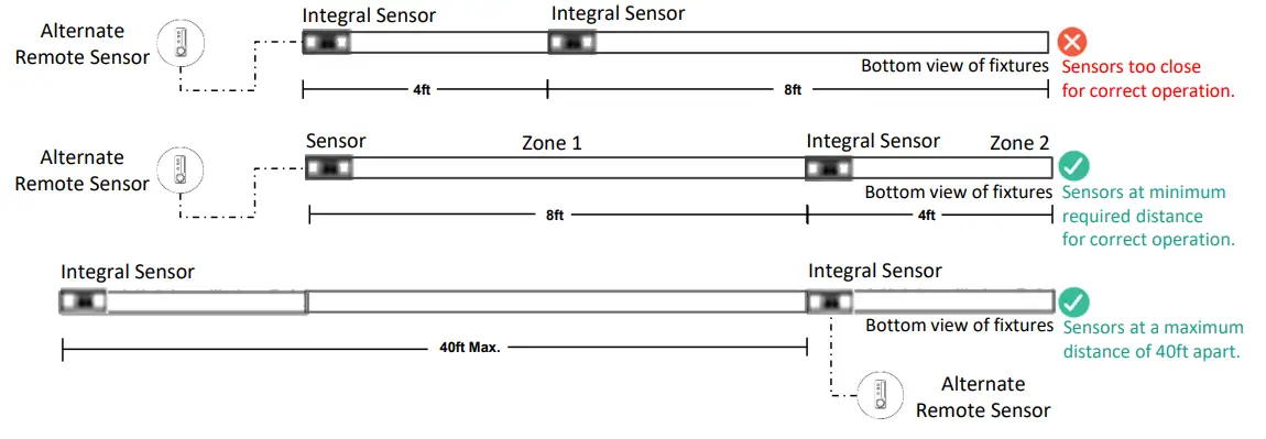
Sensor Spacing
- For correct operation, sensors should be placed a minimum distance of 8ft apart.
- Wireless sensors should be placed no further than 40ft apart for good wireless signal connection.
Important Consideration When Using Sensors in a Row
- For fixtures with wireless sensors (CS, SB or RA options):
DO NOT connect fixture purple & brown (or purple & grey/pink) control wires to an external dimming switch.
Fixture mains wiring should not be connected to a circuit with an external on/off switch. - For best aesthetic condition, place sensors at ends of row only so as not to break the continuous lens.
- For better occupancy coverage in longer rows, sensors may be placed mid run, but keep in mind this will break the continuous lens into discrete sections. Alternatively, remote sensor may be used, note the same wiring rules will apply.
![]() ATTENTION: Install in accordance with national and local building and electrical codes.
ATTENTION: Install in accordance with national and local building and electrical codes.
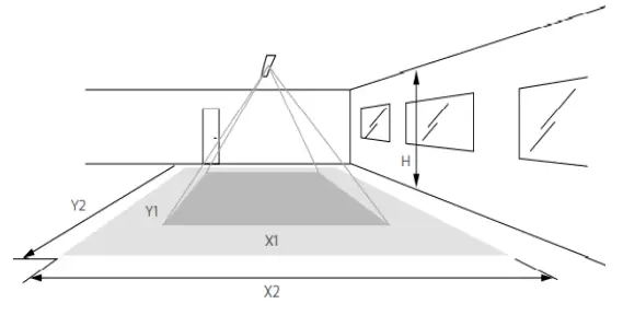
Occupancy Sensor Coverage:
Note: Longer dimension of detection area (Y1, Y2) is parallel to longer dimension of the luminaire.
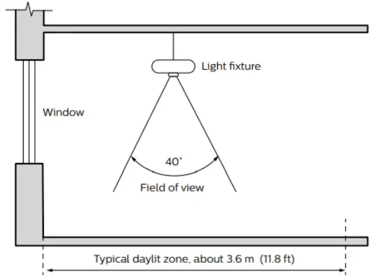
Daylight sensor
The light sensor measures the total amount of light in a circular field of approximately 80% of the PIR detection area. The following aspects should be observed during installation:
- Minimum distance from the window ≥2ft (0.6m).
- Prevent light reflections from outside entering the sensor (for example sunlight reflection on a car hood) as this will lead to incorrect light regulation.
As a guideline the formula 0.72 x H can be used to calculate the minimum distance between the window and sensor whereby H is the height from the bottom of the window to the sensor.
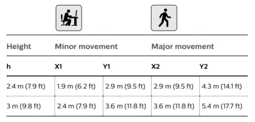
The detection area for the movement sensor can be roughly divided into two parts:
- Minor movement (person moving ≤3ft/s or 0.9m/s).
- Major movement (person moving ≥3ft/s or 0.9m/s).
Photosensor spatial response
![]() ATTENTION: Install in accordance with local and national building and electric codes.
ATTENTION: Install in accordance with local and national building and electric codes.
![]()
2021 Signify Holding. All rights reserved. The information provided herein is subject to change, without notice. Signify does not give any representation or warranty as to the accuracy or completeness of the information included herein and shall not be liable for any action in reliance thereon. The information presented in this document is not intended as any commercial offer and does not form part of any quotation or contract, unless otherwise agreed by Signify.
Signify North America Corporation
400 Crossing Blvd, Suite 600
Bridgewater, NJ 08807
Telephone: 855-486-2216
Signify Canada Ltd.
281 Hillmount Road,
Markham, ON, Canada L6C 2S3
Telephone: 800-668-9008
All trademarks are owned by Signify Holding or their respective owners.


