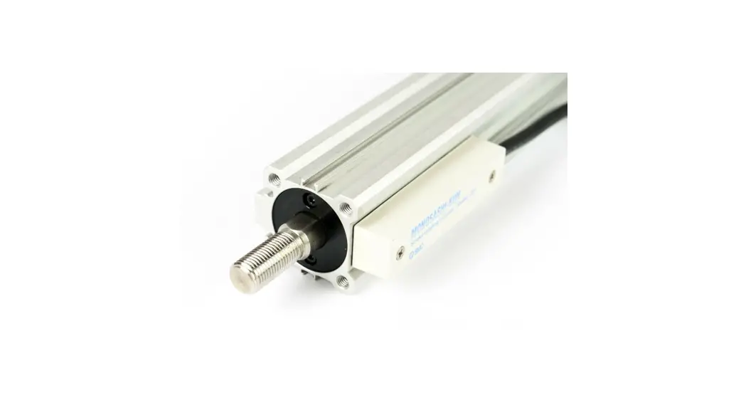
![]() ML2B Series Hyrodless Monosashi Kun Stroke Reading Cylinder
ML2B Series Hyrodless Monosashi Kun Stroke Reading Cylinder
Instruction Manual
PRODUCT NAME: HYRODLESS MONOSASHI-KUN
MODEL: ML2B Series
- READ THIS OPERATION MANUAL CAREFULLY BEFORE USE IT.
Specifications are subject to change without prior notice
Chapter 1: Read before Use
These safety instructions are intended to prevent a hazardous situation and/or equipment damage. These instructions indicate the level of potential hazard by label of “Caution”, ”Warning”, or ”Danger”. To ensure safety, follow the instructions below as well as ISO/IEC, JIS *1) and other safety laws *2).
| Operator error could result in injury or equipment damage. | |
| Operator error could result in serious injury or loss of life. | |
| In extreme conditions, there is a possible result of serious injury or loss of life. |
*1) ISO 4414: Pneumatic fluid power – General rules relating to systems
ISO 10218-1: 2006: Robots for industrial environments – Safety requirements – Part 1: Robot
IEC 60204-1: Safety of machinery – Electrical equipment of machines – Part 1:General requirements
JIS B 8370: General Rules for Pneumatic systems
JIS B 9960-1: Safety of machinery – Electrical equipment of machines – Part 1: General requirements
JIS B 8433-1: 2007: Robots for industrial environments – Safety requirements – Part 1: Robot
*2) Labor Safety and Sanitation Law etc.
![]() Warning
Warning
- The compatibility of pneumatic equipment is the responsibility of the person who designs the pneumatic system or decides its specifications.
Since the products specified here are used in various operating conditions, their compatibility for the specific pneumatic system must be based on specifications or after analysis and/or tests to meet your specific requirements. Ensuring the initial performance and safety are the responsibility of the person who decides the compatibility of the pneumatic system. Pneumatic systems should be constructed after full review of the details of the products other than specifications and possibilities of failures by checking the latest product information. - Only trained personnel should operate pneumatically operated machinery and equipment. Assembly, handling, or repair of pneumatic systems should be performed by trained and experienced operators.
- Do not service machinery/equipment or attempt to remove component until safety is confirmed.
a. Inspection and maintenance of machinery/equipment should only be performed after confirmation of safe locked-out control positions.
b. When equipment is to be removed, confirm the safety process as mentioned above. Cut the supply pressure for this equipment and exhaust all residual compressed air in the system.
c. Before machinery/equipment is re-started, take measure to prevent shooting-out of cylinder piston rod etc. - Contact SMC and take necessary safety measures if the products are to be used in any of the following conditions:
a. Conditions and environments beyond the given specifications, or if products are used outdoors.
b. Installation on equipment in conjunction with atomic energy, railway, air navigation, vehicles, medical equipment, food and beverages, recreation equipment, emergency stop circuits, press applications, or safety equipment.
c. An application which has the possibility of having negative effects on people, property, or animals, requiring special safety analysis.
d. When used in an interlock circuit, dual interlock such as mechanical protection is necessary in case of accident. Periodical inspection is also necessary to confirm proper operation.
Operating and Storage Environments![]() Warning
Warning
- Environments to avoid
Avoid using or storing the products in the following environments which may cause failures.
If the products need to be used or stored in those environments, take necessary measures.
a. Place where ambient temperature exceeds the range of 5℃ to 60℃.
b. Place where ambient humidity exceeds the range of 35% to 85% RH.
c. Place where condensation occurs due to sudden temperature change.
d. Place where atmosphere containing corrosive gas, flammable gas or organic solvent.
e. Place where atmosphere containing conductive powder such as dust and iron chips, oil mist, salt, or organic solvent, or splashing cutting chips, dust and cutting oil (water , liquid) over the products.
f. Place where the products are exposed to direct sunlight or radiated heat.
g. Place where strong electromagnetic noise is generated (place where strong electric field, strong magnetic field or surge is generated).
h. Place where static electricity is discharged or condition that the products have electrostatic discharge.
i. Place where strong high frequency is gene-rated.
j. Place where damages of thunder are expected.
k. Place where vibration or impact is directly given to the products.
l. Condition that the products are deformed by force or weight applied. - Do not close any objects which are affected by magnets.
Since magnets are built in cylinders, do not close magnetic disks, magnetic cards or magnetic tapes. The data may be destroyed.
Precaution on Design![]() Warning
Warning
- There is a possibility of dangerous sudden action by cylinders if sliding parts of machinery are twisted due to external forces, etc.
In such cases, human injury may occur; e. g., by catching hands or feet in the machinery, or damage to the machinery itself may occur. - Provide a cover to minimize the risk of human injury.
When a driven object or moving parts of a cylinder may cause the risk of human injury, design a structure to avoid contact with human body. - Securely tighten all stationary parts and connected parts of cylinders so that they will not become loose.
Tighten cylinders securely especially when they are used in high frequency or in locations where direct vibration or impact shock, etc. will be applied to the body of the cylinder. - Deceleration circuits or shock absorbers are needed in some cases.
If a driven object travels at a high speed or is heavy, impact will not be sufficiently absorbed only with the cylinder cushion. In such cases, use a circuit to decelerate the cylinder speed before the cushion becomes effective or use external shock absorbers to reduce impact. At this time, take the rigidity of machinery into account. - Consider possible drop of pressure in circuit due to power outage.
For cylinders used in clamping mechanism, a work may become loose due to less clamping force by pressure drop in circuit at the time of power outage. Install safety devices to prevent human injury and machinery damage. Measures should be taken to prevent drop of hanging or lifting equipment. - Consider possible loss of power sources.
Measures should be taken to protect against human injury and machinery damage in the event that there is a loss of air pressure, electricity or hydraulic power. - Design circuit to prevent shooting out of a driven object.
A driven object is quickly shot out when pressure is supplied from one side of the piston after air in the cylinder is exhausted in such cases that cylinder is actuated by exhaust center type of directional control valve or started after residual air is exhausted from the circuit. At this time, human injury may occur; e.g., by catching hands or feet in the machinery, or damage to the machinery itself may occur. Therefore, the machine should be designed and constructed to prevent shooting out. - Consider emergency stops.
Design the machinery so that human injury and/or damage to machinery and equipment will not be caused when machinery is stopped by a safety device under abnormal conditions, a power outage or a manual emergency stop. - Consider actions when operation is restarted after an emergency stop or abnormal stop.
Design the machinery so that human injury or equipment damage will not occur upon restart of operation. When the cylinder is required to return to the initial position, provide the equipment with a safe override. - Construct the machinery so that moving objects and the moving parts of the cylinder with brake do not come into direct contact with the human body.
- Use a balanced circuit in which lurching of the cylinder is prevented. When operation is locked in specified intermediate positions of the stroke, and air pressure is applied to only one side of the cylinder, the piston will lurch when the lock is released. This might cause injury or damage to machinery.
Selection![]() Warning
Warning
- Confirm the specifications.
The product in this manual is designed to be used only in industrial compressed air system. The product should not be used with pressures or temperatures outside the range of the specifications, as this may cause damage or malfunction, etc. - Intermediate stop
When cylinder piston is stopped intermediately by 3-position closed center type of directional control valve, intermediate stop positions may not be as precise and exact as hydraulic operation due to comprehensibility of air. Valves and cylinders are not guaranteed for zero air leakage, and stop position may not be held in a long period of time. Consult SMC for long term holding of stop positions. - When a cylinder is in a no-load and locked state, the holding force (maximum static load) is the lock’s ability to hold a static load that does not involve vibrations or shocks. To ensure braking force, the maximum load must be set as described below.
① For constant static loads, such as for drop prevention:
35% or less of holding force (Maximum static load)
Note) For applications such as drop prevention, consider situations in which the air source is shut off, and make selections based on the holding force of the spring locked state. Do not use the pneumatic lock for drop prevention purposes.
② When kinetic energy acts upon the cylinder, such as when effecting an intermediate stop, there are constraints in terms of the allowable kinetic energy that can be applied to the cylinder in a locked state. Refer to the allowable kinetic energy of the respective series. Furthermore, during locking, the mechanism must sustain the thrust of the cylinder itself, in addition to absorbing the kinetic energy. Therefore, even within a given allowable kinetic energy level, there is an upper limit to the amount of the load that canbe sustained.
– Maximum load for horizontal mounting: 70% or less of the holding force (Maximum static load) for spring lock
– Maximum load for vertical mounting: 35% or less of the holding force (Maximum static load) for spring lock
③ In a locked state, do not apply impact, strong vibrations or rotational forces. Any impact, strong vibrations or rotational forces from external sources could damage or shorten the life of the lock unit.
④ Although the cylinder can be locked in both directions.
![]() Caution
Caution
- Mount speed controller and adjust cylinder operation speed gradually from low speed to a desired speed.
Air Supply![]() Warning
Warning
- Do not use the product out of the specified ranges for pressure and temperature to pre-vent equipment damage and malfunction.
① Operating pressure:
Actuating part: 0.1 – 1.0MPa
Braking part: 0.3 – 0.5MPa
② Fluid & ambient temperature: 5 to 60ºC - Use clean air.
Do not use the product with compressed air includes chemicals, synthetic materials(including organic solvents), salinity, corrosive gases, etc., as this may cause damage or malfunction.
![]() Caution
Caution
- Install air filter.
Install air filter before and in vicinity of valve. The filter should be able to collect particles of 5 microns or smaller. A large quantity of drain may cause malfunction of pneumatic components. - Install after cooler, air dryer, auto drain, etc.
Compressed air that includes excessive condensate may cause malfunction of valve and other pneumatic equipment. To prevent this, install after cooler, air dryer, auto drain, etc.
Pneumatic circuit![]() Warning
Warning
- Be certain to use a pneumatic circuit which will apply balanced pressure to both sides of the piston when in a locked stop. (Refer to Chapter 6 for recommended pneumatic circuit.)
In order to prevent the cylinder lurching after a locked stop, use a circuit which applies balanced pressure to both sides of the piston when restarting or when manually releasing the lock, thereby canceling the force generated by the load in the direction of piston movement. - Use a solenoid valve for unlocking which has a larger effective area, as a rule 50% or more of the effective area of the cylinder drive solenoid valve.
(Refer to Chapter 6 for recommended pneumatic components.)
The larger the effective area is, the shorter the locking time will be, and stopping accuracy will be improved. - Place the solenoid for unlocking close to the cylinder, and no farther than the cylinder drive solenoid valve.
The shorter the distance from the cylinder, the shorter the overrun amount will be, and stopping accuracy will be improved. - Allow at least 0.5 seconds from a locked stop (intermediate stop of the cylinder) until release of the lock.
When the locked stop time is too short, the piston rod may lurch at a speed greater than the control speed of the speed controller. - When restarting, control the switching signal for the unlocking solenoid valve so that it acts before or at the same time as the cylinder drive solenoid valve.
If the signal is delayed, the piston rod may lurch at a speed greater than the control speed of the speed controller.
Installation![]() Warning
Warning
- Connect the slider end and the load with the lock released.
- Ensure that the equipment operates properly before the use.
- Operation manual
Do not install the products unless the safety instruction have been read and understood. Keep this operation manual on file for future reference.
![]() Caution
Caution
- Maintenance space
When installing the products, allow space for maintenance. - Do not give strong impact and/or excessive moment when work is mounted.
External force other than allowable moment may cause rattle at guide part and/or increase in sliding resistance. - Be careful to avoid scratches or dents, etc. on the sliding sections of the slider.
Wiring![]() Warning
Warning
- Preparation for wiring
Shut off the power before wiring (including insertion and removal of connectors). Mount a protective cover on the terminal block after-wiring. - Check the power
Make sure the power has sufficient capacity and voltages are within the specified range before wiring. - Grounding
Ground terminal block F.G. (Frame Ground). Do not ground it with devices generating strong electromagnetic noise. - Check wiring
Incorrect wiring may cause damage or malfunction of the products. Make sure the wiring is correct before operation.
![]() Caution
Caution
- Separation of signal wires from power wire
Avoid common or parallel wiring of signal and power wires to prevent malfunction due to noise. - Wiring arrangement and fixation
Avoid bending cables sharply at connector part or electrical entry in wiring arrangement.
In-proper arrangement may cause disconnection which in turn causes malfunction. Fix cables close enough not to give excessive force to the connector.
Piping![]() Caution
Caution
- Before piping
Remove cutting chips, cutting oil, dust, etc. in piping by flushing or cleaning before piping. Care should be taken especially that any cutting chips, cutting oil, dust, etc. do not exist after a filter. - At piping
① Foreign matter should not enter. Entering of foreign matter will cause malfunction.
② Cutting chips and sealing materials at piping threads should not enter valves when piping and fittings are screwed in. Leave 1.5 to 2 threads when seal tape is used.
Lubrication![]() Caution
Caution
- Lubrication of cylinder
① This cylinder is pre-lubricated and can be used without lubrication.
② In case of lubrication, use a equivalent of the turbine oil type 1 ISO VG32. Once lubrication is performed, it should be continued since the initial lubricant flows out causing malfunction.
Adjustment![]() Caution
Caution
- The locks are manually disengaged when the cylinder is shipped from the factory. Be sure to change them to the locked state before using the cylinder.
- Adjust the cylinder’s air balance. In the state in which a load is attached to the cylinder, disengage the lock and adjust the air pressure on the rod side and the head side of the cylinder to obtain a load balance. By maintaining a proper air balance, the piston rod can be prevented from lurching when the lock is disengaged.
- Adjust the mounting position of detection devices such as auto-switches.
Sensor unit![]() Caution
Caution
- Do not remove the sensor unit.
The position and sensitivity of the sensor is adjusted properly before shipment.
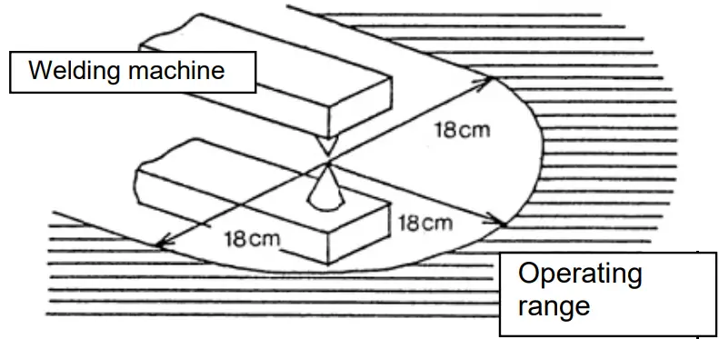
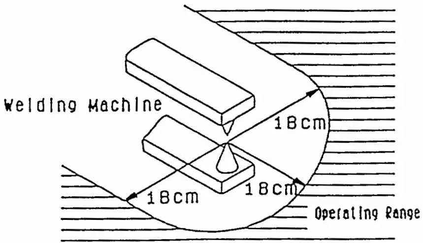
Removing or replacing the sensor may cause malfunction. - Operate the system with an external magnetic field of 14.5mT or less.
Strong magnetic field in the vicinity may cause malfunction, since ML2 sensor is magnetic type.
This is equivalent to a magnetic field of approximately 18 cm in radius from a welding area using a welding current of almost 15,000 amperes. To use the system in a magnetic field that exceeds this value, use a magnetic material to shield the sensor unit
- Do not pull sensor cable strongly.
Such action may cause failure. - Water shall be kept away from the sensor unit to avoid failure.
- Power supply line
Do not mount any switch or relay to power supply line (12 VDC).
Measurement![]() Caution
Caution
SMC products are not intended for use as instruments for legal metro logy.
Measurement instruments that SMC manufactures or sells have not been qualified by type approval tests relevant to the metro logy (measurement) laws of each country. Therefore, SMC products cannot be used for business or certification ordained by the metro logy (measurement) laws of each country.
Maintenance and Check![]() Warning
Warning
- Performing regular check
Check regularly that the products do not operate with failures unsolved. Check should be done by trained and experienced operators. - Dismantling of product and supply/exhaust of compressed air.
Before dismantling, ensure that drop preventing and runaway preventing treatments are properly provided, shut the power source of air supplied, and exhausts compressed air in the system. When starting operation again, operate the product with care after ensuring that a treatment for preventing extrusion is properly provided. - Prohibition of disassembly and modification
To prevent accidents such as failures and electric shocks, do not remove the cover to perform disassembly or modification. If the cover has to be removed, shut off the power before removal. - Disposal
Request a special agent for handling industrial waste to dispose the products.
Chapter 2: General Description/Features
2-1 General Description
Positioning with high reproducible has been realized by Hyrodless Mononucleosis, which brake and stroke sensor are installed in mechanical joint type godless cylinder (MY1B Series). (Stopping accuracy is ±0.5mm when specified controller. CEU2, is used.)
2-2 Features
Brake Structure
- Adoption of integrated pneumatic and spring
Slider stops instant due to quick response of brake. Also the current position is hold by spring lock when the air pressure is lowered or the compressed air is stopped. - Lock is possible for both directions
Lock is possible for reciprocation of cylinder stroke. - Easy maintenance
Brake can be replaced and disassembled, and can be opened manually for its unit structure. - Brake structure which does not give a load on cylinder
Slider can be stopped without losing its performance since brake does not give a load on cylinder for its structure, which spring acts on brake shoe directly to put between upper and lower brake plates.
Scale
- Minimum measuring unit : 0.1mm
This is measured by scale plate and detection head built-in body.
Chapter 3: System Configuration
3-1 System Configuration
HYRODLESS MONOSASHI-KUN (ML2 Series) can be used for measurement or to prevent falling besides positioning application.
| Model type | Function | Connected equipment | Application | |||||
| Brake | Scale | Keeping | Intermediate stop | Measurement | Positioning | |||
| ① | ML2B※ | CEU1 | ||||||
| ② | ML2B※ | CEU2 | ||||||
| ③ | ML2B※S | CEU1 | ||||||
| ④ | ML2B※B | Sequence, etc. | ||||||
3-2 Example of system Configuration
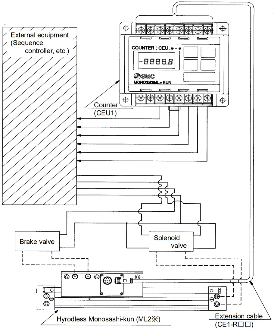
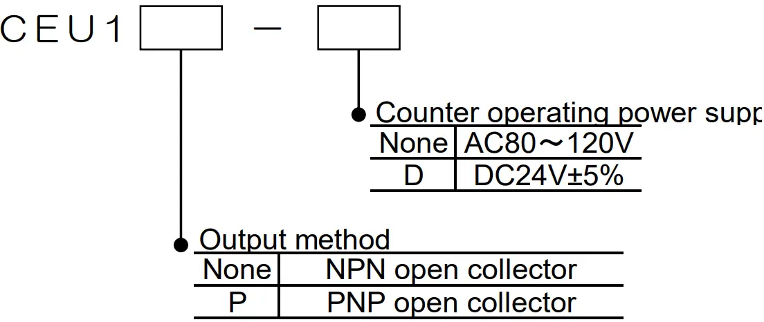
- For Keeping
Hyrodless Monosashi-kun + Counter
3 points preset counter : CEU1 Series
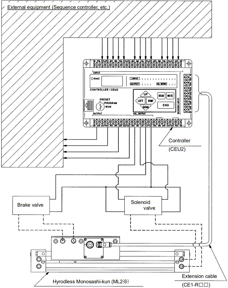
- For precise positioning (Stopping accuracy ±0.5mm)
Hyrodless Monosashi-kun + Controller
Controller : CEU2 Series
3-3 Pneumatic Circuit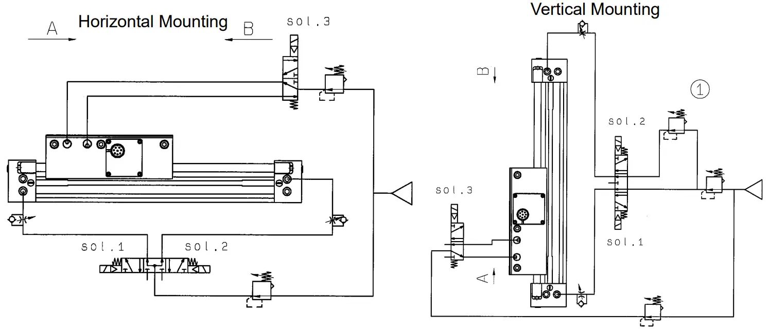 <Air Circuit Diagram>
| Sol.1 | Sol.2 | Sol.3 | |
| A | ON | OFF | ON |
| B | OFF | ON | ON |
| Stop | OFF | OFF | OFF |
Pneumatic Equipment
| Bore Size | Directional Valve | Brake Valve | Regulator | |
| Horizontal Mounting | Vertical Mounting | |||
| 25 | VFS25 | VFS24 | VFS21 | AR425 |
| 32 | VFS25 | VFS24 | VFS21 | AR425 |
| 40 | VFS25 | VFS24 | VFS21 | AR425 |
- Air Balance
・ With the above circuit, maintaining the slider at center by balancing both sides (left & right) supply pressure to achieve air balance state.
・ At the situation of vertical mounting, maintain the slider at the center and reduce the upper portion’s supply pressure accordingly to counter for the weight due to gravity. If air balance is not achieved, motion after center positioning will be either accelerating abnormally or false movement. Hence, the accuracy of positioning will be affected. - Tubing
・ Use larger diameter’s tube and reduce the tubing length between solenoid valve and cylinder, so as to increase position determination’s precision.
・ Connect brake valve near to slider. If tubing between brake valve and slider is long, its motion response time will be slower. Moreover, it may rush vigorously when brake is released.
・ During installation, connected tubing should be flushed thoroughly, and prevent dust and chips from entering into cylinder. - Supply Pressure
・ Set brake release port’s supply pressure as 0.3~0.5MPa. With supply pressure of below 0.3MPa, brake’s release will not be activated. While with pressure of above 0.5MPa, brake’s life span will be shortened.
・ Direct pressure supply from pressure line will cause pressure variation problem and thus, affect cylinder performance. Hence, it is advisable to connect regulator before driving and brake solenoid valve. Besides that, if there is a lot of cylinder activated and moving at the same time, use regulator with larger flow characteristic and install air tank.
・ Connect head cover tubing wisely with consideration of surrounding conditions.
The most suitable tubing can be selected according to the situation when tubing head cover.
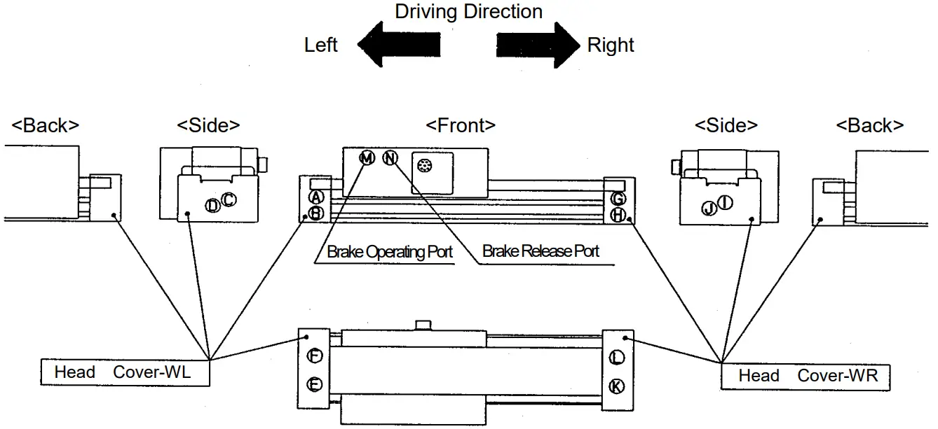
| Tube face No. | 1 | 2 | 3 | 4 | 5 | 6 | |
| Type of head cover | Head Cover-WL | Head Cover-WR | |||||
| Tubing face | Front | Side | Bottom | Front | Side | Bottom | |
| Operating direction | Left | A | C | E | G | I | K |
| Right | B | D | F | H | J | L | |
Note:
- Tubing should be group according to the grouping in the table above, 6 on each sides.
- SMC’s one-touch speed controller can be mounted directly on tubing No.1,2,4 and 5.
Installation dimension of bottom face
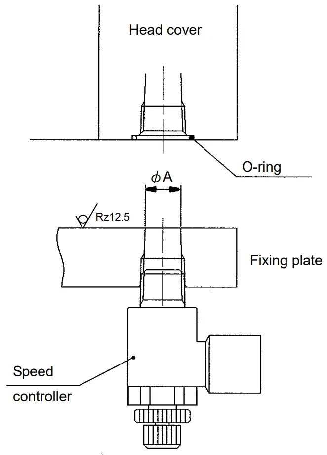
| φ25,φ32 | φ40 | |
| O-ring | C9 | C11.2 |
| φA | φ6 | φ8 |
Chapter 4: Operating Principle
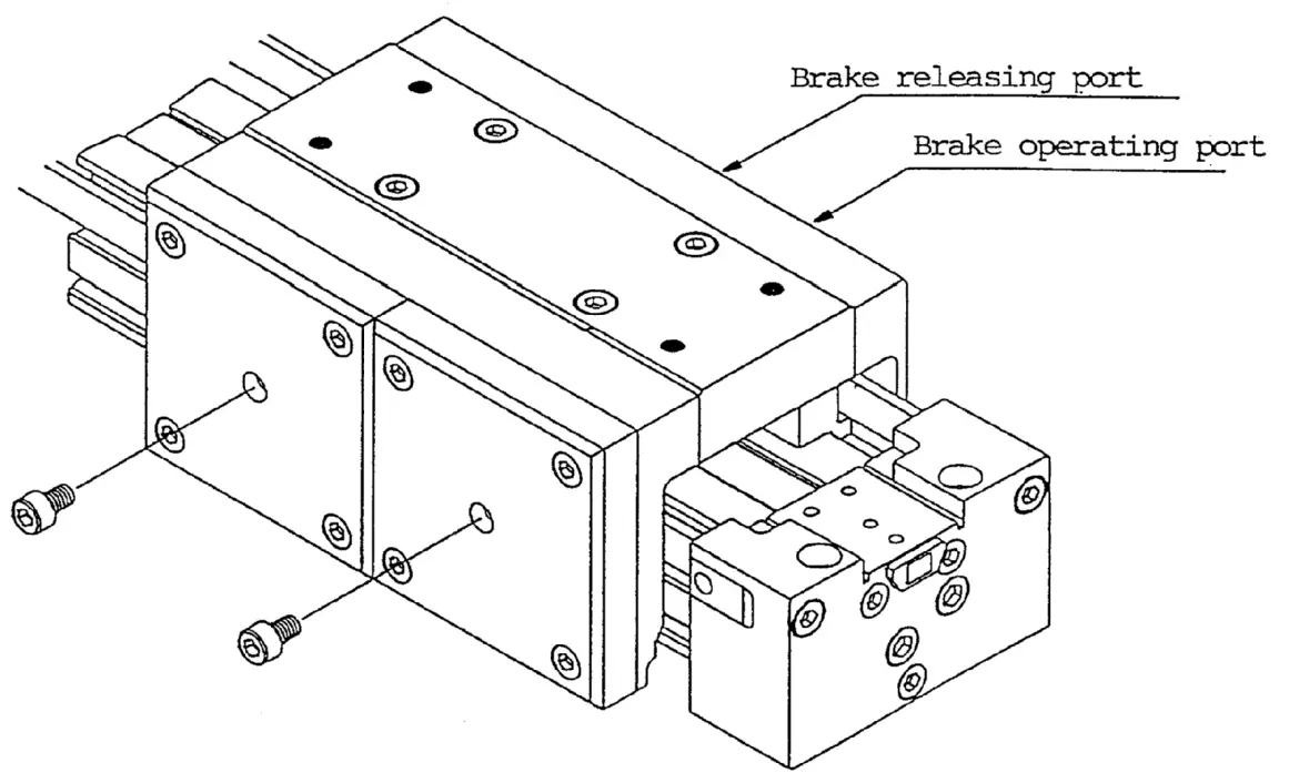
4-1 Operating principle of brake
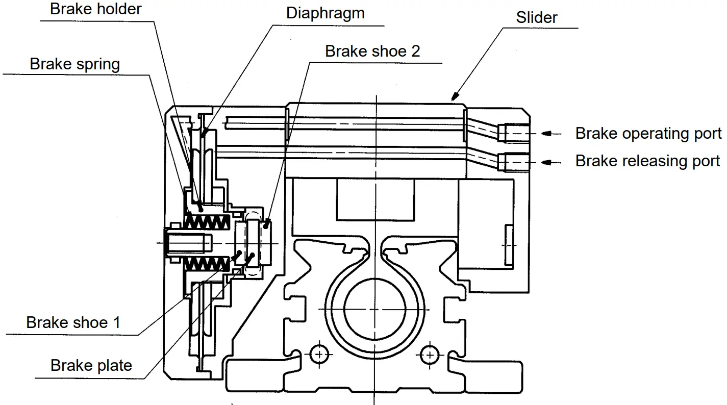
Brake operation
Spring force caused by brake spring and the air pressure supplied from brake operating port work on brake shoe 1 fixed with brake holder, bend brake plate fixed on head cover on both sides, and stop slider by putting brake plate between brake shoe 1 and brake shoe 2 fixed on the slider side.
Brake release
The air pressure supplied from brake releasing port work on diaphragm, decline brake spring, and cancel brake.
Chapter 5: Selecting Procedure
5-1 Precaution
Be sure to check with the procedure below before using Hyrodless Monosashi-kun. For positioning with CEU2, check with the procedure of “Operation Manual of Brake Positioning System (Rod less type)”.
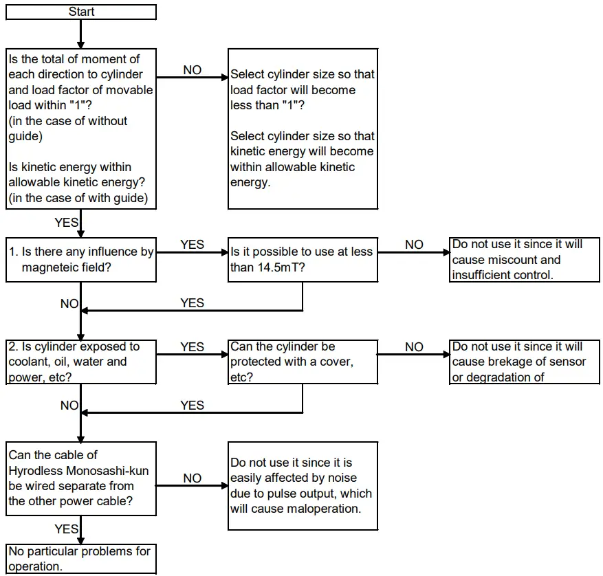
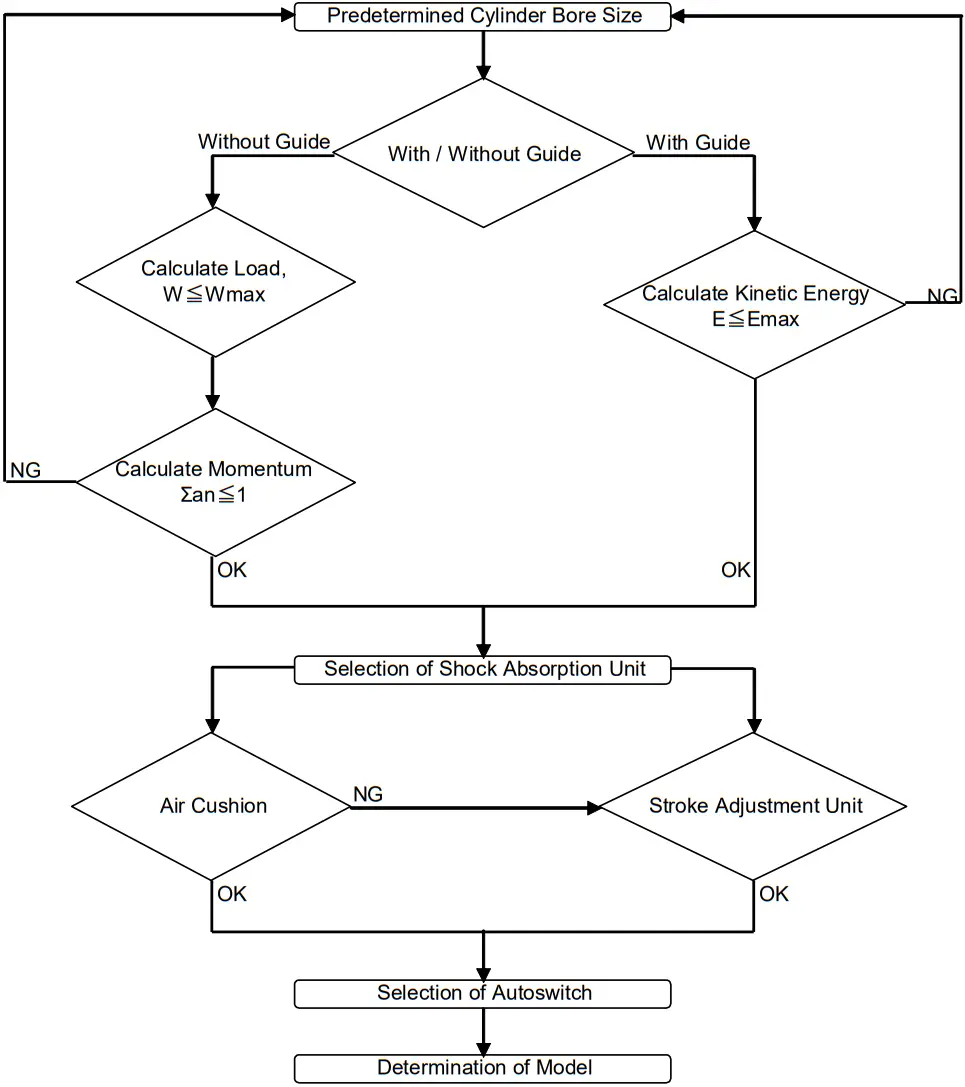
5-2 Selecting Procedure
Follow the procedure below to select the most suitable ML2 series.
As allowable moment, maximum movable load, and allowable kinetic energy vary with the conditions, such as mounting position, piston speed, and with / without guide,
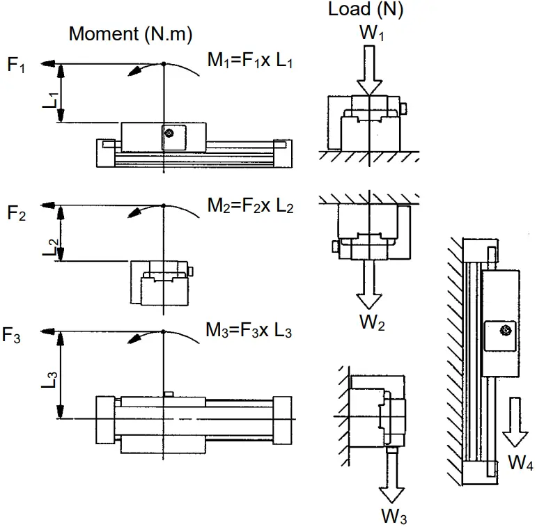
- maximum movable load,
- static moment,
- dynamic moment (during impact with stopper and locking), and
- allowable kinetic energy should be considered so that the total amount of load factor will not exceed 1 (∑an≦1) when calculating allowable load. (In the case of ∑an>1, select a cylinder with larger bore size.) When positioning is necessary, maximum speed should be not more than 500mm/s.
Operating Condition
W: Load (N)
Va: Average Speed (mm/s)
P: Operating Pressure (Mpa)
Mounting Direction:
Guide:
Impact Absorption:
Auto switch:
5-3 Selection Information
| W | (N) | : Load |
| We | (N) | : Impact loading (during locking or knocking of stopper) |
| V | (m/s) | : Impact speed (during locking or knocking of stopper) |
| Va | (m/s) | : Average speed |
| L | (m) | : Distance from C.G. of load |
| M | (Nm) | : Maximum moment |
| E | (J) | : Kinetic energy of load |
| g | (m/s) | : Gravity acceleration (9.8 m/s²) |
<Piston speed>
V=1.4xVa
<Maximum load>
We=1.4xVaxWx10
<Maximum allowable moment>![]()
<Load factor>![]()
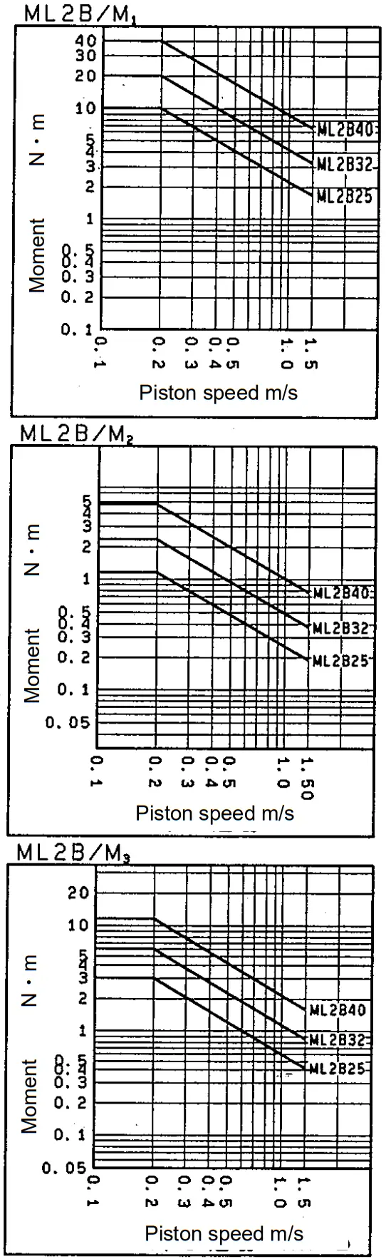
F ^: Calculated load
F Max: Maximum allowable load under the condition of allowable speed (value obtained from graph)
<Allowable kinetic energy>![]()
- Allowable moment and maximum load
Model Allowable moment N.m Maximum load N M1 M2 M3 W1 W2 W3 W4 ML2B25 10.0 1.2 3.0 200.0 58.0 65.0 100.0 ML2B32 20.0 2.4 6.0 300.0 80.0 96.0 150.0 ML2B40 40.0 4.8 12.0 500.0 106.0 140.0 250.0 - Allowable kinetic energy
ML2B25 ML2B32 ML2B40 Allowable kinetic energy J 0.43 0.68 1.21
Max. Allowable Momentum
Select cylinder accordingly with refer to the graph below. Its momentum should not over the specified range. However, selected cylinder may have larger loading value than specified max. load. Counter check with loading condition.
Allowable kinetic energy
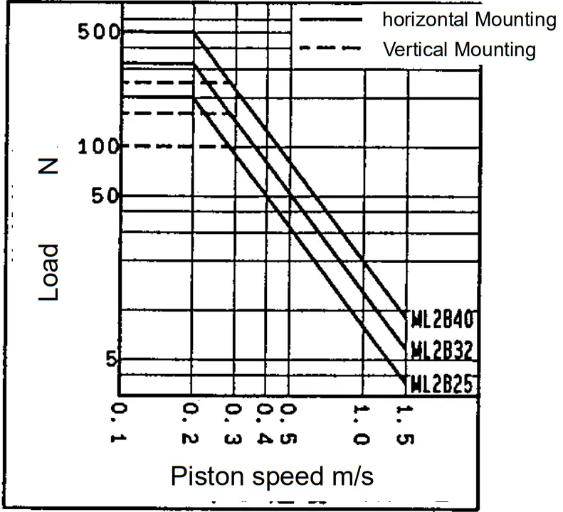
Max. Load
Select cylinder accordingly with refer to the graph below. Its load should not over than specified range. However, selected cylinder may have larger momentum value than specified max. momentum. Counter check with momentum condition.
5-4 Example of selection
Ⅰ. Without Guide
- Operating Conditions
Model ML2B32 Load 15N Speed, Va 0.25 m/s Pressure 0.5MPa L1 0.05m L2 0.05m 
Loading Static Load Dynamic Load ① Side load due to W W3 - ② Moment due to W M2 - ③ Moment due to we when stopping - M3 V ④ 〃 - M1 V - Static Load <normal load>
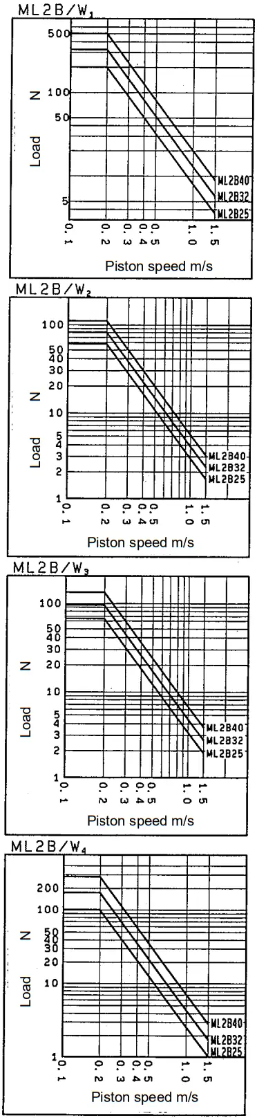
① W3 max=60 Nm (Checked from graph with Va)
② M2 max=2N・m (Checked from graph with Va)
M2=Wx L1=15 x 0.05=0.725 N・m
- Dynamic load <load applied during stopping)
Impact Loading, We=1.4 x 10 x Va x W=1.4 x 10 x 0.25 x 15=52.2 N
③ M3 max=3.5 N・m (Checked with V=1.4 x Va)
④ M1 max=12 N・m (Checked with V=1.4 x Va)
- Examination of load factor
an ① 0.25 ② 0.375 ③ 0.25 ④ 0.073 ∑an 0.948 Decision OK from ∑an≦1 
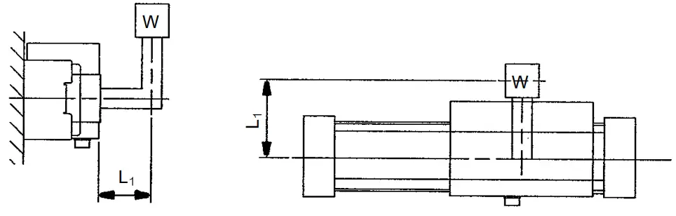
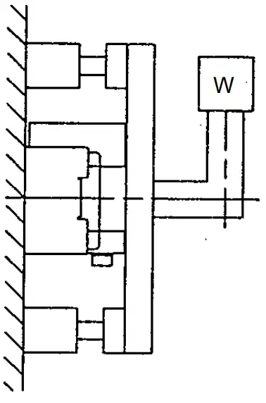
Ⅱ. With Guide
- Operating conditions

Model ML2B25 Load 30N Speed , Va 350mm/s Mounting position wall  The weight of table is considered as 0 in this case. However, during actual operation, the weight of table should be taken into consideration.
 - Allowable kinetic energy
E max=0.43 (J)
V=Va x 1.4=350 x 1.4=490 mm/s
- Examination of load factor
a5 = 0.84 ≦ 1 OK
With above allowable value, there is no problem on the selection.
![]() If values are in the range of graph in page 19, there is no problem on the operating conditions.
If values are in the range of graph in page 19, there is no problem on the operating conditions.
Chapter 6: Specifications
6-1 Cylinder Specifications
| Bore size | φ25 | φ32 | φ40 | |
| Fluid | Air | |||
| Operating method | Cylinder | Double acting type | ||
| Brake | Integrated pneumatic and spring | |||
| Operating pressure range | Cylinder | 0.1~0.8MPa | ||
| Brake | 0.3~0.5MPa | |||
| Proof pressure | Cylinder | 1.2MPa | ||
| Brake | 0.75 MPa | |||
| Piston speed | 100~1500mm/s (during positioning, 100~500mm/s) | |||
| Ambient and fluid temperature | 5~50℃(No freezing) | |||
| Cushion | Both sides air cushion | |||
| Brake type | Integrated pneumatic and spring | |||
| Lubrication | Not required | |||
| Stroke tolerance mm | 0~+1.8 | |||
| Hardware | JIS B 0209 | |||
| Port size | Front and side port | Rc1/8 | Rc1/4 | |
| Bottom port | φ5 | φ6 | φ8 | |
6-2 Sensor specifications
| Cable | (Standard product with connector: R04-R8M made by TAJIMI MUSEN DENKI CO.) |
| Max. transmission distance | 20m (when using 6 core twist spare shield wire) |
| Position detection method | Magnetic scale rod, Detection head (Incremental type) |
| Magnetic field resistance | 14.5mT |
| Power supply | DC12V±10% (Power supply ripple : Less than 1%) |
| Current consumption | 40mA |
| Resolution | 0.1mm / pulse |
| Accuracy | ±0.2mm (20℃) Note1) |
| Output method | Open collector (DC35V, 80mA) |
| Output signal | Phase A/B phase difference output |
| Max. response speed | 500mm/s |
| Withstand voltage | AC 500 V, For one minute (Between case and 12E) |
| Insulation resistance | DC500V, 50MΩ (Between case and 12E) |
| Shock resistance | 33.3 Hz 6.8 G X,Y directions : For 2 hours, Z : 4 hours In accordance with JIS D1061 |
| Impact resistance | 30G X,Y,Z directions : 3 times |
| Extension cable (Option) | 5m,10m,15m,20m (Connector : R03-P8F made by TAJIMI MUSEN DENKI CO.) |
Note 1) Include digital error of the counter (CEU1,CEU5).
The accuracy as a whole unit after assembling to the device may vary depending on the mount condition and environment. Please execute calibration of the device on customer’s own responsibility.
Chapter 7: How to Order
7-1 Cylinder (Hyrodless Monosashi-kun)
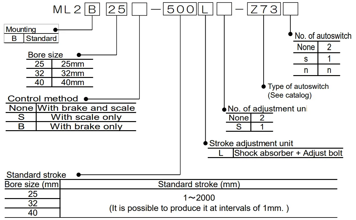
Option
Stroke adjustment unit
| φ25 | MY-A25L |
| φ32 | MY-A32L |
| φ40 | MY-A40L |
Stroke adjustment unit
| φ25 | MY-S25A | MY-S25B |
| φ32 | MY-S25A | MY-S25B |
| φ40 | MY-S32A | MY-S32B |
7-2 Controller
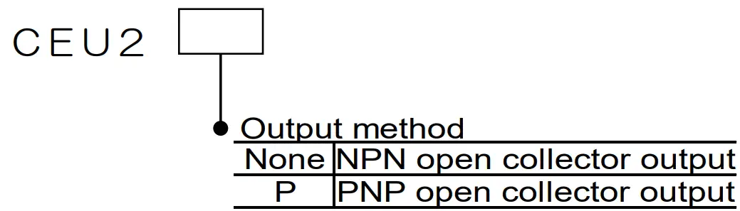
3 points preset counter
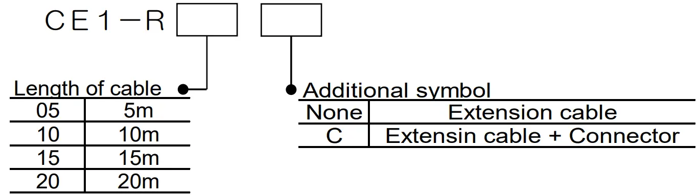
7-3 Extension cable
Connection of connector
| Contact | A | B | C, D | E | F | G |
| Color of wire | White | Yellow | Brown, Blue | Red | Black | (Shield) |
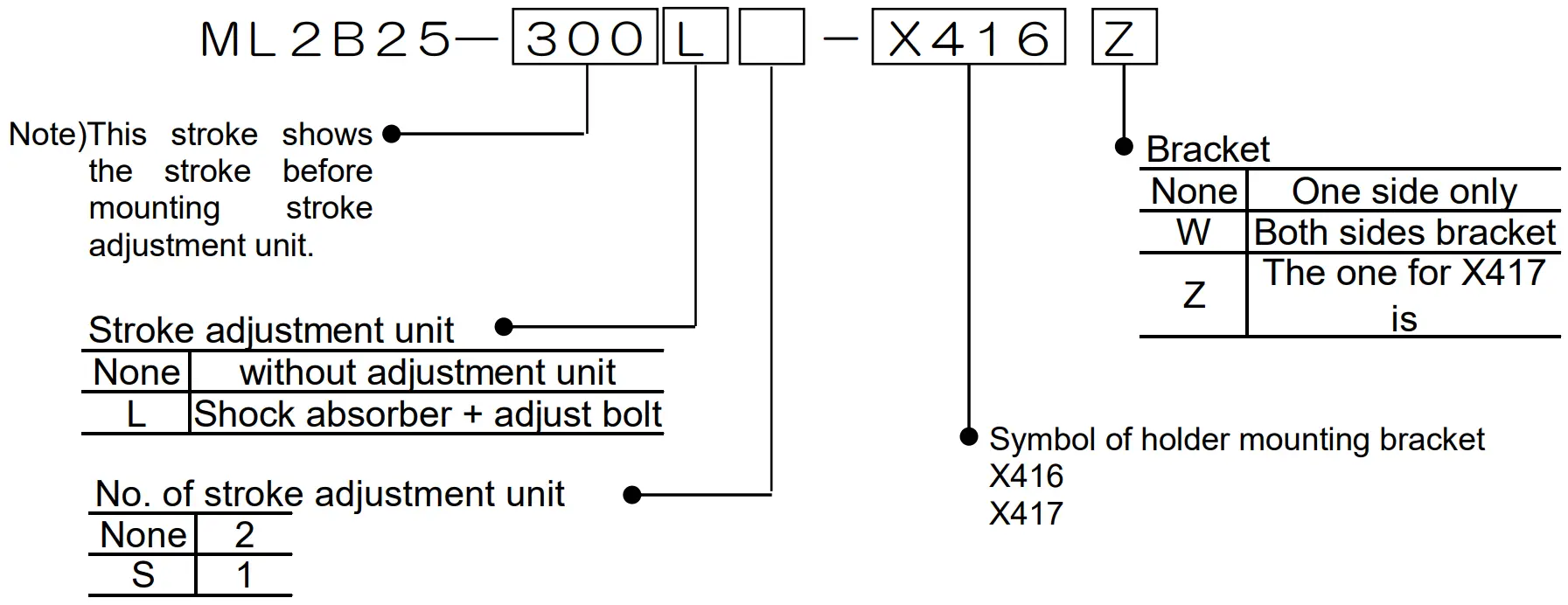
7-4 Specifications of Made to order ML2B
[Holder mounting bracket : ① ②]
Holder mounting bracket ① : -X416
Holder mounting bracket ② : -X417
Stroke fine adjustment range
| Holder mounting bracket | X416 | X417 | ||
| Length of spacer L (mm) | ML2B25 | 11.5 | 23 | |
| ML2B32 | 12 | 24 | ||
| ML2B40 | 16 | 32 | ||
| Stroke fine adjustment range (mm) | ML2B25 | per one side | -11.5~-23 | -23~-34.5 |
| Both sides | -23~-46 | -46~-69 | ||
| ML2B32 | per one side | -12~-24 | -24~-36 | |
| Both sides | -24~-48 | -48~-72 | ||
| ML2B40 | per one side | -16~-32 | -32~-48 | |
| Both sides | -32~-64 | -64~-96 | ||
How to order
- When ordering stroke adjustment unit integrated into cylinder body.

- When ordering stroke adjustment unit only.
Add “X416” and “X417” at the end of part No. of unit.
Ex. MY-A25L-X416 - When ordering holder mounting bracket only.
Add “N” at the end of part No. of unit.
Ex. MY-A25L-X416N
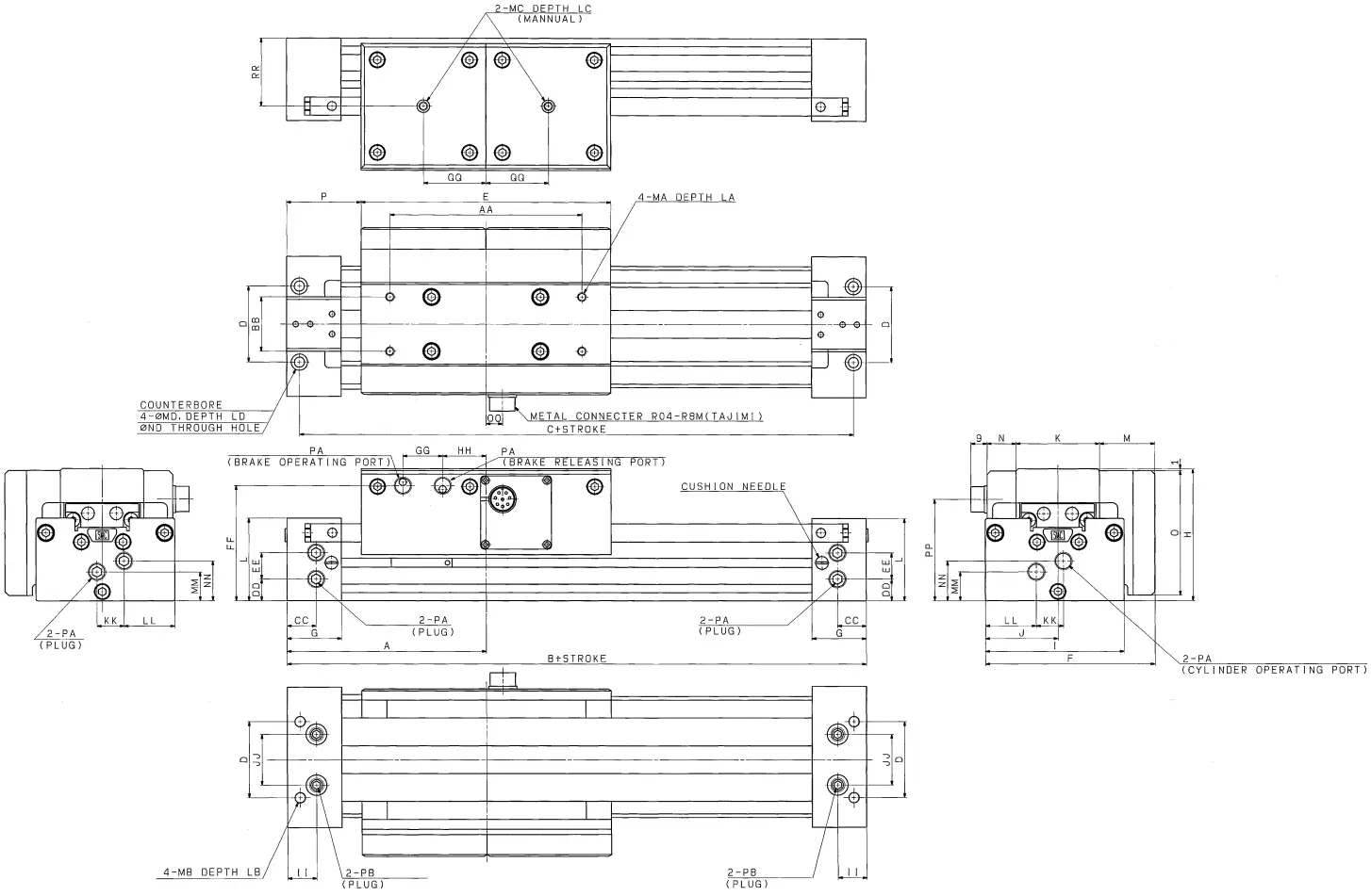
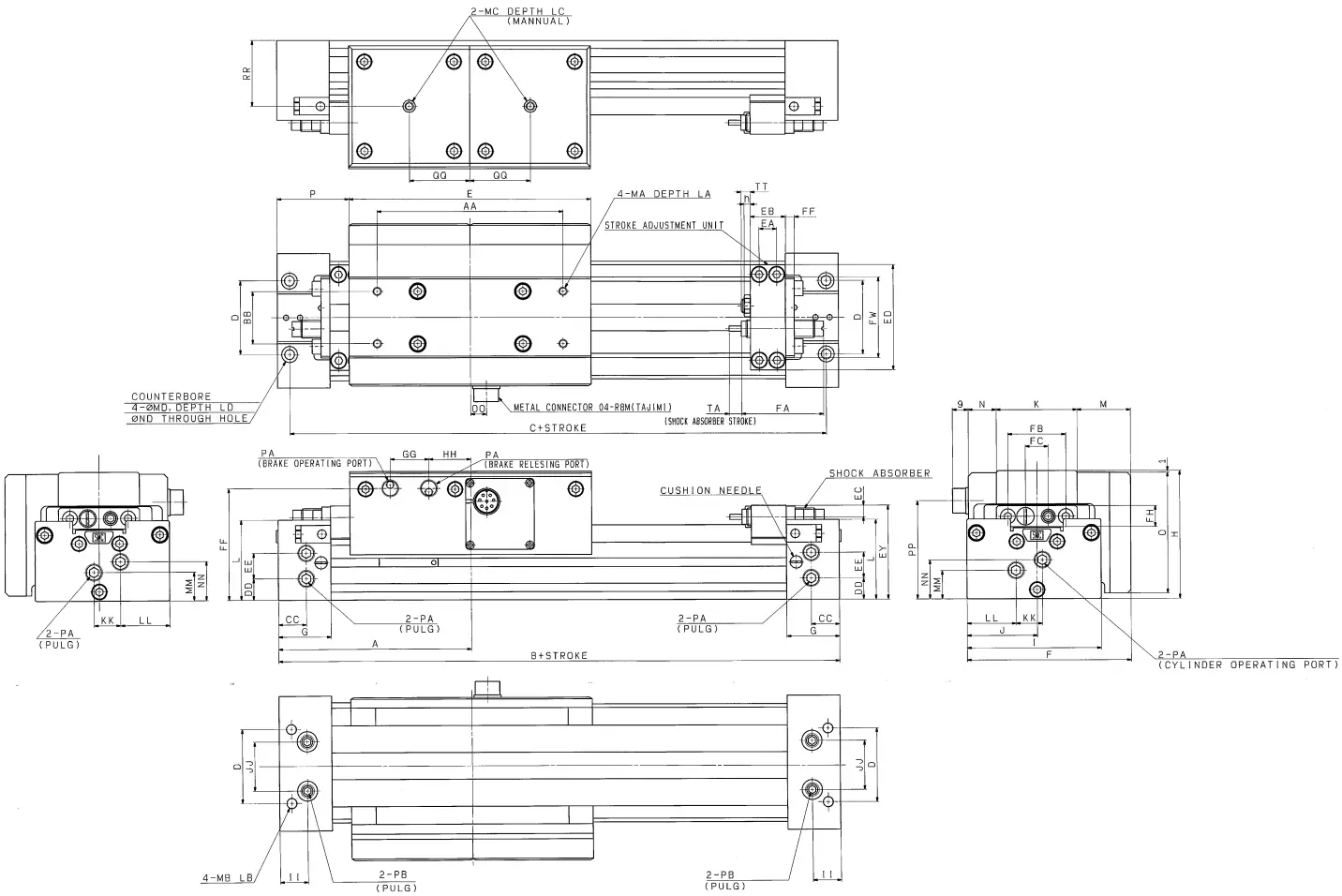
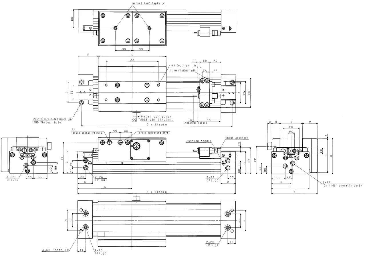
Chapter 8: External Dimension Drawing
8-1 Hyrodless Monosashi-kun (with brake, scale)
| A | B | C | D | E | F | G | H | I | J | K | L | M | N | O | P | |
| ML2B25 | 110 | 220 | 206 | 42 | 138 | 93.5 | 30 | 73 | 76.5 | 40 | 46 | 45.5 | 30.5 | 16 | 69 | 41 |
| ML2B32 | 140 | 280 | 264 | 51 | 168 | 107.5 | 37 | 88 | 91 | 46.5 | 58 | 54 | 32 | 15 | 84 | 56 |
| ML2B40 | 170 | 340 | 322 | 59 | 204 | 130.5 | 45 | 106 | 110 | 55 | 68 | 64 | 41.5 | 19 | 102 | 68 |
| AA | BB | CC | DD | EE | FF | GG | HH | IL | JJ | KK | LL | MM | NN | O | PP | Q | RR |
| 106 | 30 | 16 | 12 | 13.5 | 63.5 | 22 | 24 | 16 | 28 | 15 | 28 | 16 | 22 | 9 | 56 | 34.5 | 37.5 |
| 133 | 36 | 19 | 15 | 16 | 77.5 | 27 | 32 | 19 | 32 | 16 | 30.5 | 21.0 | 26 | 10 | 62.5 | 42 | 45 |
| 164 | 40 | 23 | 16.5 | 22 | 95 | 35 | 37 | 23 | 36 | 17.5 | 37.5 | 24.5 | 37.5 | 23 | 77 | 51 | 54 |
| MA | LA | MB | LB | MC | LC | MD | LD | ND | PA | PB |
| M5x0. 8 | 9 | M6x1 | 9.5 | M5x0. 8 | 9.5 | 9 | 5.5 | 5.5 | Rc(PT)1/13 | MPT)1/16, Rc(P1)1/16 |
| M6x1 | 12 | M8x1. 25 | 15 | M6x1 | 12 | 11 | 6.5 | 6.5 | Rc(PH1/8 | |
| M6x1 | 12 | M10x1. 5 | 15 | M8x1. 25 | 12 | 14 | 8.5 | 8.8 | Rc(PT)1/4 | Re(PT)1/8 |
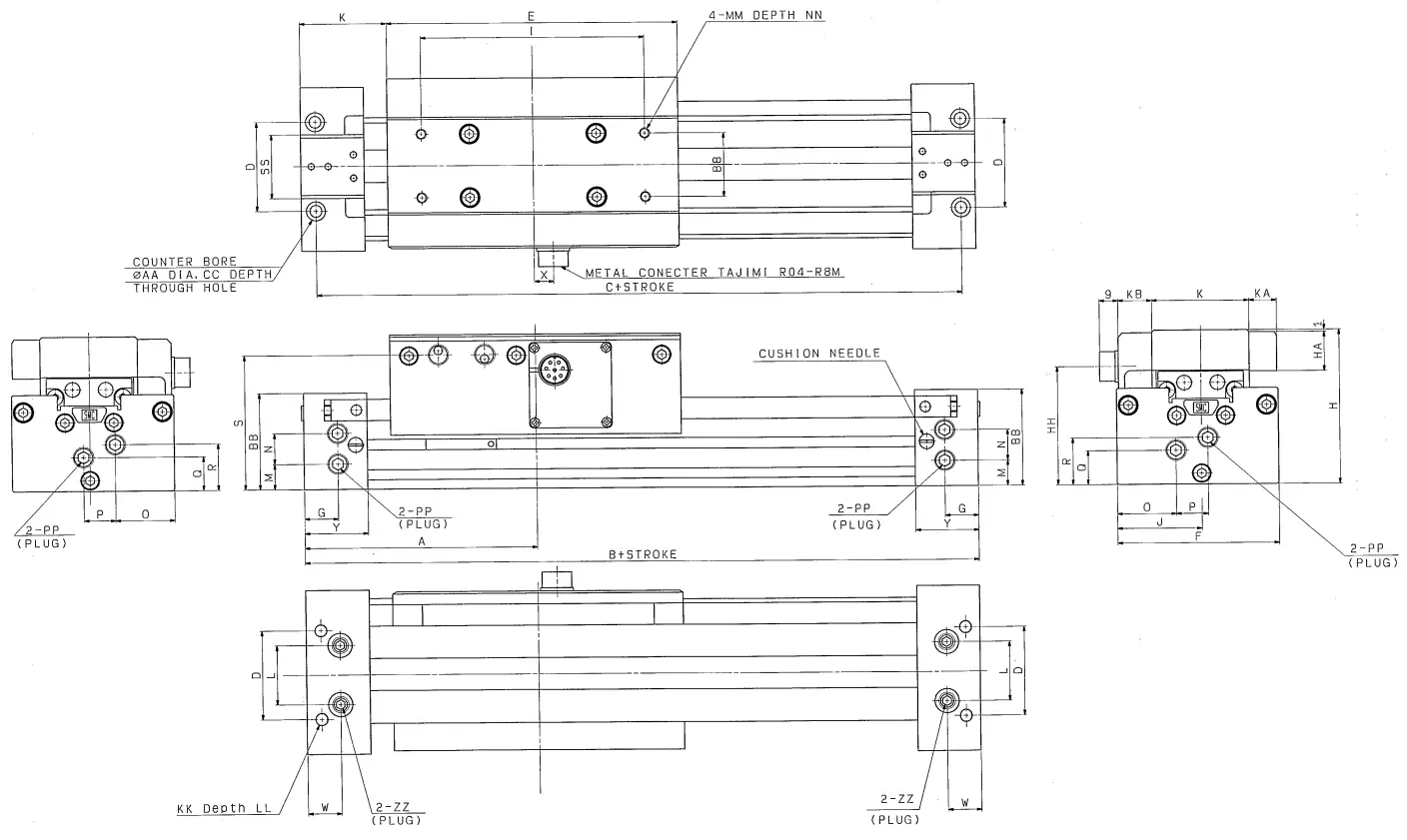
8-2 With scale
| A | B | C | D | E | F | G | H | I | J | K | L | M | N | O | P | |
| ML2B25 | 110 | 220 | 206 | 42 | 138 | 915 | 16 | 73 | 76.5 | 40 | 46 | 28 | 12 | 14.5 | 28 | 15 |
| ML2B32 | 140 | 280 | 264 | 51 | 168 | 107.5 | 19 | 88 | 91 | 46.5 | 58 | 32 | 15 | 16 | 30.5 | 16 |
| ML2B40 | 170 | 340 | 322 | 59 | 204 | 130.5 | 23 | 106 | 110 | 55 | 68 | 36 | 16.5 | 22 | 31.5 | 23.5 |
| G | R | S | T | U | W | X | Y | Z | AA | BA | CC | DD | EE | HA | HH | KA | KB |
| 16 | 22 | 63.5 | 23.5 | 22 | 16 | 9 | 30 | 31.5 | 9 | 45.5 | 5.5 | M5x0.8 | 9.5 | 13.5 | 55 | 13 | 16 |
| 22. | 26 | 77.5 | 32.5 | 27 | 19 | 10 | 37 | 42 | 12 | 54 | 6.5 | M6x1 | 12 | 19.5 | 62.5 | 15 | 15 |
| 25. | 37.5 | 95 | 50.5 | 35 | 23 | 23 | 45 | 50.5 | 12 | 64 | 8.5 | 148×1.25 | 12 | 21.5 | 77 | 19 | 19 |
| KK | LD | LL | MM | NN | PP | SS | YY | ZZ |
| M6x1 | 5.5 | 9.5 | M5x0. 8 | 9 | Rc(PT)1/8 | 30 | 37.5 | WT /16 |
| 48×1.25 | 6.5 | 16 | M6x1 | 12 | IMPT)1/8 | 36 | 45 | Rc(P1)1/16 |
| M10x1.5 | 8.5 | 15 | M6x1 | 12 | Rc(PT)1/4 | 40 | 54 | Pc(PT)1/8 |
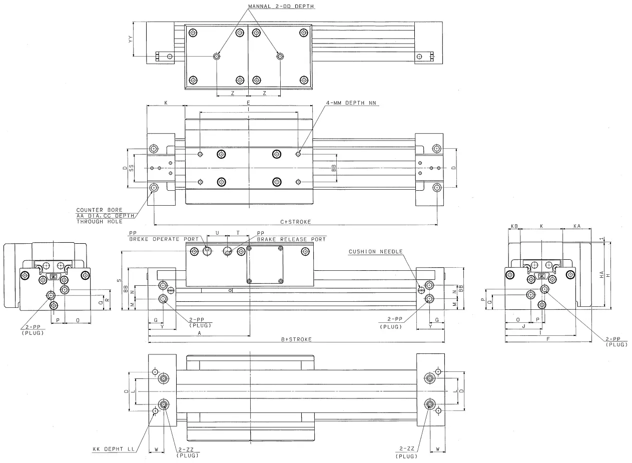
8-3 With brake
| A | B | C | D | E | F | G | H | I | J | K | L | M | N | O | P | |
| ML2B25 | 110 | 220 | 206 | 42 | 138 | 93.5 | 16 | 73 | 76.5 | 40 | 46 | 28 | 12 | 14.5 | 28 | 15 |
| ML2B32 | 140 | 280 | 264 | 51 | 168 | 107.5 | 19 | 88 | 91 | 46.5 | 58 | 32 | 15 | 16 | 30.5 | 16 |
| ML2B40 | 170 | 340 | 322 | 59 | 204 | 130.5 | 23 | 106 | 110 | 55 | 68 | 36 | 16.5 | 22 | 31.5 | 23.5 |
| Q | R | S | T | U | w | Y | Z | AA | BB | CC | DD | EE | HA | KA | KB | KK | LD |
| 16 | 22 | 64. | 23.5 | 22 | 16 | 30 | 34.5 | 9 | 45.5 | 5.5 | M5x.8 | 10. | 69 | 30.5 | 16 | M6x1 | 5.5 |
| 22. | 26 | 77.5 | 32.5 | 27 | 19 | 37 | 42 | 12 | 54 | 6.5 | M6x1 | 12 | 84 | 32 | 15 | M8x1.25 | 6.5 |
| 25. | 37.5 | 95 | 50.5 | 35 | 23 | 45 | 51 | 12 | 64 | 8.5 | M8x1.25 | 12 | 102 | 41.5 | 19 | 4105. | 8.5 |
| LL | MM | NN | PP | SS | YY | ZZ |
| 9.5 | M5x0.8 | 9 | Rc(PT)1/8 | 30 | 37.5 | Rc(PT)1/16 |
| 16 | M6x1 | 12 | Rc(PT)1/8 | 36 | 45 | Rc(PT) 1/16 |
| 15 | M6x1 | 12 | Rc(PT)1/4 | 40 | 54 | Rc(PT)1/8 |
8-4 With shock absorber
| A | B | C | D | E | F | G | H | I | J | K | L | M | N | O | P | |
| ML2825 | 110 | 220 | 206 | 42 | 138 | 915 | 30 | 73 | 77. | 40 | 46 | 45.5 | 30.5 | 16 | 69 | 43 |
| ML2B32 | 140 | 280 | 264 | 51 | 168 | 107.5 | 37 | 88 | 91 | 46.5 | 58 | 54 | 32 | 16 | 84 | 56 |
| _ML2340 | 170 | 340 | 322 | 59 | 204 | 130.5 | 45 | 106 | 110 | 55 | 68 | 64 | 41.5 | 19 | 102 | 68 |
| AA | BB | CC | DD | EE | FF | GG | HH | II | JJ | KK | LL | MM | NN | OO | PP | RR | |
| 106 | 30 | 16 | 12 | 13.5 | 63.5 | 22 | 24 | 16 | 28 | 15 | 28 | 16 | 22 | 9 | 56 | 34.5 | 38. |
| 133 | 36 | 19 | 15 | 16 | 77.5 | 27 | 32 | 19 | 32 | 16 | 30.5 | 21.5 | 26 | 10 | 62.5 | 42 | 45 |
| 164 | 40 | 23 | 16.5 | 22 | 95 | 35 | 37 | 23 | 36 | 17.5 | 37.5 | 24.5 | 37.5 | 23 | 77 | 51 | 54 |
| MA | LA | MB | LB | MC | LC | MD | LO | ND | PA | PB |
| M5x0. 8 | 9 | M6x1 | 9.5 | M5x0. 8 | 10. | 9 | 5.5 | 5.5 | Rc(P111/8 | RcP111/16 |
| M6x1 | 12 | M8x1. 25 | 15 | M6x1 | 12 | 11 | 6.5 | 6.5 | Rc(PT)1/8 | ROT)1/16 |
| M6x1 | 12 | MlOxl. 5 | 15 | Maxi. 25 | 12 | 14 | 8.5 | 8.5 | Rc(P1)1/4 | Rc(P1)1/8 |
| h | EA | EB | EC | ED | EY | FA | FB | FC | FF | FH | FW | TA | TT |
| 4. | 10 | 20 | 6.5 | 60 | 53.5 | 46.7 | 33 | 13 | 6 | 12 | 46 | 7 | MAX.16.5 |
| 5. | 12 | 25 | 8.5 | 74 | 67 | 67.3 | 43 | 17 | 6 | 16 | 56 | 12 | MAX. 20 |
| 5. | 15 | 31 | 9.5 | 94 | 81.5 | 67.3 | 43 | 17 | 6 | 16 | 56 | 12 | MAX. 25 |
8-5 With stroke adjustment unit, X416
| A | B | C | D | E | E | F | G | I | J | K | L | M | N | O | P | |
| ML2B25 | 110 | 220 | 206 | 42 | 138 | 93.5 | 30 | 73 | 76.5 | 40 | 46 | 45.5 | 30.5 | 16 | 69 | 43 |
| ML2B32 | 140 | 280 | 264 | 51 | 168 | 107.5 | 37 | 88 | 91 | 46.5 | 58 | 54 | 32 | 16 | 84 | 56 |
| ML2840 | 170 | 340_322 | 59 | 204 | 130.5 | 45 | 106 | 110 | 55 | 68 | 64 | 41.5 | 19 | 102 | 68 | |
| AA | BB | CC | DD | EE | FF | GG | HH | II | JJ | KK | LL | MM | NN | OO | PP | RR | |
| 106 | 30 | 16 | 12 | 13.5 | 63,5 | 22 | 24 | 16 | 28 | 15 | 28 | 16 | 22 | 9 | 56 | 34.5 | 37,5 |
| 133 | 36 | 19 | 15 | 16 | 77,5 | 27 | 32 | 19 | 32 | 16 | 30.5 | 21,5 | 26 | 10 | 62,5 | 42 | 45 |
| 164 | 40 | 23 | 16.5 | 22 | 95 | 35 | 37 | 23 | 36 | 18. | 37.5 | 24.5_37.5_ 23 | 77 | 51 | 54 | ||
| MA | LA | Ma | LB | MC | LC | MD | LD | ND | PA | PB |
| M5x0.8 | 9 | M6 x 1 | 9.5 | M5 x 0.8 | 9.5 | 9 | 5.5 | 5,6 | Rel/8 | Rc1/16 |
| M6x1 | 12 | M 8 x 1.25 | 15 | M6 x 1 | 12 | 11 | 8.5 | 6,8 | Rcl/8 | Rel./16 |
| M8x1.25_ 14 | M10x1,5 | 15 | M8 x 1.25 | 12 | 14 | 8,5 | 8,6 | Rc1/4 | Rcl/8 | |
| h | EA | EB | EC | ED | EY | FA | FB | FC | FD | FF | FH | FW | TA | TT |
| 3,5 | 10 | 20 | 6.5 | 60 | 53.5 | 46,7 | 33 | 13 | 11.5 | 6 | 12 | 45 | 7 | MAX.16.5 |
| 4.5 | 12 | 25 | 8.5 | 74 | 67 | 67,3 | 43 | 17 | 12 | 6 | 16 | 56 | 12 | MAX.20, |
| 4.5 | 15 | 31 | 9.5 | 94 | 81,5 | 67. | 43 | 17 | 16 | 6 | 16 | 56 | 12 | MAX .25 |

8-6 With stroke adjustment unit, X417
| A | B | G | 9 | E | F | G | H | I | J | K | L | M | N | O | P | |
| ML2625 | 110 | 220 | 205 | 42 | 138 | 94. | 30 | 78 | 77. | 4C | 46 | 46. | 30,5 | 16 | 69 | 43 |
| ML2832 | 140 | 280 | 264 | 51 | 168 | 107,5 | 37 | 88 | 91 | 46,5 | 58 | 54 | 32 | 16 | 84 | 56 |
| ML2840 | 170 | 340 | 322 | 59 | 204 | 130,5 | 45 | 106_110 | 55 | 68 | 64 | 41,5 | 19 | 102 | 68 | |
| AA | BB | CC | DD | EE | FF | GG | HH | II | JJ | KK | LL | MM | NN | OO | PP | RR | |
| 106 | 30 | 16 | 12 | 14. | 63,5 | 22 | 211 | 16 | 28 | 15 | 2B | 16 | 22 | 9 | 56 | 35. | 37.5, 45 |
| 133 | 36 | 19 | 15 | 16 | 78. | 27 | 32 | 19 | 32 | 16 | 31. | 22. | 26 | 19 | 62,5 | 42 | |
| 164 | 10 | 23 | 16,5 | 22 | 95 | 35 | 37 | 23 | A 36 | 18. | 37,5 | 24,5 | 38. | 23 | 77 | 51 | 54 |
| MA | LA | MB | LB | MC | LC | MD | LD | ND | PA | PB |
| M5x0,5 | 9 | M6x1 | 9.5frM5x0.8 | 9,5 | 9 | 5,5 | 5,6 | Rcl/B | Rc1/16 | |
| M6x1 | 12 | M8x1.25 | 15 | M6x1 | 12 | 11 | 6,5 | 6,8 | Rel/B | Pe1/16 |
| ,M8x1.25 | 14 | M10x1.5 | 15 | M8x1.25 | 12 | 14 | 8,5 | 8,6 | Re1/4 _ | Rc1/B |
| h | EA | EB | EC | ED | EY | FA | F3 | FC | FD | FF | FH | FW | TA | TT |
| 3.5 | 10 | 20 | 6.5 | 60 | 53.5 | 46.7 | 33 | 13 | 23 | 6 | 12 | 46 | 7 | MAX.16,5 |
| 4.5 | 12 | 25 | 8.5 | 74 | 67 | 67.3 | 43 | 17 | 24 | 6 | 16 | 55 | 12 | MAX.20 |
| 4.5 | 15 | 31 | 9.5 | 94 | 81.5 | 67.3 | 43 | 17 | 32 | 6 | 16 | 55 | 12 | MAX,25, |
Chapter 9: Construction/Parts list
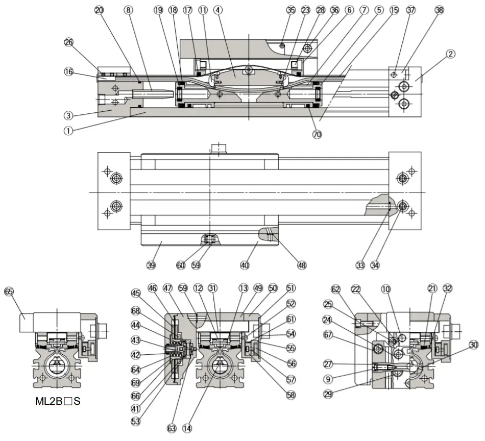
| No. | Description | Material | Qty. | Note |
| 1 | Cylinder tube | Aluminum alloy | 1 | Hard anodized |
| 2 | Head cover WR | Aluminum alloy | 1 | Hard anodized |
| 3 | Head cover WL | Aluminum alloy | 1 | Hard anodized |
| 4 | Piston yoke | Aluminum alloy | 1 | Anodized |
| 5 | Piston | Aluminum alloy | 2 | Hard anodized |
| 6 | End cover | Special resin | 2 | |
| 7 | Wear ring | Special resin | 2 | |
| 8 | Cushion ring | Aluminum alloy | 2 | Anodized |
| 9 | Cushion needle | Carbon steel | 2 | Nickel plated |
| 10 | Stopper | Carbon steel | 4 | Nickel plated |
| 11 | Belt separator | Special resin | 2 | |
| 12 | Guide roller | Special resin | 1 | |
| 13 | Parallel pin | Carbon steel | 1 | |
| 14 | Seal belt | Special resin | 1 | |
| 15 | Dust seal band | Stainless steel | 1 | |
| 16 | Belt clamp | Special resin | 2 | |
| 17 | Scraper | NBR | 2 | |
| 18 | Piston seal | NBR | 2 | |
| 19 | Cushion seal | NBR | 2 | |
| 20 | Tube gasket | NBR | 2 | |
| 21 | Bearing | Special resin | 2 | |
| 22 | Spacer | Stainless steel | 4 | |
| 23 | Spring pin | Carbon steel | 2 | |
| 24 | Hexagon socket head cap screw | Carbon steel | 6 | Chromated |
| 25 | Hexagon socket button head screw | Carbon steel | 4 | Chromated |
| 26 | Hexagon socket head set screw | Carbon steel | 8 | Chromated |
| 27 | 0-ring | NBR | 2 | |
| 28 | Double round parallel key | Carbon steel | 2 | |
| 29 | Hexagon socket head taper plug | Carbon steel | 6 | Chromated |
| 30 | Magnet | — | 2 | |
| 31 | Top cover | Stainless steel | 1 | |
| 32 | Side scraper | Special resin | 2 | |
| 33 | 0-ring | NBR | 4 | |
| 34 | Hexagon socket head taper plug | Carbon steel | 4 | Chromated |
| 35 | Phillips truss head screw | Carbon steel | 4 | Chromated |
| No. | Description | Material | Qty. | Note |
| 36 | Hexagon socket head cap screw | Carbon steel | 3 | Chromated |
| 37 | Parallel pin | Stainless steel | 4 | |
| 38 | Tension plate | Carbon steel | 4 | Nickel plated |
| 39 | Side cover L | Aluminum alloy | 1 | Hard anodized |
| 40 | Side cover R | Aluminum alloy | 1 | Hard anodized |
| 41 | 0-ring | NBR | 2 | |
| 42 | 0-ring | NBR | 2 | |
| 43 | Brake shoe | Sintered metal | 4 | |
| 44 | Brake plate | Stainless steel | 1 | Hard chrome plated |
| 45 | Diaphragm shell | Stainless steel | 4 | |
| 46 | Diaphragm | NBR | 2 | |
| 47 | Brake body | Aluminum alloy | 1 | Hard anodized |
| 48 | 0-ring | NBR | 1 | |
| 49 | Slide table | Aluminum alloy | 1 | Hard anodized |
| 50 | Sensor body | Aluminum alloy | 1 | Chromated |
| 51 | Connector gasket | NBR | 1 | |
| 52 | Round head Phillips screw | Carbon steel | 2 | Chromated |
| 53 | Brake guide | Carbon steel | 2 | Gas soft treated |
| 54 | Connector cover A/B | Carbon steel | 1 | Chromated |
| 55 | Sensor guide | Sintered metal | 1 | |
| 56 | Scale plate | Carbon steel | 1 | Nickel plated |
| 57 | Hexagon socket head cap screw | Carbon steel | 2 | Chromated |
| 58 | Sensor unit | — | 1 | |
| 59 | 0-ring | NBR | 6 | |
| 60 | Joint valve | Stainless steel | 1 | |
| 61 | Sensor holder | Stainless steel | 1 | |
| 62 | Hexagon socket head cap screw | Carbon steel | 8 | Chromated |
| 63 | Cross recessed countersunk head screw | Carbon steel | 4 | Chromated |
| 64 | Brake spring | Carbon steel | 2 | |
| 65 | Side plate | Aluminum alloy | 1 | Chromated |
| 66 | 0-ring | NBR | 2 | |
| 67 | Hexagon socket head cap screw | Carbon steel | 8 | Chromated |
| 68 | Diaphragm nut | Carbon steel | 2 | Chromated |
| 69 | Brake holder | Carbon steel | 2 | Gas soft treated |
| 70 | Lube-retainer | Special resin | 2 |
Chapter 10: Cushion Capacity
10-1 Selection of cushion
<Air cushion>
Standard Hyrodless Monosashikun is equipped with an air cushion.
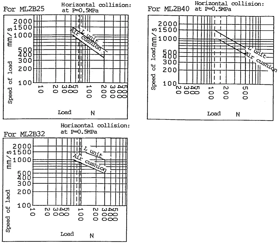
Air cushion is installed not to operate piston at low speed when piston approaches to stroke end, but to avoid shock when piston with large kinetic energy stops at stroke end. The range of load and speed absorbed by air cushion is within the limit line of air cushion in graph.
<Stroke adjustment unit with shock absorber>
This is used on the occasion when operating with load and speed of over the limit line of air cushion or when cushion is needed out of the air cushion stroke range due to stroke adjustment.
<L-Unit>
This is used on the occasion when cushion is needed out of the air cushion stroke range although load and speed are within the limit line of air cushion or when operating with the range of load and speed of over the air cushion limit line and below the unit limit line.
<Note>
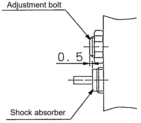
- Absorbing capacity of unit is for the occasion when all stroke of equipped shock absorber is used. When effective stroke becomes shorter due to stroke adjustment, absorbing capacity becomes extremely small. Therefore, fix adjustment bolt to project 0.5mm above shock absorber.

- When shock absorber is used in the range of air cushion stroke, air cushion needle shall be almost full opened (about one and a half turn from the position of full close.)
Air cushion stroke Unit : mm Bore size (mm) Cushion stroke φ25 15 φ32 19 φ40 24
10-2 Absorbing capacity of air cushion and stroke adjustment unit
Stroke adjustment unit
| Torque for bolt | unit : N.m |
| Bore size (mm) | Torque |
| 25 | 3 |
| 32 | 5 |
| 40 | 10 |
Stroke adjustment unit lock plate
| Torque for bolt | unit : N.m |
| Bore size (mm) | Torque |
| 25 | 1.2 |
| 32 | 3.3 |
| 40 | 3.3 |
Stroke adjustment unit with shock absorber
Calculation of absorbing energy
| Type of collision | Horizontal collision | Vertical collision (descent) | Vertical collision (ascent) |
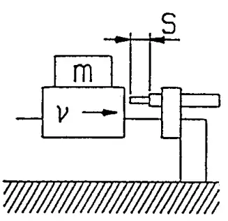 | 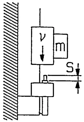 |  | |
| Kinetic energy E1 | ½ m・v² | ||
| Thrust energy E2 | F・s | F・s + m・g・s | F・s – m・g・s |
| Absorption energy E | E1 + E2 | ||
V: Speed of load (m/s)
m: Weight of load (kg)
F:Thrust of cylinder (N)
g: Gravitational acceleration (9.8m/s)
s: Stroke of shock absorber (m)
Note) Speed of load is the speed of the moment when load collides with shock absorber.
10-2 Adjusting Method
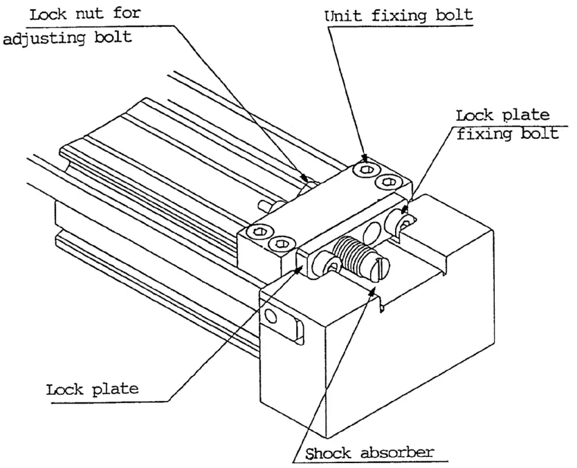
<Travel and fix of unit body>
Unit body can be travelled by loosening 4 pieces of bolt. Unit body can be fixed by tightening unit body evenly with 4 pieces of bolt at the specific position. The position, however, may got out of the position depending on the energy size for collision. Mounting brackets for adjusting holder are provided for –X416 and –X417. For the length of your request other than that, please consult with us separately. (See bolt torque for fixing stroke adjusting unit.)
<Stroke adjustment of adjusting bolt>
Loosen lock nut for adjusting bolt and fix with lock nut after adjusting stroke with wrench from lock plate side.
<Stroke adjustment of shock absorber>
After adjusting stroke by loosening two pieces of lock plate fixing bolt to turn shock absorber, fix shock absorber by tightening lock plate fixing bolt evenly. On this occasion, care shall be taken so that bolts are not tightened too much. (Please refer to torque for stroke adjustment unit lock plate bolt.)
Note) Although there are some cases where a little bend will be caused on lock plate due to tightening of lock plate bolt, it does not affect on shock absorber and locking function.
Chapter 11: Stopping Operation
11-1 Overrun (ML2 + Sequence controller)
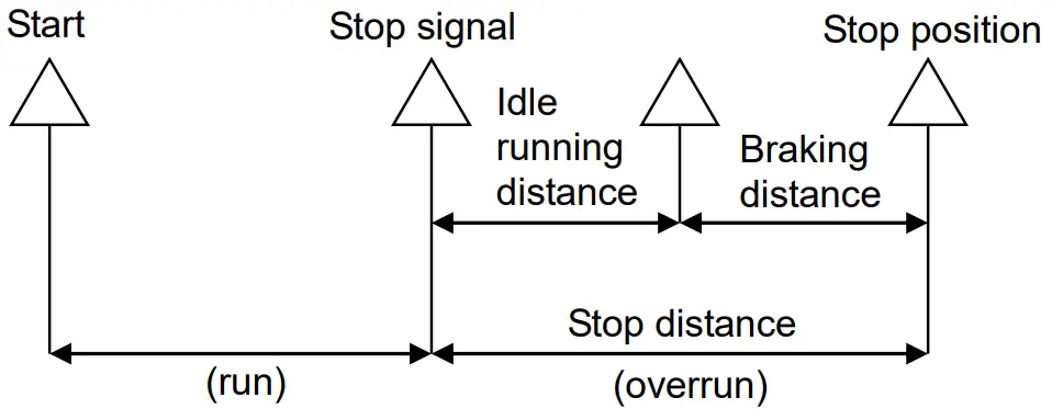
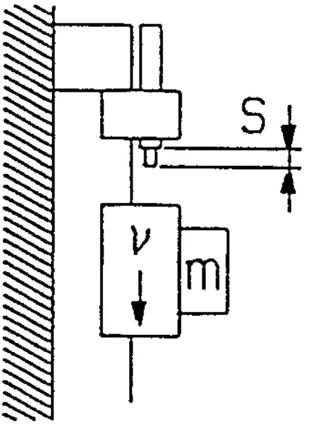
When cylinder is stopped intermediately, “idle running distance” (from detection of stop signal to beginning of brake operation) and “braking distance “(from beginning of brake operation to slider stop) are occurred as shown in the figure left.
The graph below shows the relation between piston speed and overrun.
(The length of overrun is changed by piston speed, load, tubing condition and control method. Be sure to adjust the stop signal position, etc. by trial operation with the actual machine.)
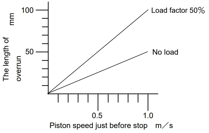
Operating pressure 0.5MPa
Brake releasing pressure 0.3MPa
Mounting position Horizontal
11-2 Dispersion of stopping position
When cylinder is stopped intermediately, the stopping position is not fixed.
Dispersion of stopping position is changed by piston speed, load, tubing condition and control method, etc. Please refer to the table below.
| Piston speed just before stop mm/s | 100 | 300 | 500 | 800 | 1000 |
| Stopping accuracy mm | ±0.5 | ±1.0 | ±2.0 | ±3.0 | ±4.0 |
Conditions
Operating pressure 0.5MPa
Brake releasing pressure 0.3MPa
Load factor 25%
ML2 + CEU2
| Piston speed just before stop mm/s | 500mm/s |
| Stopping accuracy mm | ±0.5 |
Chapter 12: Manual Operating Procedure
[Brake release]
- Supply brake releasing pressure of 0.3~0.5MPa from brake releasing port on slider side.
- Thread bolt into manual port on slider side.
- Exhaust brake releasing air.
[Brake operation]
- Supply brake releasing pressure of 0.3~0.5MPa from brake releasing port on slider side.
- Remove bolt threaded into manual port.
- Exhaust brake releasing air.
 Bolt for manual release
ML2B25 M5×0.8 L=8 ML2B32 M6×1 L=10 ML2B40 M8×1.25 L=12
 Bolt for manual release
Chapter 13: Installation & Wiring
13-1 Installation of Cylinder
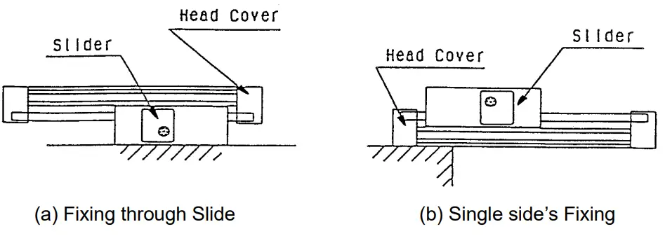
- It should be installed at high flatness surface. For uneven surface. Shim adjustment should be done to achieve smooth operation of slider with a minimum operating pressure of 0.1MPa.
- Installed with utilizing both sides head cover. Do not fix cylinder’s position through slider, as shown in diagram (a). With overloading the bearing, operation error occurs.
Besides that, for the case of single sided fixing method (as refer in diagram (b), consultancy should be made, due to bending of tube may occur and thus, lead to the occurs of operation error. There are 2 ways, as shown in diagram below, to fix cylinder’s position.
Utilizing the installation method, with the consideration of mounting surface and situation.
(Side support, option, should be used for support purposes only.)
- With loading within allowable range of Hyrodless Monosashikun, supporting structure (LM Guide) is still necessary to be installed as a support for the applied loading. Besides that, for the case of long stroke, floating structure design should be brought in to overcome misalignment problem.
- Cylinder has to be covered when it is used at environment that has chips, dust, oil mist and etc.
- Be aware of not to harm (dented marks and etc.) the outer surface of cylinder tube, which will lead to the damage of bearing and scraper. Consequently, dis operation will occur. Bessie that, be aware of not to apply too much of impact and momentum upon slider as slider is only supported by plastic made bearing.
- Do not apply load onto brake and scale plate, its bending will lead to operation error. Once, brake and scale plate have been adjusted during installation state. Re-adjustment is not required and should be avoided.
Note: Grease used are lithium based grease with concentration class 1 or 2.
 There are 2 ways, as shown in diagram below, to fix cylinder’s position.
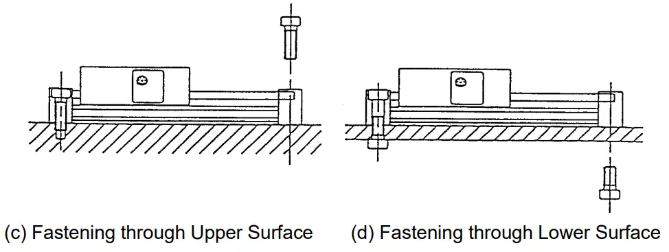
- Hyrodless Monosashikun uses magnetic sensor to detect position. Therefore, if strong magnetic field appears nearby, operation error will occur.
Surrounding magnetic field should be below than 14.5mT.
Note: 14.5mT magnetic field will be just as the same as the resulted magnet field from 15,000A welding current’s welding machine (within 18cm). To prevent from the effect of magnetic field, sensor should be covered by magnetic material.
- Prevent sensor unit from contacting with water, oil and etc.
- Do not install Hyrodless Monosashi-kun near to motor, welding machine, and others facility which will produce noise, which will cause counter malfunction.
Besides that, separate the power line from others.
The longest transmission distance for Hyrodless Monosashi-kun is 20m. Wiring above than the figure, should be taken noted at.
13-2 Electrical Wiring
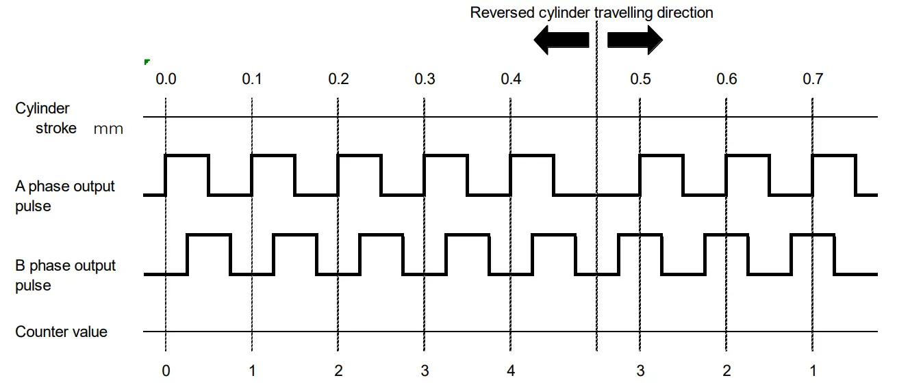
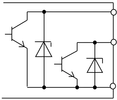
Output method
Output signal of Hyrodless Monosashi-kun is phase difference output of A phase / B phase (op collector output) as shown in the figure below.
1 pulse signal is sent to both output terminals A and B at every 0.1mm travel of Hyrodless Monosahi-kun.
Also maximum response time of sensor for Hyrodless Monosashi-kun is maximum 1500 mm/s(15Kcps) in cylinder speed.
Input / Output
Input / Output of Hyrodless Monosashi-kun is performed by connector came from sensor.
Signal
| Symbol of contact | Signal |
| A | A phase |
| B | B phase |
| C,D | COM (0V) |
| E | 12V (Power supply) |
| F | 0V (Power supply) |
| G | GND (Shield) |
 A phase (white)
B phase (yellow)
COM (0V) (brown, blue)
Output circuit of Hyrodless Monosashi-kun
13-3 Connection of Extension Cable
Use specified (SMC) extension cable. Cable length is 5m – 20m with interval of 5m. For the distance of more than 20m, use specified transmission box (Model No.: CE1-H0374).
*Example of cable connection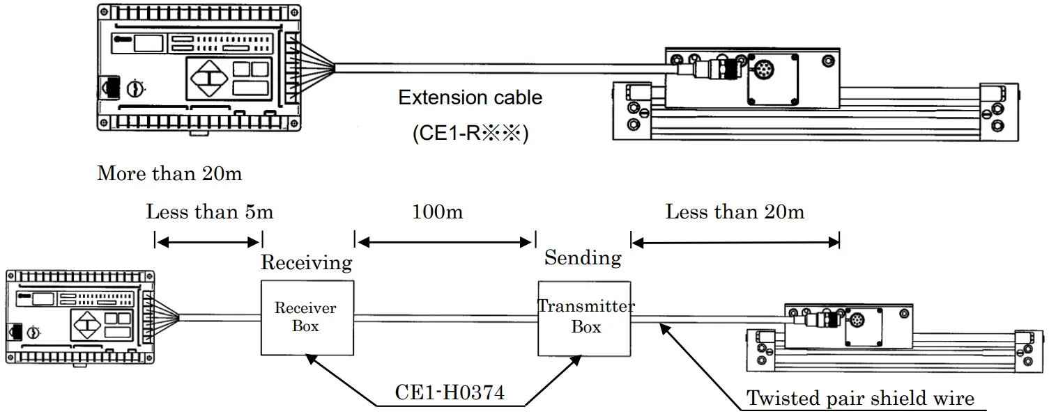 *Note
*Note
- Clamp and fix the connector and sensor connection to reduce tension acting on them.
- Separate cable with power line or other lines which make noise.
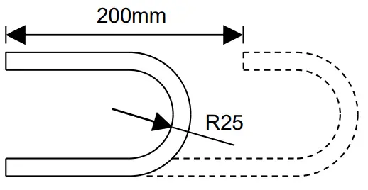
- When cable is necessary to have U-shaped bend, set the bending radius to be above 25mm. Bending performance: According to the drawing shown below, life span about 4 million cycle can be achieved.
 Reciprocating with bending speed 100 times/min.
 Reciprocating with bending speed 100 times/min.
![]() Doc. No. CE※-OMP0016-B
Doc. No. CE※-OMP0016-B


