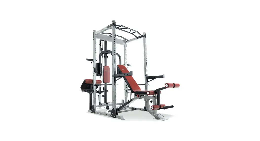
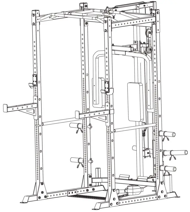
![]() HG-SM3110 Smith Machine
HG-SM3110 Smith Machine
Instruction Manual
 Assembly & User Instructions
Please keep for future reference
Important – Please read these instructions fully before assembly or use
These instructions contain important information which will help you get the best from your equipment and ensure safe and correct assembly, use and maintenance.
If you need help or have damaged or missing parts, Contact the manufacturer for help.
Safety Information
To reduce the risk of serious injury, read the entire manual before you assemble or use your home gym. In particular, note the following safety precautions.
Assembly
- Check you have all the components and tools listed in the parts list, bearing in mind that, for ease of assembly, some components are preassembled.
- Keep children and animals away from the exercise area, small parts could pose a choking hazard if swallowed.
- Make sure you have enough space to layout the parts before starting.
- Assemble the item as close to its final position (in the same room) as possible.
- The product must be installed on a stable and level surface.
- Dispose of all packaging carefully and responsibly.
Using
- Keep unsupervised children away from the equipment.
- Injuries to health may result from incorrect or excessive training.
- If any of the adjustment devices are left projecting, they could interfere with the user’s movement.
- It is the responsibility of the owner to ensure that all users of this product are properly informed as to how to use this product safely.
- This product is intended for domestic use only. Do not use in any commercial, rental, or institutional setting.
- Before using the equipment to exercise, always perform stretching exercises to properly warm up.
- If the user experiences dizziness, nausea, chest pain, or other abnormal symptoms stop the workout and seek immediate medical attention. •Only one person at a time should use the equipment.
- Keep hands away from all moving parts.
- Always wear appropriate workout clothing when exercising. Do not wear loose or baggy clothing, as it may get caught in the equipment. Wear trainers to protect your feet while exercising.
- Do not place any sharp objects around the equipment.
- Disabled persons should not use the equipment without a qualified person or doctor in attendance.
- Keep this equipment indoors, away from moisture and dust. Do not put the equipment in a garage, outbuilding, covered patio, or near water.
- If children are allowed to use the equipment under supervision, their mental and physical development should be taken into account. They should be controlled and instructed to the correct use of the equipment. The equipment is under no circumstances suitable as a toy.
- This product is suitable for a maximum user weight of: 120 kgs.
- This product is not suitable for therapeutic purposes.
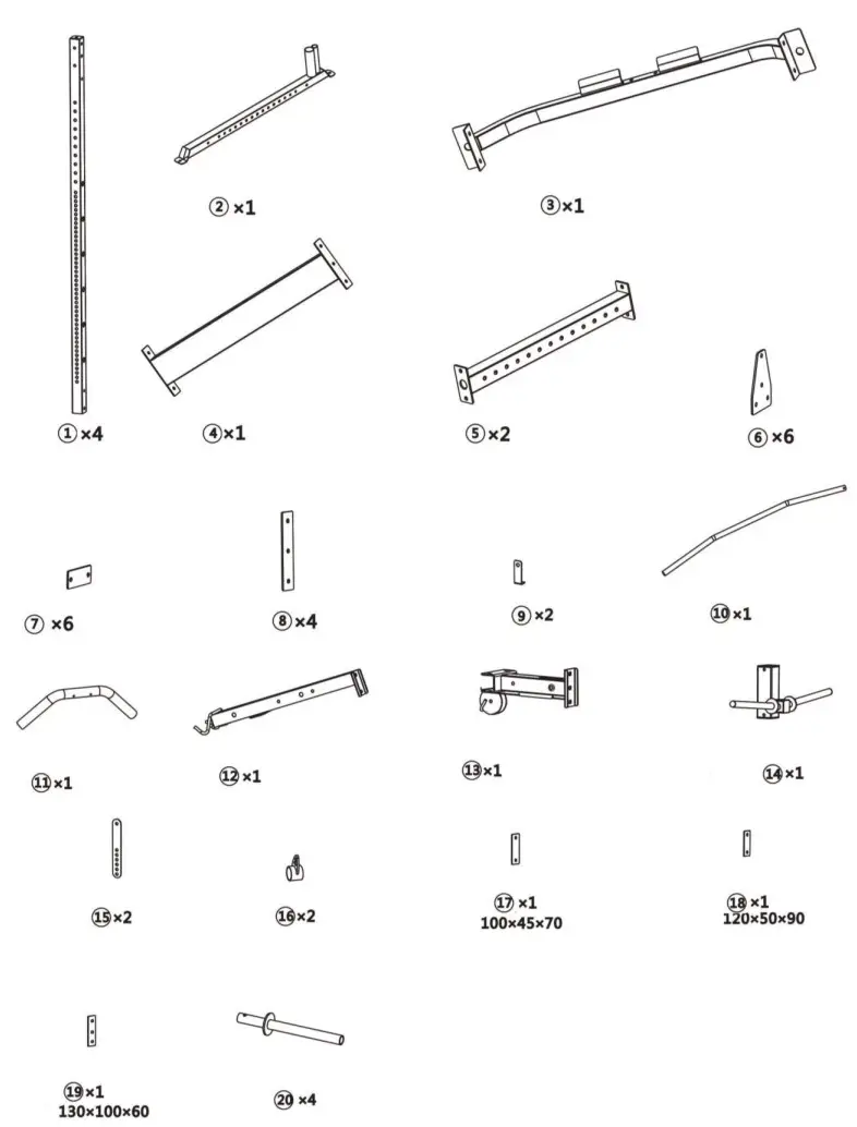
Components-parts 1
 Components-parts (2)
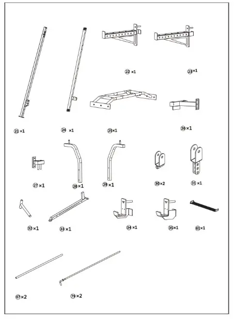
Components-parts (3)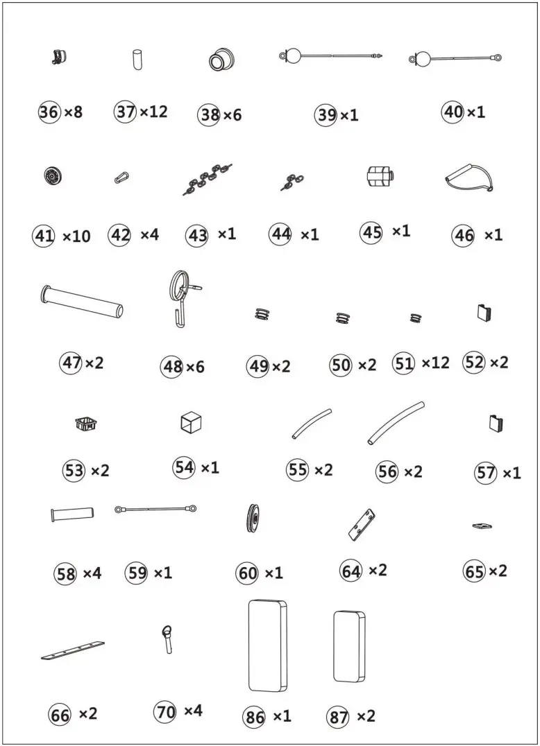
Components-fixings (1)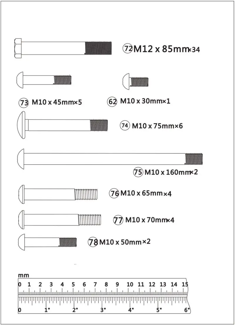
Components-fixings (2)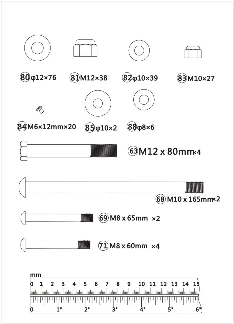
Assembly Instructions
Tools: Adjustable spanner x 2
Attention:
It is strongly recommended to assemble the equipment by two or more people, otherwise it may cause serious injury.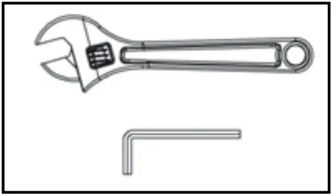 The icon indicates the spanner can be directly used to tighten and secure during assembly.
 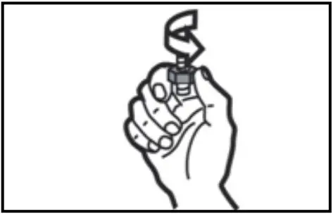 The icon indicates turn the bolt by hand during assembly, but do not tighten them so as not to affect next assembly step.
 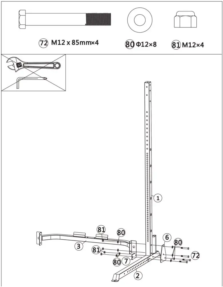 Step 1
Attach the 1 x Vertical Frame (#1), 1 x Lower Connection Frame (#3), 1 x Triangle Plate (#6) and 1 x Bracket (#7) to the Base Frame (#2) using 4 x M12x85mm Hex Bolts (#72), 8 x 12mm Washers (#80) and 4 x M12 Aircraft Nuts (#81).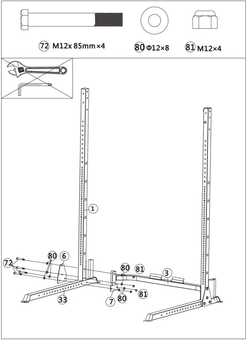 Step 2
Attach the 1 x Vertical Frame (#1), 1 x Lower Connection Frame (#3), 1 x Triangle Plate (#6) and 1 x Bracket (#7) to the Left Base Frame (#33) using 4 x M12x85mm Hex Bolts (#72), 8 x 12mm Washers (#80) and 4 x M12 Aircraft Nuts (#81). 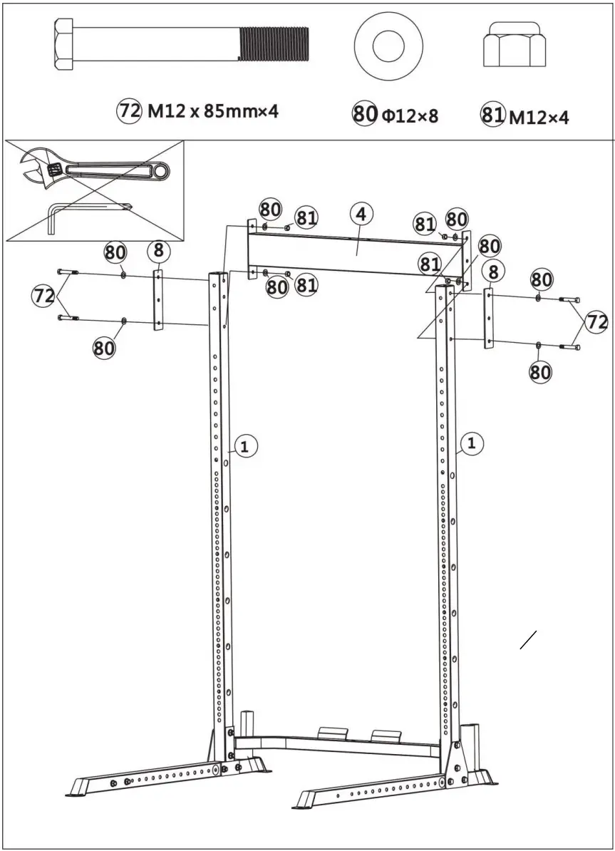 Step 3
Attach 1 x Upper Frame (#4) and 2 x Long Plates (#8) to 2 x Vertical Frames (#2) using 4 x M12x85mm Hex Bolts (#72), 8 x 12mm Washers (#80) and 4 x M12 Aircraft Nuts (#81). 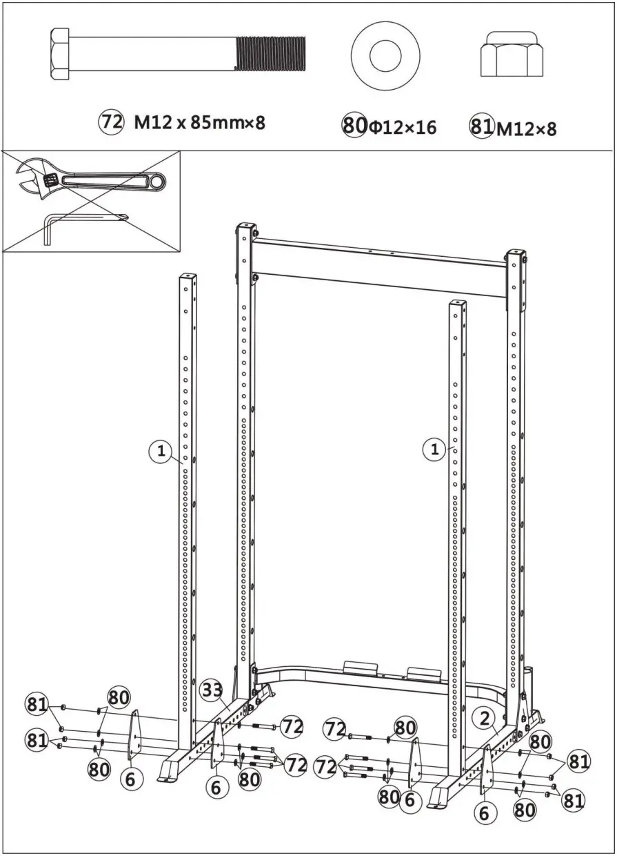 Step 4
Fix the Vertical Frame (#1), Base Frame (#2), Left Base Frame (#33) and 4 x Triangle Plates (#6) together using 8 x M12x85mm Hex Bolts (#72), 16 x 12mm Washers (#80) and 8 x M12 Aircraft Nuts (#81).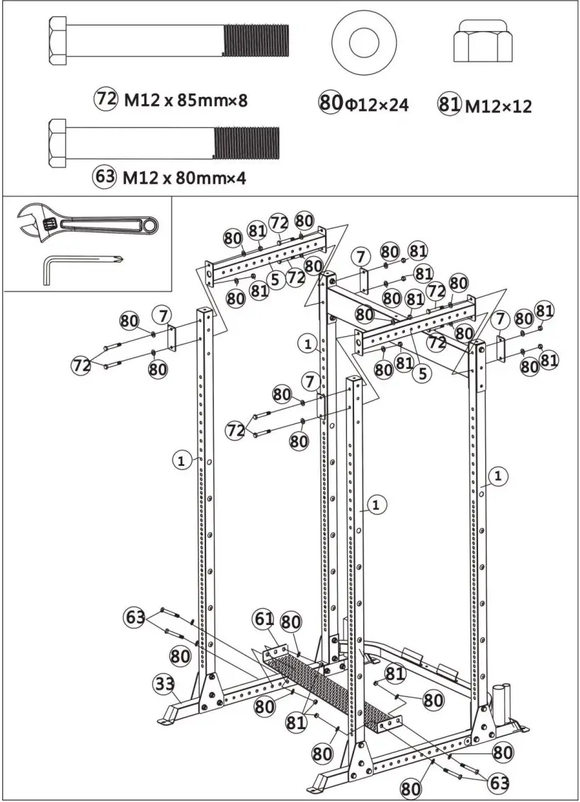 Step 5
Attach 2 x Side Connection Frames (#5) to the Vertical Frames (#1) using 8 x M12x85mm Hex Bolts (#72), 16 x 12mm Washers (#80), 4 x M12 Aircraft Nuts (#81) and 4 x Brackets (#7).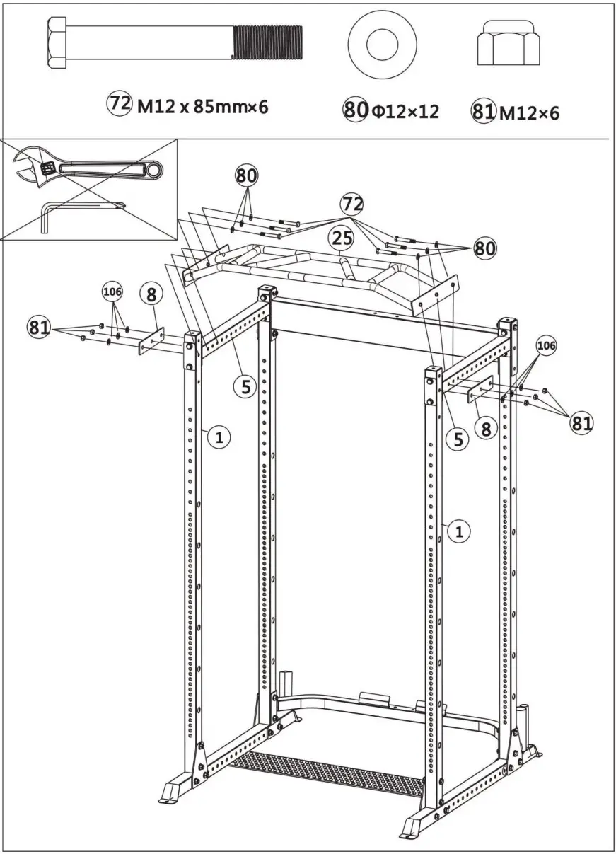 Step 6
Attach the Trapezoid Lat Pull Frame (#25) to the Side Connection Frame (#5) and Vertical Frame (#1) using 6 x M12x85mm Hex Bolts (#72), 12 x 12mm Washers (#80), 6 x M12 Aircraft Nuts (#81) and 2 x Long Plates (#8).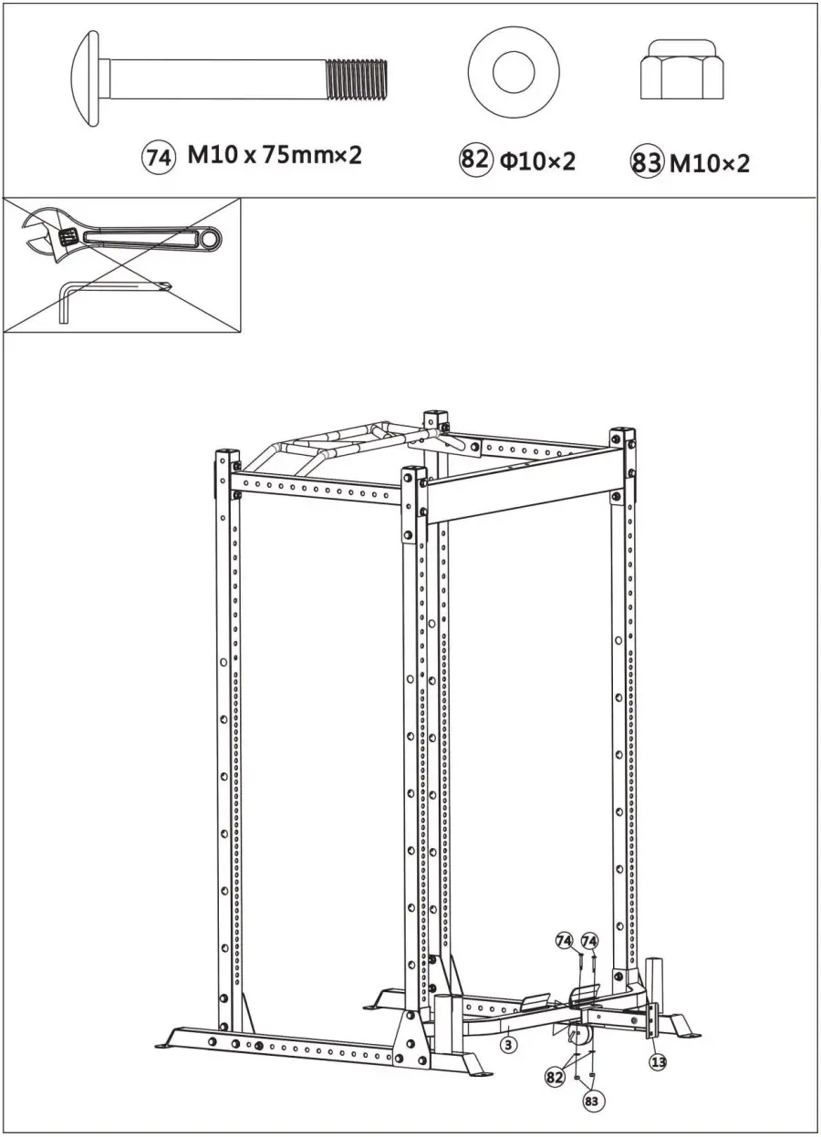
Step 7
Attach the Lat Pull Lower Frame (#13) to the Lower Connection Frame (#3)using 2 x M10x75mm Carriage Bolts (#74), 2 x 10mm Washers (#82) and 2 x M10 Aircraft Nuts (#83).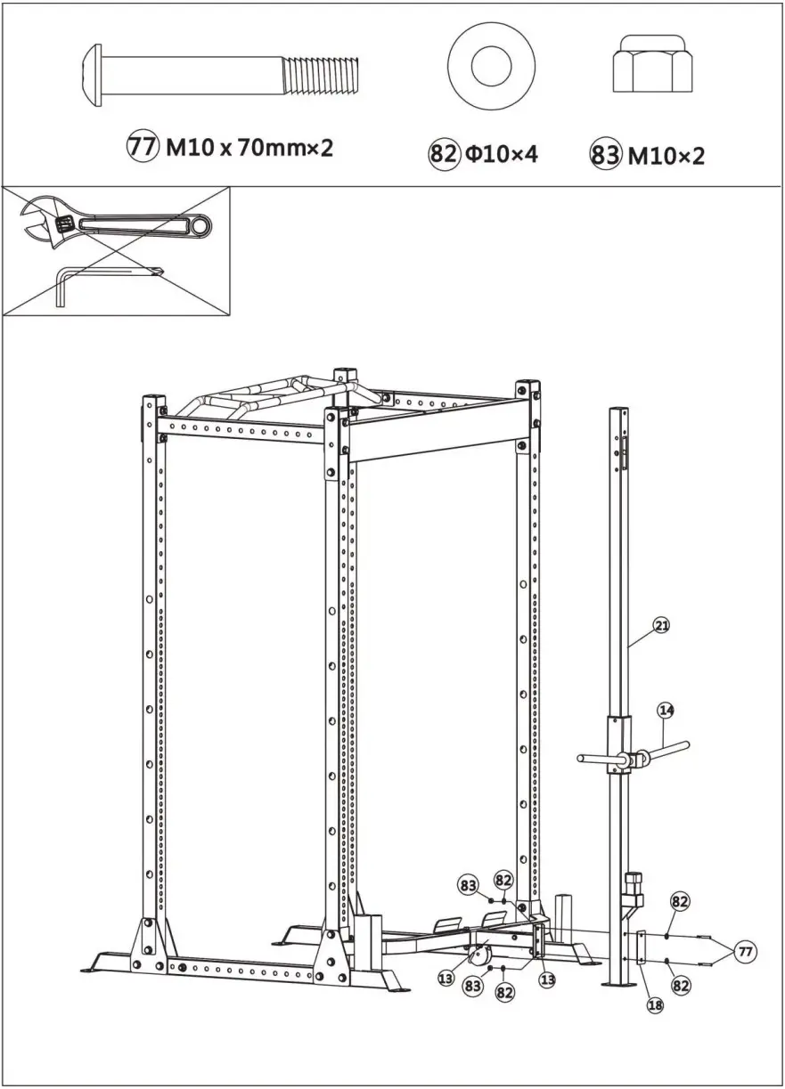 Step 8
- Attach the Lat Pull Frame (#21)to the Lat Pull Lower Frame (#13) using 2 x M10x70mm Allen Bolts (#77), 4 x 10mm Washers (#82), 2 x M10 Aircraft Nuts (#83) and 1 x Bracket (#18).
- Put the Rear Sliding Sleeve Frame (#14) onto the Lat Pull Vertical Frame (#21).
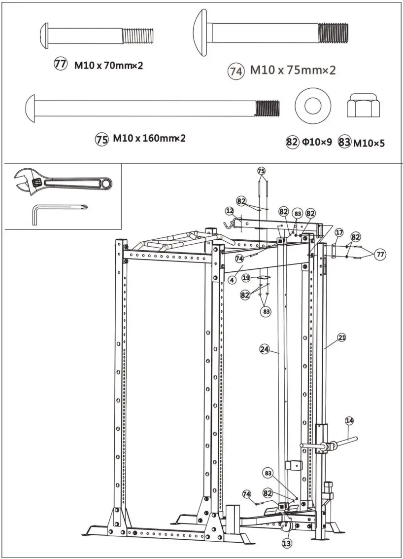 Step 9
- Attach the Butterfly Vertical Fixed Frame (#24) to the Lat Pull Upper Frame (#12) and Lat Pull Lower Frame (#13) using 2 x M10x75mm Carriage Bolts (#74), 2 x 10mm Washers (#82) and 2 x M10 Aircraft Nuts (#83).
- Attach the Pull Upper Frame (#12) to the Upper Connection Frame (#4) using 2 x M10x160mm Allen Bolts (#75), 4 x 10mm Washers (#82), 2 x M10 Aircraft Nuts (#83) and 1 x Bracket (#19).
- Attach the Pull Upper Frame (#12) to the Lat Pull Vertical Frame (#21) using 2 x M10x70mm Allen Bolts (#77), 3 x 10mm Washers (#82), 1 x M10 Aircraft Nuts (#83) and 1 x Bracket (#17).
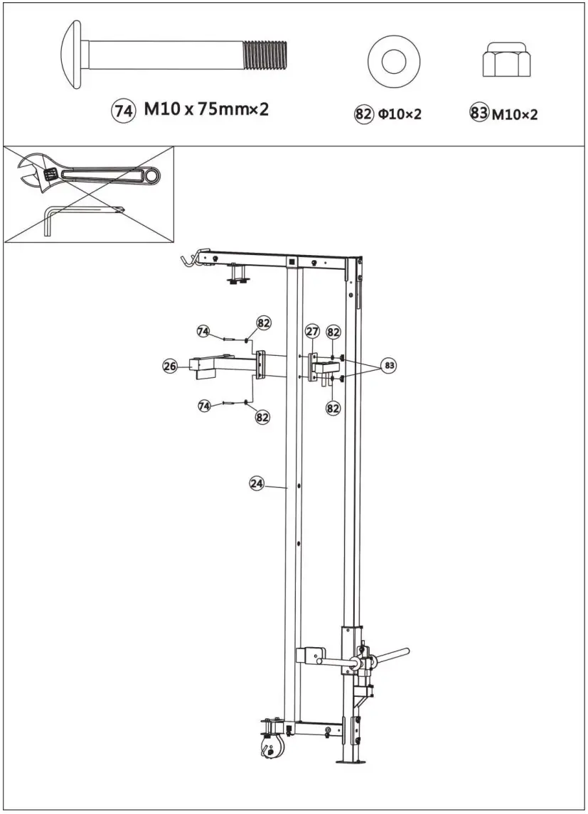 Step 10
Attach the Butterfly Front Fixed Frame (#26) and Butterfly Rear Fixed Frame (#27) to the Butterfly Vertical Fixed Frame (#24) using 2 x M10x75mm Carriage Bolts (#74), 2 x 10mm Washers (#82), 2 x M10 Aircraft Nuts (#83).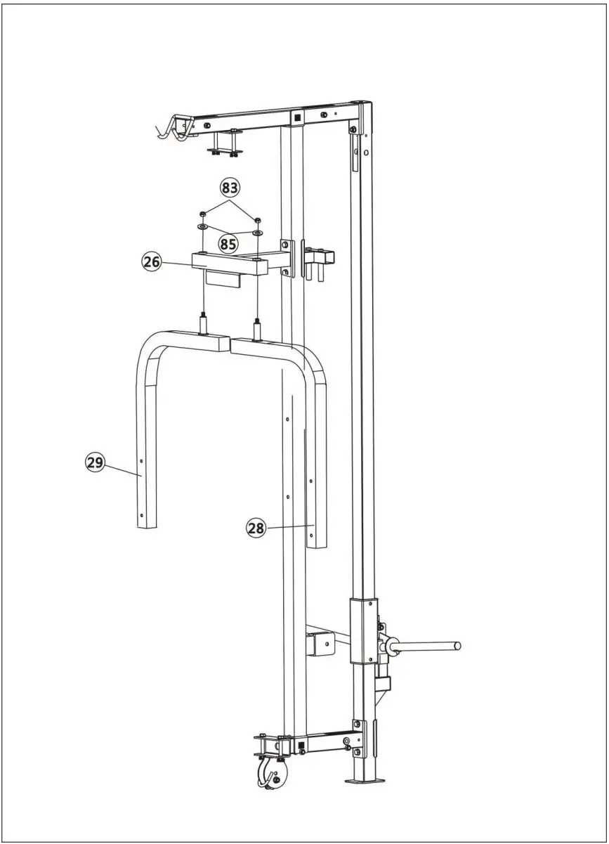 Step 11
Attach the Left &Right Butterfly Frame (#28 & #29) to the Butterfly Front Fixed Frame (#26) using 2 x φ25×φ10.5×б1.5 Washer (#85) and 2 x M10 Aircraft Nuts (#83).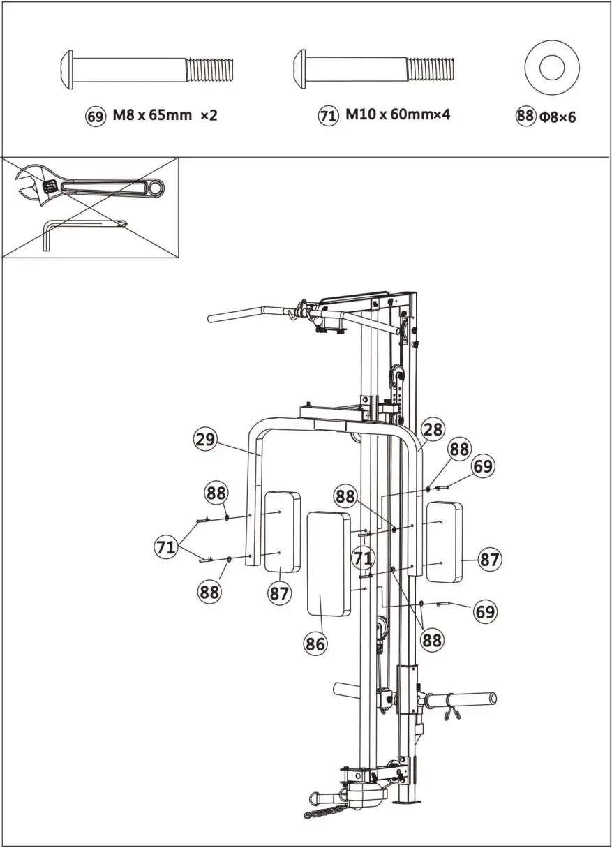 Step 12
- Attach the Backrest Pad (#86) to the Butterfly Vertical Fixed Frame (#24) using 2 x M8x65mm Allen Bolts (#69).
- Attach the Arm Curl Pad (#87) to the Left &Right Butterfly Frame (#28 & #29) using 2 x M8x60mm Allen Bolts (#71).
 Step 13
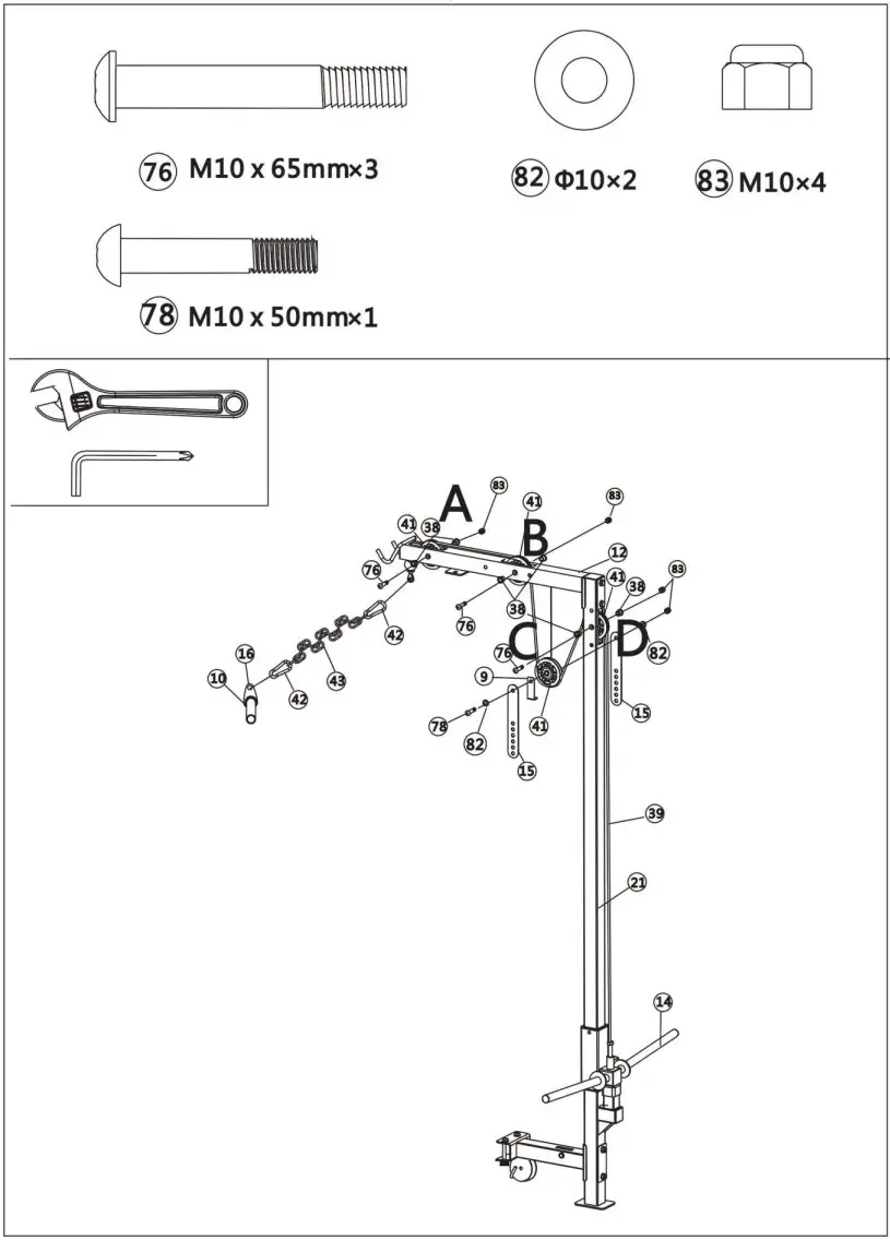
- Attach the Lat Pull Cable (#39) the position A and B of the Lat Pull Upper Frame (#12) using 2 x M10 x65mm Allen Bolts (#76), 4 x Pulley Bush (#38), 2 x M10 Aircraft Nuts (#83) and 2 x 97# Pulleys (#41).
- Fix 2 x Double Pulley Brackets (#15), 1 x L-Shape Plate (#9), 1 x 97# Pulley (#41) and Lat Pull Cable (#39) to the position C using 1 x M10x50mm Allen Bolt (#78), 2 x 10mm Washers (#82) and 1 x M10 Aircraft Nut (#83).
- Fix the Lat Pull Cable (#39) to the Lat Pull Vertical Frame (#21) using 1 x M10x65mm Allen Bolt (#76),2 x Pulley Bushes (#38), 1 x M10 Aircraft Nut (#83) and 1 x 97# Pulley (#41).
- Fix the Lat Pull Cable (#39) to the Rear Sliding Frame (#14).
- Respectively fix each end of the 15 Joints Chain (#43) to the Hook Frame (#16) and Lat Pull Cable (#39) using 2 x 7# Gourd Hook (#42).
 Step 14
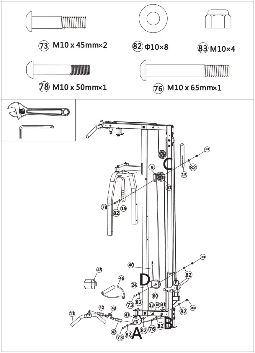
- Fix 1 x 97# Pulley (#41) and Lower Pull Cable (#40) to the position A using 1 x M10 x45mm Allen Bolts (#73), 2 x 10mm Washers (#82) and 1 x M10 Aircraft Nut (#83).
- Fix 1 x 97# Pulley (#41) and Lower Pull Cable (#40) to the position B using 1 x M10x65mm Allen Bolt (#76), 2 x 10mm Washers (#82) and 1 x M10 Aircraft Nut (#83).
- Fix 2 x Double Pulley Brackets (#15), 1 x L-Shape Plate (#9), 1 x 97# Pulley (#41) and Lower Pull Cable (#40) to the position C using 1 x M10x50mm Allen Bolt (#78), 2 x 10mm Washers (#82) and 1 x M10 Aircraft Nut (#83).
- Fix 1 x 76# Pulley (#60) and Lower Pull Cable (#40) to the position D using 1 x M10x45mm Allen Bolt (#73), 2 x 10mm Washers (#82) and 1 x M10 Aircraft Nut (#83).
- Fix one end of the 6 Joints Chain (#44) to the Lower Pull Cable (#40) and fix another end to the Short Bar (#39) using 2 x 7# Gourd Hook (#42).
 Step 15
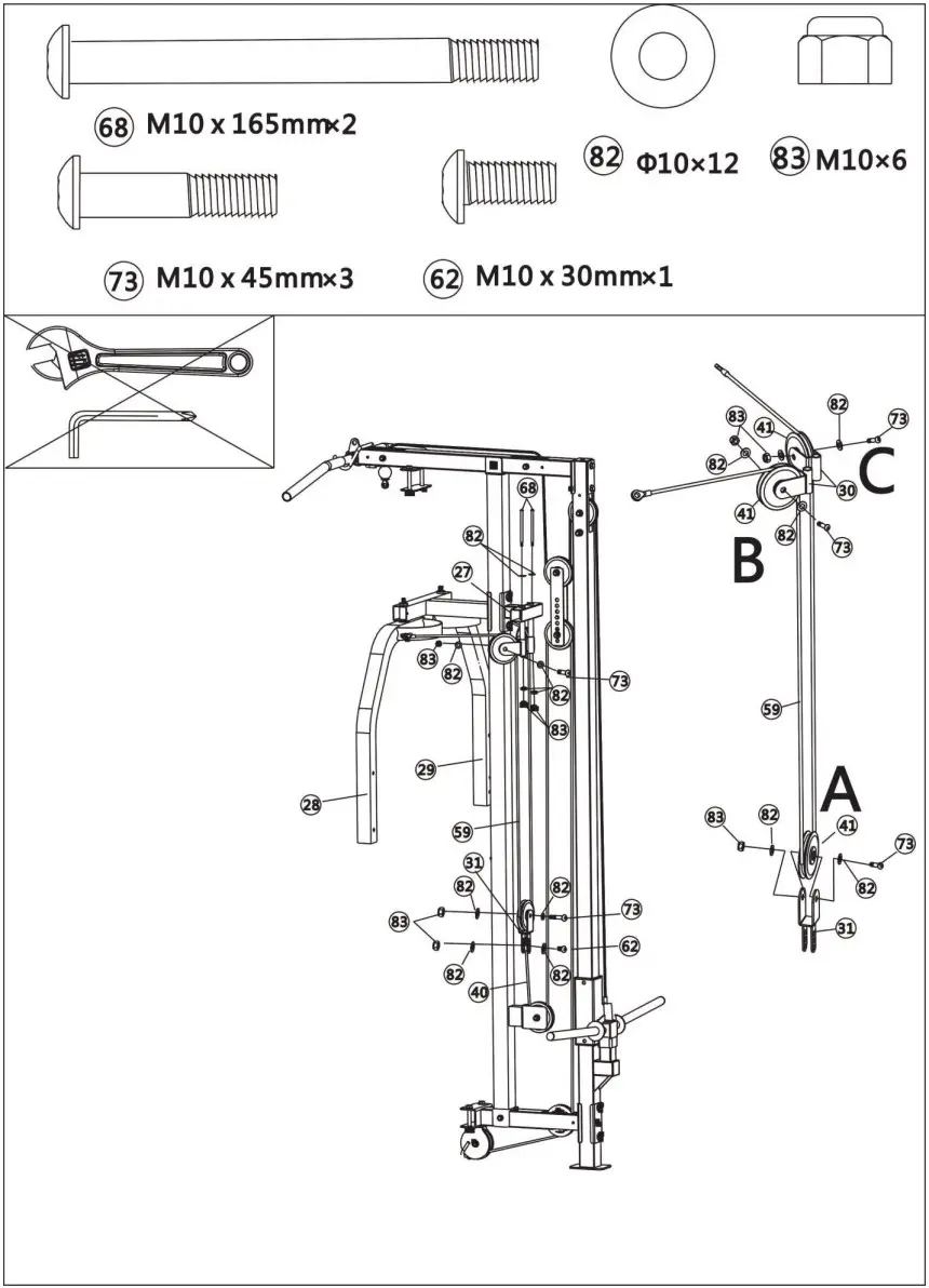
- Fix 2 x Swing Pulley Brackets (#30) to the Butterfly Rear Fixed Frame (#27) using 2 x M10x165mm Allen Bolts (#68), 4 x 10mm Washers (#82) and 2 x M10 Aircraft Nuts (83).
- Respectively hang each end of the Butterfly Cable (#59) to the Left Butterfly Frame (#28) and Right Butterfly Frame (#29).
- Fix 2 x 97# Pulleys (#41) and Butterfly Cable (#59) to the position BC using 2 x M10x45mm Allen Bolts (#73), 4 x 10mm Washers (#82) and 2 x M10 Aircraft Nuts (83).
- Fix 1 x 97# Pulley (#41) and Butterfly Cable (#59) to the position A using 1 x M10x45mm Allen Bolt (#73), 2 x 10mm Washers (#82) and 1 x M10 Aircraft Nut (83).
- Fix the Lower Pull Cable (#40) to the Adjustment Pulley Bracket (#31) using 1 x M10x30mm Allen Bolt (#62), 2 x 10mm Washers (#82) and 1 x M10 Aircraft Nut (83).
 Step 16
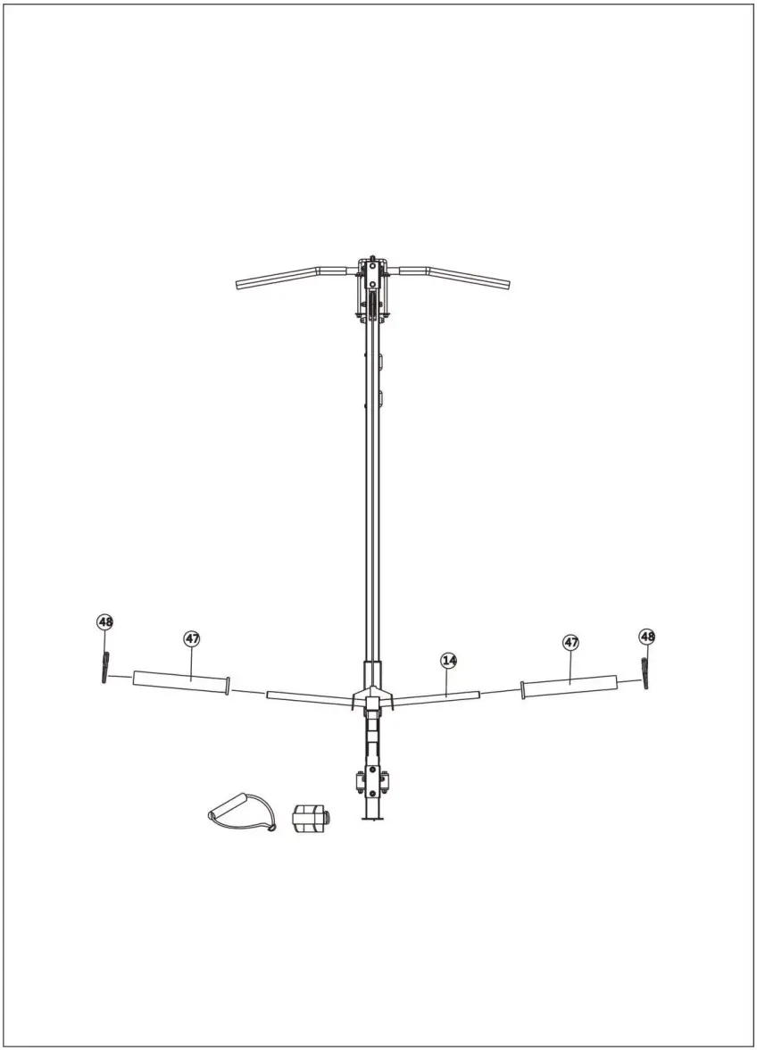
Put 2 x Sleeves (#47) onto both ends of the Rear Sliding Frame (#14) and align with φ49 Spring Collar (#48). 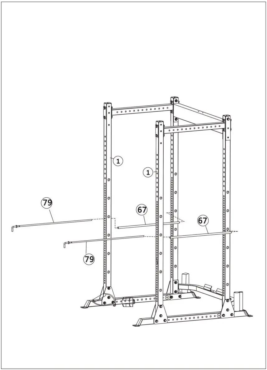
Step 17
Attach 2 x Safety Bar Sleeves (#67) to 2 x Vertical Frames (#1) using 2 x Safety Bars (#79). 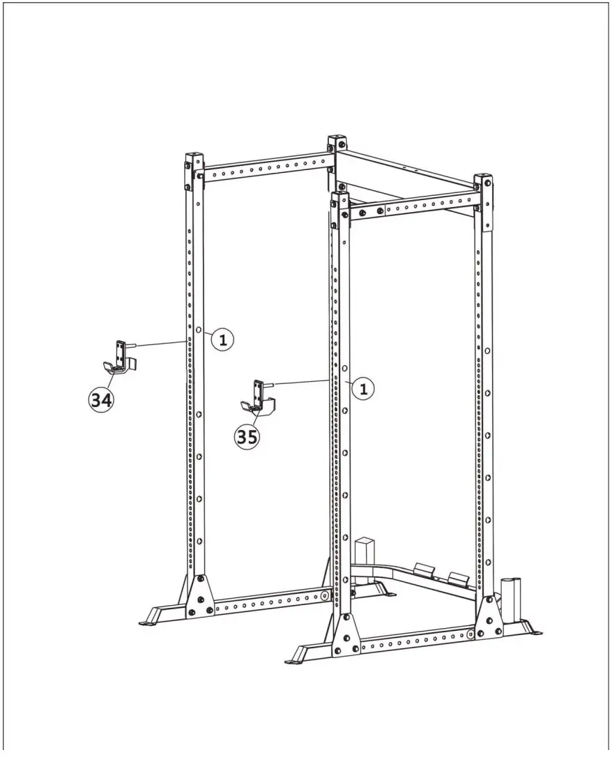
Step 18
Attach the Left Rack Frame (#34) and Right Rack Frame (#35) to the Vertical Frame (#1). 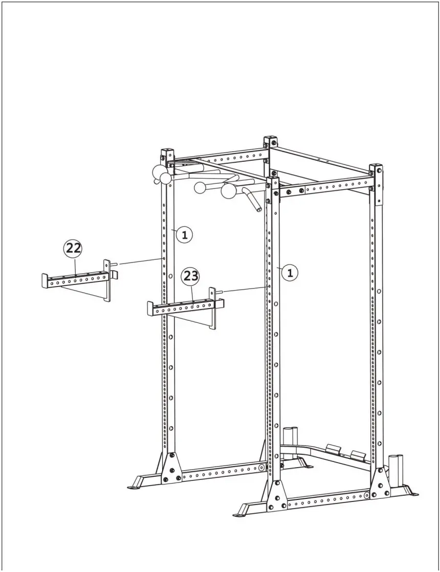 Step 19
Attach the Left Safety Rack Frame (#22) and Right Safety Rack Frame (#23) to the Vertical Frame (#1). 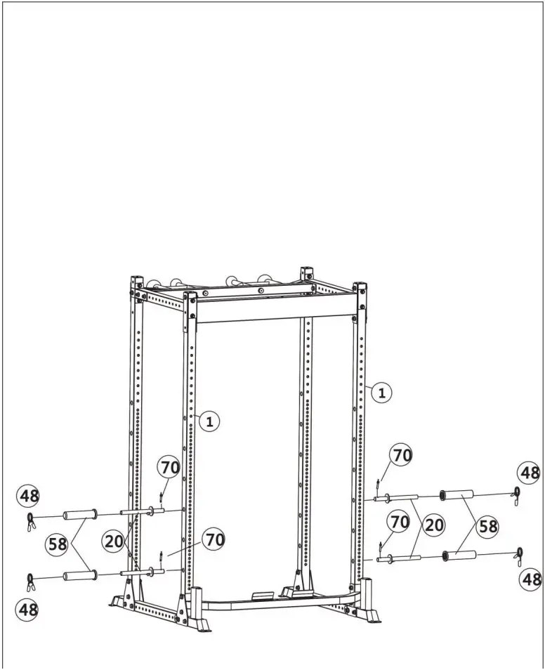 Step 20
- Insert 4 x Weight Plate Supports (#20) into the Vertical Frame (#1) and lock with 4 x φ8×40 Pins (#70).
- Put 2 x φ8×40 Spring Collars (#48) and 4 x φ50×200 Sleeves (#58) on the Weight Plate Supports (#20).
Parts Lis
| Part # | Description | QTY |
| 1 | Vertical Frame | 4 |
| 2 | Base Frame | 1 |
| 3 | Lower Connection Frame | 1 |
| 4 | Upper Connection Frame | 1 |
| 5 | Side Connection Frame | 2 |
| 6 | Triangle Plate | 6 |
| 7 | Bracket | 6 |
| 8 | Long Plate | 4 |
| 9 | L-Shape Bracket | 2 |
| 10 | Lat Bar | 1 |
| 11 | Short Bar | 1 |
| 12 | Lat Pull Upper Frame | 1 |
| 13 | Lat Pull Lower Frame | 1 |
| 14 | Rear Sliding Sleeve | 1 |
| 15 | Double Pulley Bracket | 2 |
| 16 | Hook Frame | 2 |
| 17 | Bracket 100×45×70 | 1 |
| 18 | Bracket 120×50×90 | 1 |
| 19 | Upper Plate 130×60×100 | 1 |
| 20 | Weight Plate Support | 4 |
| 21 | Lat Pull Vertical Frame | 1 |
| 22 | Left Safety Rack Frame | 1 |
| 23 | Right Safety Rack Frame | 1 |
| 24 | Butterfly Vertical Fixed Frame | 1 |
| 25 | Trapezoid Lat Pull Frame | 1 |
| 26 | Butterfly Front Fixed Frame | 1 |
| 27 | Butterfly Rear Fixed Frame | 1 |
| 28 | Left Butterfly Frame | 1 |
| 29 | Right Butterfly Frame | 1 |
| 30 | Swing Pulley Bracket | 2 |
| 31 | Adjustment Pulley Bracket | 1 |
| 32 | T-Shape Pin | 1 |
| 33 | Left Base Frame | 1 |
| 34 | Left Rack Frame | 1 |
| 35 | Right Rack Frame | 1 |
| 36 | Handle Ring | 8 |
| 37 | Circlip Sleeve | 12 |
| 38 | Pulley Bush | 6 |
| 39 | Lat Pull Cable | 1 |
| 40 | Lower Pull Cable | 1 |
| 41 | 97 Pulley | 10 |
| 42 | 7# Gourd Hook | 4 |
| 43 | 15 Joints Chain | 1 |
| 44 | 6 Joints Chain | 1 |
| 45 | Foot Strap | 1 |
| 46 | Single Strap | 1 |
| 47 | Sleeve φ50×φ26.5×300 | 2 |
| 48 | φ49 Spring Collar | 6 |
| 49 | φ25×1.5 End Cap | 2 |
| 50 | φ25×2 End Cap | 2 |
| 51 | φ25×2.5 End Cap | 10 |
| 52 | 50×2 End Cap | 2 |
| 53 | 60×50 Sleeve | 2 |
| 54 | 38 Sleeve | 2 |
| 55 | φ24×φ34×130 Handle Grip | 2 |
| 56 | φ30×φ24.5×420 Handle Grip | 2 |
| 57 | 45×2 End Cap | 3 |
| 58 | φ50×φ26.5×200 Sleeve | 4 |
| 59 | Butterfly Cable | 1 |
| 60 | Φ76 Pulley | 1 |
| 61 | Foot Plate | 1 |
| 62 | M10×30 Allen Bolt | 1 |
| 63 | M12×80 Hex Bolt | 4 |
| 64 | 110×53×5 Upper Plate | 2 |
| 65 | 45×53×5 Lower Plate | 2 |
| 66 | 465×45×5 Rubber Cushion | 2 |
| 67 | Safety Bar Sleeve | 2 |
| 68 | M10×165 Hex Bolt | 2 |
| 69 | M8×65 Hex Bolt | 2 |
| 70 | φ8×40 Pin | 4 |
| 71 | M8×60 Allen Bolt | 4 |
| 72 | M12×85 Hex Bolt | 34 |
| 73 | M10×45 Allen Bolt | 5 |
| 74 | M10×75 Carriage Bolt | 6 |
| 75 | M10×160 Allen Bolt | 2 |
| 76 | M10×65 Allen Bolt | 4 |
| 77 | M10×70 Allen Bolt | 4 |
| 78 | M10×50 Allen Bolt | 2 |
| 79 | Safety Bar | 2 |
| 80 | φ12 Washer | 76 |
| 81 | M12 Aircraft Nut | 38 |
| 82 | φ10 Washer | 39 |
| 83 | M10 Aircraft Nut | 27 |
| 84 | Sunk Screw | 20 |
| 85 | Big Washer φ25×φ10.5×1.5 | 2 |
| 86 | Backrest Pad | 1 |
| 87 | Arm Curl Pad | 1 |
| 88 | Φ8 Washer | 6 |
| 89 | 45×1.5 End Cap | 4 |
| 90 | 40×1.5 End Cap | 1 |
![]()


