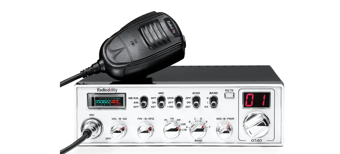
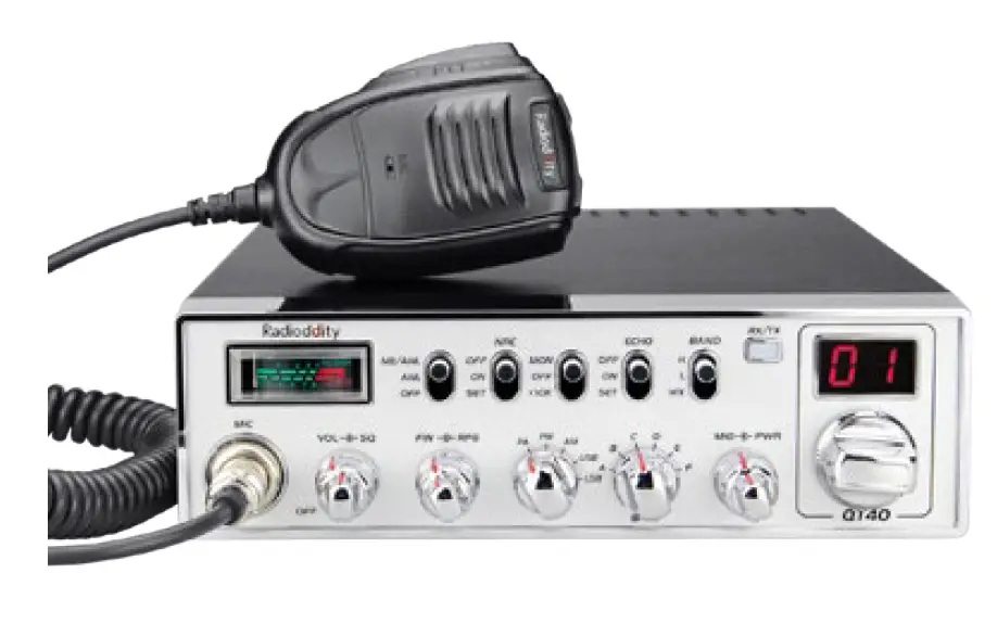
Radioddity QT40 10 Meter Amateur Radio
FUNCTIONS & FEATURES
- FM/AM/USB/LSB/PA modes
- Weather Channel with ALERT and FM receiver 140-170MHz
- CTCSS/DCS, with separate settings for TX and RX
- TX and RX Noise Reduction (NRC) PC Programmable Scrolling Frequency Display Function
- SQ, ASQ Function RF Gain Adjustment
- Microphone Gain Adjustment
- RF PWR Adjustment
- PWR/RX RSSI Signal Meter
- NB/ANL Function
- FM Repeater Offset Function (+/- 100kHz) +10kHz
- Function Beep Level Adjustment
- TOT Function HI-CUT Function
- Busy Channel Lock
- TX Audio Monitor
- LED Brightness Adjustment
- SWR Readout and High SWR Protection
- Voltage Protection
- VOX Function
- Programmable Roger Beep
- Echo Function
- NPC Function
- SCAN Function
STANDARD ACCESSORIES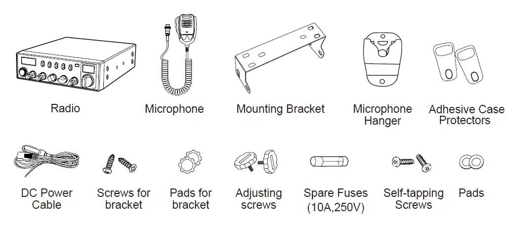
OPTIONAL ACCESSORIES
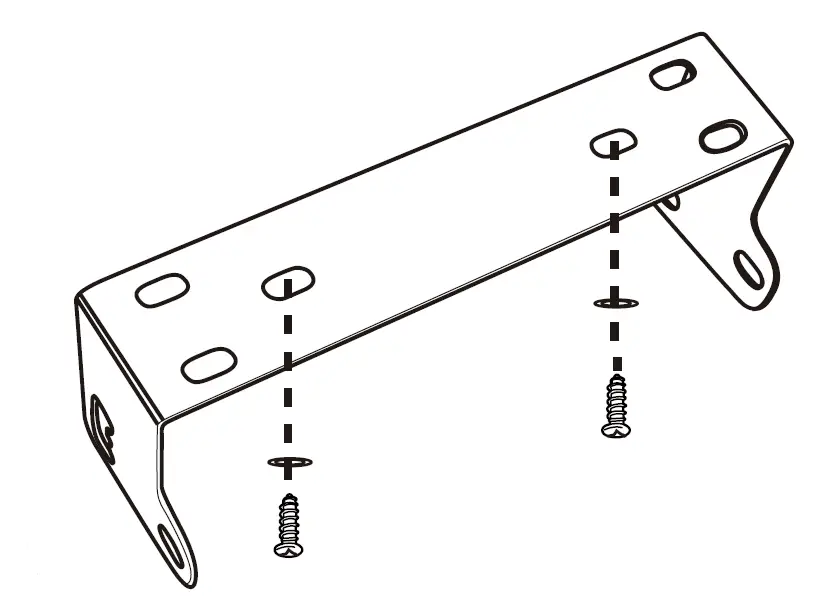
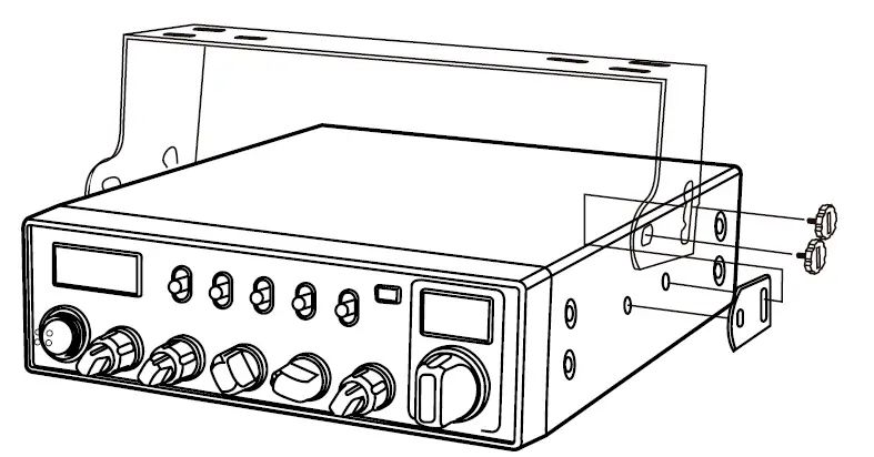
INSTALLATION
Choose the most appropriate location from a simple and practical point of view. If installed in a vehicle, care should be taken to ensure your radio does not obstruct the driver or passengers.
- Use the Self-tapping Screws and Pads to fix the Bracket to a suitable location.
- Attach the Adhesive Case Protectors to the inside ends of the Mounting Bracket and insert the Radio. Fit the Adjusting Screws loosely, and choose a suitable angle by moving the Adjusting Screws to one of the 3 positions on the Mounting Bracket.

- Tighten the Adjusting Screws firmly by hand. Make sure the radio and all accessories are securely mounted.

MICROPHONE CONNECTION
- Plug microphone connector into the microphone jack.
- Tighten the retaining ring on the microphone connector by hand.
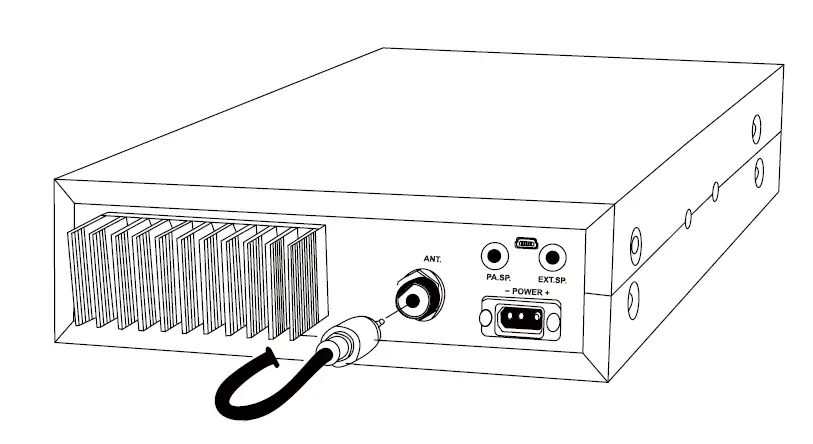
* ANTENNA INSTALLATION
Before using this radio, please install an efficient and resonant antenna. Using an antenna that is correctly installed and tuned will enable excellent communication performance.
This radio requires an antenna impedance of 50 ohms, unbalanced.
- Screw the antenna connector into the antenna jack.
- If required, grounding of the antenna system will ensure best performance.
 WARNING: ^ NEVER transmit without a connected resonant antenna, or a suitable 50 ohm load being connected. Damage to the radio may result. A To reduce the risk of electric shock, or radio damage, base station installations should include lightning protection devices. ^ Ask your Any tone dealer for available antenna options.
 - A mobile antenna can be mounted in various locations, for example:
 WARNING: ^ NEVER transmit without a connected resonant antenna, or a suitable 50 ohm load being connected. Damage to the radio may result. A To reduce the risk of electric shock, or radio damage, base station installations should include lightning protection devices. ^ Ask your Any tone dealer for available antenna options.
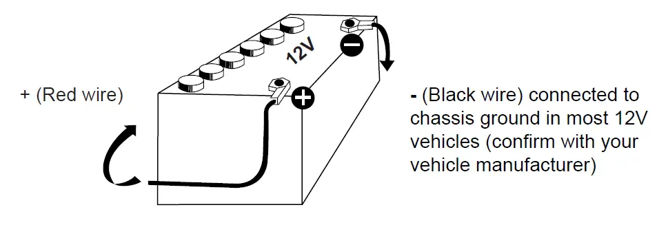
POWER CONNECTION
This radio requires a 13.8V (12V) DC power supply. Never connect the radio directly to a 24V DC battery system, as can be found in some vehicles. Please refer to the radio Specifications to ensure your 13.8V DC power supply can provide enough current (amps), otherwise poor performance may occur.
- Connect the positive (red) power cable to the + terminal of the battery.
- Connect the negative (black) power cable to the – terminal of the battery.
- Connect the DC power cable to the transceiver’s power supply connector.
- Locate the power cable away from high temperature, moisture, and other electrical systems. Ensure it is installed where it cannot be damaged.
- It is not recommended to use a vehicle cigar/cigarette lighter socket to power the radio, as it may not supply the correct voltage or current.
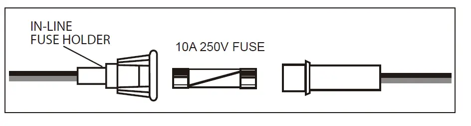
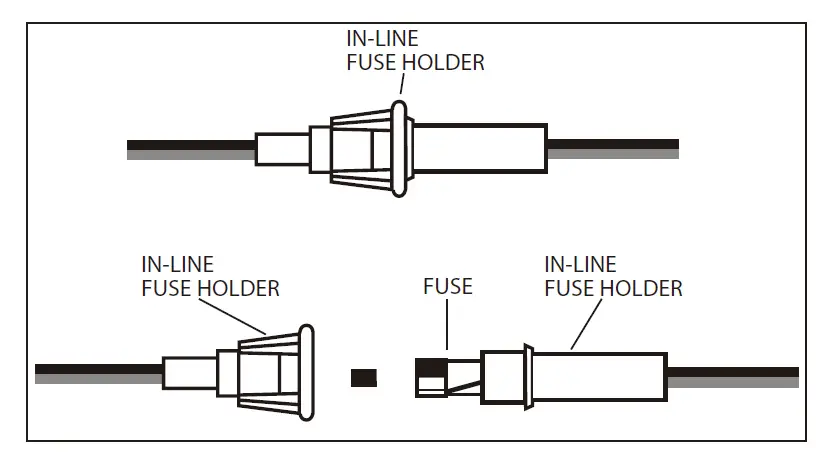
- Do not remove the fuse holder from the cable.
” REPLACING FUSES
This radio requires a 10A, 250V fuse. If the fuse blows, determine the reason, then correct the problem. After the problem is resolved, replace the fuse. If newly installed fuses continue to blow, disconnect the power cable contact your authorized dealer or an authorized service center.
- Twist the two fuse covers in opposite directions, and open it.

- Replace the blown fuse with new one, and close the fuse holder.
- Be sure to only use the correct fuse type, otherwise damage may occur.

INSTALL MICROPHONE HANGER
Choose a location which will not interfere with the driver. Use the supplied self-tapping screws and pads to install the hanger.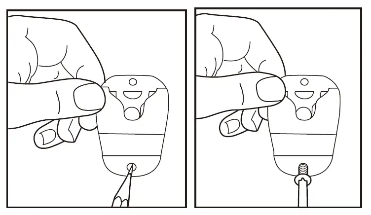 ” INSTALL EXTERNAL SPEAKER
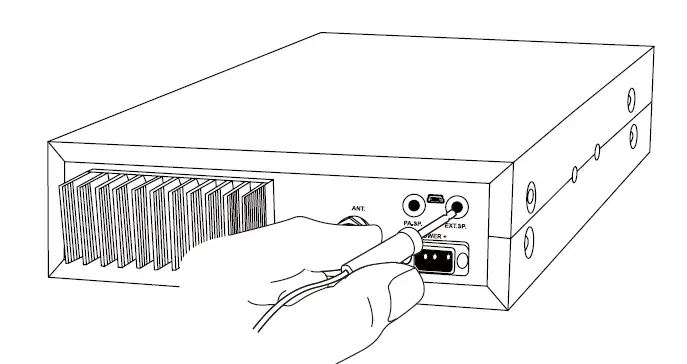
(Optional) If using an external speaker, please choose an 8 ohm speaker with a 3.5mm mono (double cable) TS type plug.
- Install the external speaker in a suitable place.
- Plug into the speaker jack.

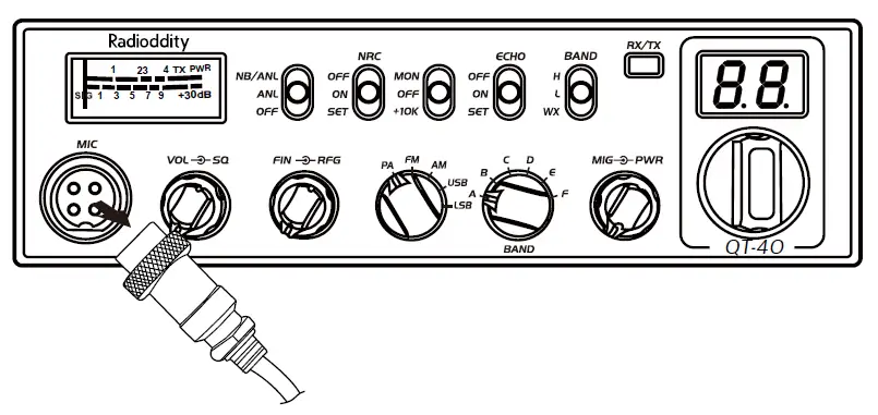
GETTING ACQUAINTED
Front Panel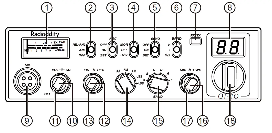
| No. | Functions |
| 1 | S-Meter |
| 2 | NB/ANL function on/off |
| 3 | NRC function on/off/set |
| 4 | Monitor/1OK on/off |
| 5 | ECHO function on/off/set |
| 6 | H Band, L Band or WX (FM RX) Band groups |
| 7 | TX/RX indicator |
| 8 | Channel Display: CH and Scrolling Frequency Display |
| 9 | Microphone connector |
| 10 | Power on/off and Volume level control |
| 11 | Squelch level control |
| 12 | FIN Frequency control: +/-500Hz and +/-5kHz |
| 13 | RF Gain control |
| 14 | MODE switch: PA/FM/AM/USB/LSB |
| 15 | BAND switch: A/B/C/D/E/F |
| 16 | Microphone Gain control |
| 17 | RF Power level control |
| 18 | Channel / Frequency control |
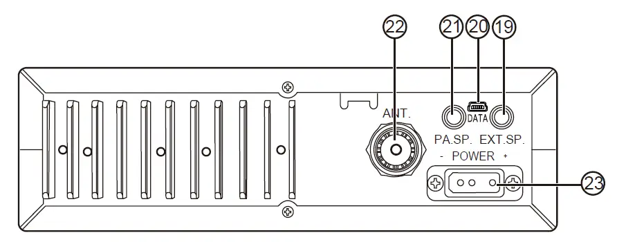
Rear Panel
| No. | Functions |
| 19 | External SP Jack |
| 20 | PC programming port |
| 21 | External PA Jack |
| 22 | Antenna Jack |
| 23 | Power Supply Jack |
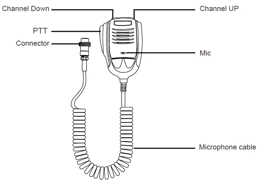
Microphone
HOW TO USE YOUR RADIO
Power OFF/ON
- Turn VOL clockwise to switch the radio ON, the radio may emit a beep (if the beep function is enabled). The LED display will show a channel number.
- Turn VOL anti-clockwise to switch the radio OFF.
- Volume Control
When the radio is turned on, turning VOL clockwise will increase the Volume level. Turning VOL anti-clockwise will reduce the Volume level.
Note: Adjust the Volume during communication to obtain a suitable level. Squelch Control When the radio is receiving, turn SQ control clockwise to adjust the Squelch level. - Mic Gain Control
When the radio is transmitting, turn MIG control to adjust the Microphone Gain. Turn the control clockwise to increase Mic Gain, and anti-clockwise to reduce Mic Gain. - RF Gain Control
When the radio is receiving, turn RF control to adjust the RF Gain. Turn the control clockwise to increase RF Gain, and anti-clockwise to reduce RF Gain. - RF POWER Control
Valid for AM/FM/LSB/USB modes. Turn PWR control to adjust the TX Output Power. Turn the control clockwise to increase Power, and anti-clockwise to reduce Power. # SCAN Function- With the radio in receive mode, press and hold the [UP] or [DN] key on the microphone for approximately 7 seconds until the SCAN feature starts. The dot “.” between the two channel digits on the LCD display flashes to indicate that the SCAN feature is active.
- Rotate the Channel switch or press either of the [UP/DNI keys on the microphone to change the SCAN direction.
- Short press [PTT] to exit SCAN mode.
Note: SCAN mode is available in all modes where the squelch is closed (audio muted), including WX/FM Receiver 140-170MHz mode.
- MODE Switch
Control Turn the mode switch to choose between PA/FM/AM/USB/LSB modes. - BAND Switch
Control Turn the band switch to select A/B/C/D/E/F band. - Channel / Frequency
Control Turn the channel control to select the desired channel. Turn the control clockwise to increase, and anti-clockwise to decrease. - Scrolling Frequency
- Display Hold the microphone [UP] and [DN] keys simultaneously, the LED display will show the working frequency. For example, 28.2050MHz will display as 28-20-50 repeatedly until the [UP] and [D] keys are released.
- Volume Control
SLIDE SWITCHES
| No. | Function | Position | Description |
|
1 |
NB/ANL | NB/ANL ANL OFF  | Turn on NB/ANL function |
| NB/ANL ANL OFF | Turn on ANL function | ||
| NB/ANL ANL OFF | Turn off NB/ANL function | ||
|
2 |
NRC | OFF ON SET | Turn off NRC function |
| OFF ON SET | Turn on NRC function | ||
| OFF ON SET | NRG level set: “rr” for RX noise reduction level, “tr” for TX noise reduction level. | ||
| 3 | MON + 10K | MON OFF +1OK | Turn on MON, 32 levels set by PC programming |
| MON OFF +1OK | No function (OFF) | ||
| MON OFF +1OK | Turn on +10KHz function | ||
| 4 | ECHO | OFF ON SET | Turn off ECHO function |
| OFF ON SET | Turn on ECHO function | ||
| OFF ON SET | ECHO Volume and Delay level set: “EL” for Volume level set, “Et” for Delay level set | ||
| 5 | BAND | H L WX | Choose higher frequency band group |
| H L WX | Choose lower frequency band group | ||
| H L WX | Turn on WX Channel and FM Receiver function 140-170MHz (set by PC prog ramming) |
FUNCTION MENU
- Press and hold the [UP] key of the microphone while powering the radio ON to enter into the radio function menu.
- Rotate the channel switch or press the [UP/DN] key of the microphone to select the menu function options.
- Press the [PTT] key of the microphone to enter into the menu setting.
- Rotate the channel switch to select the desired setting.
- Turn the radio OFF to save and exit the radio function menu.
| No. | Function | LCD Display | Description |
| 1 | BEEP | bp | Available setting: oF, 01-09 levels Default: oF |
| 2 | Roger Beep | rb | Available setting: oF, 01-05 levels Default: oF |
| 3 | WX alarm | AL | Available setting: oF, on Default: on |
| 4 | Dimmer | dI | Available setting:1-3 Default: 3 |
| 5 | NPC | nP | Available setting: oF, on. Default: oF (NPC on is valid for AM/SSB modes only. Only use with LOW TX Power. Adjust MIG to control peak TX Power) |
| 6 | VOX level | uL
| Available setting: oF, 01-09 levels Default: oF |
| 7 | VOX delay | u
| Available setting: 01-09 levels Default: 3 |
| 8 | Scan type | 5n | Available setting: ti (time scan), Sq (squelch scan) Default: Sq |
| 9 | Microphone type | n | Available setting: EL (condenser), dy (dynamic) Default: EL |
| 10 | Fine freq adjust | Fn
| oF: turn off frequency fine adjustment. r: turn on fine adjustment for RX frequency only t: turn on fine adjustment for TX frequency only rt: turn on fine adjustment for both TX/RX frequency Default: rt |
| 11 | Fine freq range | F | F1: FIN control adjustment range +/- 500Hz F2: FIN control adjustment range +/- 5kHz Default: F2 |
| 12 | SWR display | 5r | on: turn on SWR display oF: turn off SWR display Default: on |
| 13 | Reset | r | ALL: Move NB/ANL slide switch to OFF, press PTT to reset ALL radio data to factory default CHANNEL: Move NB/ANL slide switch to NB/ANL, press PTT to reset CHANNEL data to factory default |
ERROR CODE
The radio is equipped with multiple protection functions. If an error occurs, the RX/ TX indicator light will illuminate yellow, and the LED display will show the applicable error code:
- E1: Voltage too low
- E2: Voltage too high
- E3: WX function invalid
- E4: Current BAND invalid
- E5: TX SWR too high
SPECIFICATIONS
| GENERAL | |
| Frequency Range | 28.000-29.695MHz (PC Programmable) |
| Frequency Band | L / H band: A/B/C/D/E/F. WX/VHF RX: 140-170MHz |
| Channels | 480 channels (40 programmable per band) |
| Frequency Control | Phase-Locked-Loop Synthesizer |
| Frequency Tolerance | ± 5.0 ppm |
| Temperature Range | -20°c to +50°c |
| Microphone | With push-to-talk [UP]/[DN] buttons and coiled cord |
| Input Voltage | 13.8V |
| Dimensions (in mm) | 287(L)x200(W)x61(H) |
| Weight | 1.5kg |
| Antenna Connector | UHF, S0239 |
| TRANSMITTER | |
| Power Output | AM:1-12W(adjustable) FM:1-40W(adjustable) USB/LSB:1-35W(adjustable) |
| Current Drain | 8A(with modulation) |
| Modulation | FM/AM/SSB |
| Inter-modulation Distortion | SSB: 3rd order, more than -25dB; 5th order, more than -35dB |
| SSB Carrier Suppression | 55dB |
| Unwanted Sideband | 50dB |
| Frequency Response | AM/FM: 450 to 2500Hz |
| Output Impedance | 50 ohms, unbalanced |
| RECEIVER | |
| Sensitivity | AM:1.0µV for 10dB(S+N)/N at greater than 1/2watt of audio output. FM: 1.0µV for 20dB (S+N)/N at greater than 1/2 watt of audio output. SSB: 0.25µV for 10dB(S+N)/N at greater than 1/2- watt of audio output. |
| Selectivity | AM/FM:6dB@3kHz,50dB @9kHz SSB: 6 [email protected],60dB @3.3kHz |
| Adjacent-Channel Selectivity | 60dB AM/FM & 70dB SSB |
| Image Rejection | More than 65dB |
| IF Frequency | AM/FM: 10.695MHz 1st IF, 455kHz 2nd IF SSB: 10.695MHz |
| RF Gain Control | 45dB adjustable |
| Automatic Gain Control (AGC) | Less than 10dB change in audio output for inputs from 10µV to 100,000µV |
| Squelch | Adjustable; threshold less than 0.5µV. Automatic Squelch Control (only AM/FM) 0.5µV |
| ANL | Switchable |
| Noise Blanker | RF type, effective on AM/FM and SSB |
| Audio Output Power | 3 watts into 8 ohms |
| Frequency Response | AM/FM: 300 to 2800Hz |
| Built-in Speaker | 8 ohms, round |
| External Speaker (Not Supplied) | 8 ohms, disables internal speaker when connected |
Note: Specifications are subject to change without notice due to advancements in technology.


