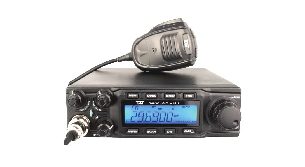
![]() PR8109 HAM-MobileCom 1011 CB Radio
PR8109 HAM-MobileCom 1011 CB Radio
Instruction Manual
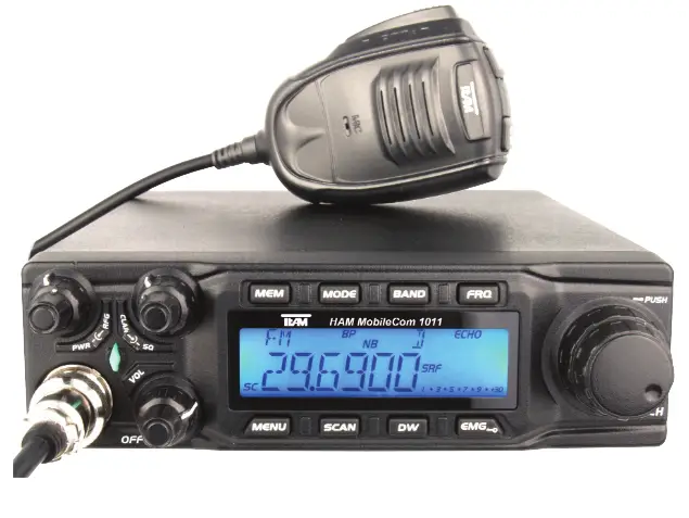
PR8109 HAM-MobileCom 1011 CB Radio
With the TEAM HAM MobileCom 1011, you purchased a quality amateur mobile radio, designed to fulfill the highest demands of radio communication.
The performance and the qualitiy of the HAM MobileCom 1011, which contains the newest technologies, will satisfy you.
Please read this instruction manual carefully before operating the HAM MobileCom 1011 for the first time. You will learn about the proper setup, the different features and functions of your new mobile radio.
The HAM MobileCom 1011 is an amateur mobile radio and, therefore, can only be operated by a licenced amatuer radio operator. The amateur radio operator is responsible to comply with the license provisions.
PRECAUTIONS
Please follow the instructions to avoid fire, injuries and damage of the transceiver.
It is recommended, as a general guideline, not to exceed the suggested times for transmission (1 minute) and reception (4 minutes). These operations generate heat. Too much heat may cause damage.
Please do not disassemble or assemble the transceiver under any circumstances.
Please do not expose the transceiver to direct sunlight; do not place the transceiver near any heating devices, either.
Please do not put the transceiver in extremely dusty or moist places and do not place it on unstable, uneven surfaces.
If the transceiver emits smoke or strange odor, turn it off, disconnect it from the power source and immediately contact your authorized, local TEAM Electronic dealer.
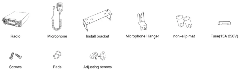
CONTENTS
Unpack the transceiver set carefully. We recommend that you identify the listed items before discarding the packing material.
If any items are missing or have been damaged during shipment, please contact the dealer immediately.
OVERVIEW FUNCTIONS
| 1. Big LCD display; channel no. / frequency and various functions | 15. +10KHZ Function |
| 2. AM / FM / USB / LSB mode | 16. SWR, S/RF function |
| 3. Frequency Tuning Step can be 10HZ, 100HZ, 100Khz,1MHz | 17. TOT function |
| 4. ± 1.5KHz Clarifier | 18. HI-CUT Function |
| 5. Menu functions PC programming software | 19. EMG CALL, priority channels |
| 6. ECHO Function | 20. SWR PROTECTION |
| 7. SQ, ASQ Function (FM and AM mode only) | 21. Power Supply Voltage Protection |
| 8. RF GAIN Adjustment | 22. Key-Lock Function |
| 9. RF PWR Adjustment | 23. 7 LCD colors |
| 10. SCAN Function | 24. 10 memory banks with 40 channels each (programmable via software) |
| 11. Programmable RB Function | 27. PC programming with optional software |
| 12. NB/ANL Function | 25. DTMF Sub Code Function |
| 13. DW DUAL-WATCH Function | 26. CTCSS / DCS Sub Code Function |
| 14. BEEP Voice Prompt |
SETUP
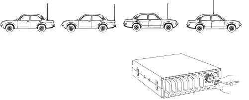
Base the decision about the position of the HAM MobileCom 1011 in your vehicle on the aspect of safety. No part of the setup, i.e. radio, microphone, cable, etc., should restrict or obstruct the driver or passenger in any way.
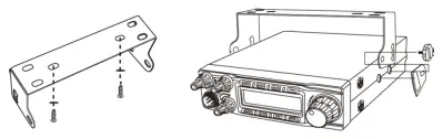
U-bracket holder
- Mount the U-shaped bracket holder with the threading screws and the washers at the desired location in the driver cabin.
- Mount the radio onto the bracket holder with 2 adjusting screws and rubber pads in the rear holes of the bracket holder.

- Set the desired angle of the radio at the bracket holder and fix the angle with the remaining adjusting screws and rubber pads.
microphone holder
- Mount the microphone holder with the two threading screws onto the desired location in the vehicle.
- Plug in the 6-pin microphone connector into the front jack (16), located on the left side of radio. Tighten the retaining screw of the microphone plug.
antenna
The antenna should be matched with the radio, otherwise a part of the transmit power will be reflected in the antenna and will not be radiated. This will reduce the range of operation. Since the antenna is one of the most important links in the setup, the following criterias are very important.
General :
- The frequency range of the antenna has to cover the programmed frequencies on the radio.
- The position of the antenna should be as elevated and unobstructed as possible.
- Ensure that the cable and the connector of the antenna are intact and that the plug is connected properly.
- Ensure that the cable is not bend too much.
- The length of the antenna rod and the range of operation are related. The longer the rod, the further the distance.
Upon antenna-mounting, the following has to be considered :
- The antenna should be placed in the middle of a vehicle part.
- The antenna base should have good contact to a metal, conductive surface of the vehicle.
Beside the fixed mounting of antennas, which requires drilling of the body, antennas can also be set up via a magnetic mount.
- To avoid interferences with radio and TV reception, place the antenna as far away as possible from these sources of interferences.
- All connected cables should not exceed the maximum length of 3 meters.
For a good grounding of the antenna, we recommend one of these placements:
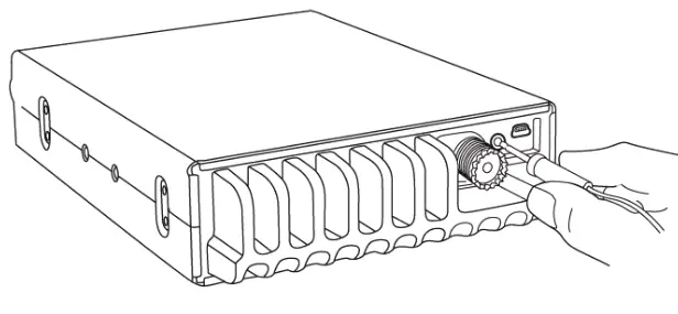
antenna connection
Connect the antenna connector of the cable with the PL-jack (20), located on the rear of the radio. Ensure a proper connection of the cable to the antenna base. Improper connections can cause damages to the radio and a reduction of the operational range may be the result.
The antenna setup has to be adjusted to the radio. Otherwise, a part of the transmission power is reflected at the antenna and is not radiated. A reduced range of operation could be the consequence.
power supply connection
The voltage has to be 13.8 V DC with negative grounding. Ensure that the positive and (+, red) and negative (-, black) polarity is correct, bevor you connect the radio. The connection of the radio to the power supply, has to be set up by an authorized technician.
Connect the power cable directly onto the batterie. Do not use a cigarette lighter adapter because this kind of connectivity might not provide enough currenct for a proper operation of the radio. Pay Special attention to the correct polarity, when connecting the cable onto the batterie.
CAUTION
- Please ensure proper polarity
- Please check the fuse before first use of the radio. Missed or defect fuses need to be re placed before operation of the radio.
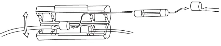
fuse replacement
This radio requires a 15A/250V fuse. If the fuse blows, determine the cause, then correct the problem. After the problem is resolved, replace the fuse. If newly installed fuses continue to blow, disconnect the power cable and contact your authorized dealer or an authorized service center.
- Pull the two fuse cover in difference direction and open it.
- Replace the broke fuse with good one, and close the fuse holder.
- Be sure to use suggested fuse, or it might damage the radio.
INSTALL EXTERNAL SPEAKER
If you want to use an external speaker, please choose an 8 ohm speaker with 3.5 mm mono band plug.
Position the external speaker in a safe location, where it cannot obstruct the driver or a passenger and plug the connector into the speaker jack (19), located on the rear of the radio.
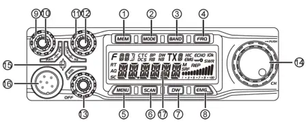
REAR PANEL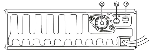 ELEMENTS front
| No. | Key | Functions |
| 1 | MEM | Use, store or delete memory channel |
| 2 | MODE | Switch mode: FM, AM, USB, LSB |
| 3 | BAND | Switch band: A-J |
| 4 | FRQ | Switch between channel mode and frequency mode |
| 5 | MENU | Function Menu key |
| 6 | SCAN | Scan, Scan add, Scan delete |
| 7 | DW | Dual-watch scan, Dual-watch setup |
| 8 | EMG | Energy Channel; Keypad lock. |
| 9 | PWR | RF Power Control |
| 10 | RFG | RF Gain Control |
| 11 | SQ | Squelch Control |
| 12 | CLA | SSB Clarifier switch |
| 13 | VOL/OFF | Power On/Off; Volume Control. |
| 14 | CH | Channel Switch, Push key. |
| 15 | RX/TX Indicator | |
| 16 | Microphone Jack | |
| 17 | LCD Display |
| 18 | PC Cable Jack |
| 19 | External Speaker Jack |
| 20 | Antenna Jack |
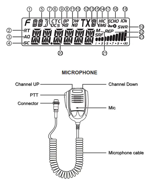
LCD
| 1 | Appears when press MENU key. | |
| 2 | RT | Appears when adjust SSB clarifier frequency. |
| 3 | AO | Appears when use ASQ. |
| 4 | SC | Appears during scan function. |
| 5 | Indication of working mode. | |
| 6 | CTC | Appears when set with CTCSS code. |
| 7 | DCS | Appears when set with DCS code. |
| 8 | BP | Appears when Beep voice is ON. |
| 9 | RB | Appears when RB function is ON. |
| 10 | DW | Appears when Dual-watch function is ON. |
| 11 | NB | Appears when adjust Noise Blanker is ON. |
| 12 | TX | Appears during transmiting. |
| 13 | Indiation of working band. | |
| 14 | H/C | Appears when Hi-cut function is ON. |
| 15 | EMG | Appears when using Emergency channel. |
| 16 | ECHO | Appears when Echo function is ON. |
| 17 | iwO | Appears when the Keypad lock function is ON. |
| 18 | 10k | Appears when +10Khz function is ON. |
| 19 | SWR | Indication of SWR level. |
| 20 | Display of frequency and channel. | |
| 21 | M | Appears when using memory channels |
| 22 | REP | Appears when repeater function is ON. |
| 23 |  | Display of TX/RX Signal strength. |
OPERATION
On/Off
- To switch on the HAM MobileCom 1011, turn the volume control (13) clockwise, over the contact barrier. An acoustic signal is emitted and the LCD lights up.
- To switch off the radio, turn the volume control (13) counterclockwise over the contact barrier.
Volume
Turning the volume control (13) will adjust the volume level. The LCD will then display the actual volume level (1-36).
TX Power
For the adjustment of the tx power use the power control (9). The maximum tx power of the selected frequency band (AM / FM / SSB) is set by turning the power control clockwise all the way to the end.
RF Gain
For the adjustment of the receiver sensitivity use the RF-Gain control (10). If received signals are distorted due to immediate proximity to the transmitter, the receiver sensitivity can be reduced with the RF Gain function.
SQUELCH
For the adjustment of the squelch level use the squelch control (11). During adjustment, the symbol SQ and the actual level (1-36) are displayed.
SSB Clarifier
For fine tuning of the transmitter and receiver frequencies for USB / LSB, use the SSB Clarifier control (12).
Channel Selection
Use the rotary channel selector control (14) for channel selection.
Please note: for a manual entry of the frequency, push the rotary channel selector [PUSH] (14). The fourth digit starts blinking. Set the value by turning the channel selector and push it to confirm the entry and to proceed to the next digit. Continue repeating these steps until all entries have been made.
FUNCTION KEYS
[MEM]
MEMORY CHANNELS M1-M6:
To enter or quit the memory channel mode, press the key【MEM】(1). The letter M (21) to the right of the frequency or the memory channel number indicates the active status of the memory channel mode.
In channel mode the display reads ME–M(1-6). In frequency mode, the frequency of the selected memory channel is displayed. Use the key【FRQ】(4) to switch between the channel mode and the frequency mode. The selected frequency band (A-I) is shown on the top of the LCD (13).
save a memory channel:
To save a channel as a memory channel, exit memory channel mode first.
Then, select the frequency and hold the key【MEM】until the memory channel mode is activated. The letter M and ME-M(1-6), with M(1-6) blinking, will appear.
Now, select the memory channel number where the frequency should be saved and hold the key【MEM】until M(1-6) stops blinking.
[MODE]
To switch between the operating modes FM-AM-USB-LSB, press the control【MODE】(2). The actual operating mode is shown in the upper left LCD (5).
[BAND]
To switch between the frequency bands A-B-C-D-E-F-G-H-I-J, press the control【BAND】(3). The actual frequency band is shown in the upper left LCD (13).
[FRQ]
Use the control【FRQ】(4) to switch between frequency and channel mode.
[MENU]
All functions and settings of the HAM MobileCom 1011 are organized in three different menus.
The menus channel settings (PD, HICUT, NB, ECHO, +10kHz, ROGER, BUSY, SCAN) and general settings (BEEP, INDIC, MIC, NOG, TOT, TSR, TDC, SCAN, FIN, COLOR, RESET) are activated with the control [MENU] (5).
To open the menu channel settings, press the key【MENU】(5) shortly. The symbol F (1) appears in the upper left corner of the LCD. Press the channel selector [PUSH] (14) to open the menu.
To open the menu general settings, press the key【MENU】(5) approximately 2 seconds.
Once the menu is activated, use the rotary channel selector (14) to select a function. To edit the setting for the selected function, press the channel selector [PUSH] (14). Make your selection by turning the rotary channel selector and press it to confirm your selection. To exit the menu press any key.
[SCAN] channel scanning
- Start channel scanning by pressing the key【SCAN】(6). The symbol SC (4), located in the lower left corner, starts blinking.
- Change the direction of the scanning (Up / Down) by turning the rotary channel selector.
- To stop the channel scanning press the key【SCAN】(6) again.
add to/delete from scan list
In channel mode, only the channels of the scan list will be scanned. Channels that are added to the scan list can be recognized by the letter SC (4) in the lower, left corner. To add a channel to the scan list (or delete it), hold the key 【SCAN】(6) for approximately 2 seconds. The scan list can also be edited via the menu channel settings.
[DW] Dual-Watch On/Off
Pressing shortly the key【DW】(7), will activate the dual watch function. Once activated, the symbol DW (10) appears.
Setup Dual Watch function
- Select the first channel for the dual watch function.
- Hold the key【DW】(10) for appr. 2 seconds until the symbol DW starts blinking.
- Now, set the second channel for the dual watch function and press again the key【DW】(10) for confirmation.
[EMG]
priority channels 9/19 and key lock priority channel 9/19: The tri-state key【EMG】(15) switches from priority channel 9 to priority channel 19 and then back to regular mode. The priority channels 9 and 19 are indicated by the symbol EMG (15).
key lock: To activate the key lock function, which deactivates all keys except for the PTT key, hold the key【EMG】(15) for approximately 2 seconds until the key symbol (17) appears.
- To open the menu channel settings, first, press the key【MENU】(5) shortly (the symbol F (1) will appear) and then, press the channel selector【PUSH】(14).
- Make your selection by turning the rotary channel selector (14).
- Press the channel selector【PUSH】(14) to access the available settings.
- Now, make your selection by turning the rotary channel selector (14) and confirm your selection by pressing the channel selector【PUSH】(14).
- To exit the menu, press the key【MENU】(5) or any other key.
| No. Function | LCD S mbol | settings and description |
| 1 BUSY | transmission blockage on occupied channels; ON/OFF | |
| 2 REP | direction of TX REP frequency shift OFF : no shift REP+ : shift to top REP- : shift to bottom | |
| 3 CTCSS/DCS | TSQ | CTCSS: 67.0-250.3Hz, Total 38 groups; DCS: D023N—D754N, Total 104 groups; OFF: Shut CTCSS/DCS codefunction. Default: OFF |
| 4 SCAN | SC | edit scan list; symbol SC (14) ADD / DEL |
| 5 Public Data | PD | General settings; ON / OFF; activates / deactivates Menu Channel settings in active state, these functions are not available: HICUT, NB, ECHO, 10KHZ and ROGER |
| 6 HI-CUT | HIC | receiving tone type; ON / OFF |
| 7 NB | NB | Noise Blanker; ON / OFF |
| 8 ECHO | ECHO | Echo; ON / OFF |
- Press and hold the key【PUSH】(14) for appr. 2 seconds to open the menu.
- Turn the rotary channel selector (14) to make your selection.
- Push the key【PUSH】(14) to access the available settings for the function.
- Turn the rotary channel selector (14) to make your selection.
- Confirm the selection by pressing the key【PUSH】(14).
- Press any key to exit the menu.
| No. | Function | LCD Symbol | settings and description |
| 1 | Hi-cut | HIC | receipt tone type; ON / OFF |
| 2 | NB | NB | Noise Blanker; ON / OFF |
| 3 | Echo | ECHO | Echo; ON / OFF |
| 4 | 10kHz | 10k | frequency shift +10 kHz; ON / OFF |
| 5 | Roger | RB | Roger Beep; 1-8, OFF |
| 6 | DTMF PTT ID | DMTF | BOT: Press PTT to send DTMF 6 EOT: Release PTT to send DTMF encode; CALL: Hold PTT+EMG to send DTMF encode; Note: If the M1-M16 storage has no PTT ID, DTMF function is defaulted OFF. Users are able to choose the DTMF group only when programmed with code. |
- Push and hold the key【MENU】(5) for appr. 2 seconds to open the menu.
- Turn the rotary channel selector (14) to make your selection.
- Push the key【PUSH】(14) to access the available settings for the function.
- Turn the rotary channel selector (14) to make your selection.
- Confirm the selection by pressing the key【PUSH】(14).
- Press any key to exit the menu.
| No. | Function | LCD Symbol | settings and description |
| 1 | BEEP | BP | beep tone; confirms any entry; ON / OFF |
| 2 | INDIC | OFF : transmit frequency during transmission SWR : SWR during transmission TOT : remaining TOT time during transmission DC : indicates voltage during transmission | |
| 3 | MIC | microphone sensitivity; 1-36 | |
| 4 | NOG | monitor sensitivity; 1-32, OFF | |
| 5 | TOT | transmit time limiter; OFF, 30-600s in 30-seconds-steps | |
| 6 | TSR | SWR protection, protects the radio if SWR is out of limit; ON / OFF limit has to be programmed via software | |
| 7 | TDC | Voltage protection, protects the radio if voltage is out of limits; ON / OFF min. and max. limits, to be programmed via software | |
| 8 | SCM | channel scan types, SQ : signal / TI : time | |
| 9 | FIN | frequency fine-tuning OFF R : reception frequency fine-tuning T : transmission frequency fine-tuning RT : reception and transmission fine-tuning | |
| 10 | COLOR | LCD color; WHITE, BLUE, GREEN, YELLOW, RED, PURPLE, CYAN | |
| 11 | TX REP | for repeater operation, tx frequency shift; range: 100Hz – 5MHz | |
| 12 | FR–CH | settings: CHAN / FREQ | |
| 13 | ASQ | automatic squelch, preset in the range 1-9, Default: 05 | |
| 14 | DTMF | S TIME: DTMF transmit time / FDELAY: First digital time C TIME: Pre-carrier time / *# TIME: * and # delay time D CODE: code setting time / TX DIS: Display setting for DTMF transmit MEM: DTMF encode storage list; Note: In the DTMF encode storage list (M1-M16), press PUSH to edit DTMF code, then turn channel knob to choose desired value, press PUSH again to edit next list, after finish setting, hold PUSH to store it and back to main menu. Reset to factory settings | |
| 15 | RESET | OPT : all settings and functions / ALL : all frequencies, settings & functions |
SPECIFICATIONS
GENERAL
| Frequency Range | 28.000-29.690 MHz (programmable) |
| Frequency Band | A/B/C/D/E/F/G/H/I/J |
| Channel | 40 channels (programmable) in each band |
| Frequency Control | Phase-Locked-Loop Synthesizer |
| Frequency Step | 100Hz / 1KHz / 10KHz / 100KHz / 1MHz |
| Frequency Tolerance | 0.01% |
| Frequency Stability | 0.00% |
| Temperature Range | -20℃to +50℃ |
| Microphone | with push-to-talk /UP/DN and coiled cord |
| Input Voltage | 13.8V |
| Dimensions (in mm) | 245mm (W) x 157mm (D) x 48mm (H) |
| Weight | 1.46kg |
| Antenna Connector | UHF, SO239 |
TRANSMITTER
| Power Output | AM: 12W / FM:30W / SSB: 60W (PEP) |
| Drain | 12A (with modulation) |
| Modulation | FM/AM/USB/LSB |
| Inter-modulation Distortion | SSB: 3rd order, more than -25dB; 5th order, more than -35dB |
| SSB Carrier Suppression | 55dB |
| Unwanted Sideband | 50dB |
| Frequency Response | AM/FM: 300 to 3000Hz / SSB: 450 to 2500Hz |
| Output Impedance | 50 Ohms, unbalanced |
![]() HAM MobileCom 1011
HAM MobileCom 1011
for sale and use in: Cyprus
TEAM Electronic GmbH
Bolongarostrasse 88
D-65929 Frankfurt am Main
GERMANY
Tel. ++49 – 69 – 300 9 500
Fax ++49 – 69 – 314382
eMail [email protected]
Web Page www.team-electronic.de
V4 02/2021


