
 resolutions ZULU-2-Telemetry Smart Radio Telemetry Module
  Features
- Small Form Factor
- 2 Analogue I/O (10bit)
- Data Reception LED
- Secure Data Protocol
- Easy Pairing Process
- On-Board XTAL
- One to One operation
- M100mW Transmit Power
- 10 Digital Input / Outputs
Range up to 2,000 Metres - Minimal external components
- 868MHz Operating Frequency
- 10 Channel Transceiver Module
- 90-100KHz PWM
- CE Compliant, Licence Free Use
- Ultra-Low Voltage 2.4—3.6V
Applications
- Remote Control
- Remote Networking
- Remote Switching
- Remote Traffic Lights
Description
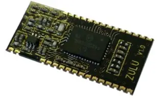
The ZULU2 Telemetry Module provides a reliable Transceiver based industrial Remote Switch with up to 2,000 metres range. Two modules are combined to provide a simple network of radio switching. Each unit is supplied ready to operate, once paired with another Module a remote control system is created. Connections for Power, antenna and Input / Output are the only connections required.
Ordering Information
| Part No | Description |
| ZULU2-T868-SO | Radio Telemetry Module SMT Package |
Pinout
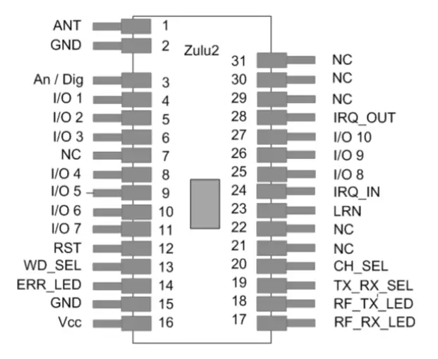
Pin Description
| Pin No | Name | Direction | Description |
| 1 | ANT | In | Antenna Input / Output 50ohm Impedance |
| 2, 15 | GND | In | Connect to ground |
| 3 | Analogue / Digital | In | Connect to Vcc = I/O1-2 are digital Connect to GND = I/O1-2 are Analogue |
| 4 – 5 | I/O1-2 | In / Out | Analogue or digital I/Os 0—Vcc, connect to GND if unused |
| 6, 8-11, 25 -27 | I/O 3-10 | In / Out | When configured as transmitter: Digital inputs: high Impedance inputs When configured as receiver: Digital outputs: LVCMOS output drive |
| 7, 21-22 | NC | Leave unconnected | |
| 12 | Reset | In | Resets module operation, pull high for ordinary use. |
| 13 | Watchdog | In | Connect to Vcc = Turns OFF “watchdog” Connect to GND = Turns ON “watchdog” |
| 14 | Error LED | Out | LED drive output. Flashes if ZULU2 TX has not received acknowledgement or ZULU2 RX has not received watchdog. |
| 16 | Vcc | In | Supply voltage |
| 17, 18 | TX/RX LEDs | Out | Active LED output when the module is transmitting or receiving RF data packets. |
| 19 | TX/RX | In | Connect to Vcc = Module is a Transmitter Connect to GND = Module is a Receiver |
| 20 | Ch Sel | In | Sets the channel frequency Connect to Vcc = Operates on ch A 869.500 Connect to GND = Operates on ch B 868.133 |
| 23 | Learn | In | Connect to momentary switch to GND, when activated places the module into pairing mode. |
| 24, 28 | IRQ In/Out | In / Out | Connect together to enable RF interrupts on chip (mandatory). |
| 29-30 | XTAL1-2 | In | These pins are provided as legacy to ensure compatibility with older ZULU modules |
| 31 | NC | Leave unconnected |
General Description of Operation
Each module can be set to act as a ‘ Transmitter’ or ‘Receiver’ A remote telemetry system is achieved when two modules are paired together, as transmitter (ZULU2 TX) and receiver (ZULU2 RX).
Each time an input changes on the ZULU2 TX, it will transmit the status of its inputs to the paired ZULU2 RX(s). which will set its outputs to follow the ZULU2 TX Inputs and reply back with an acknowledge signal. Once completed the modules will then go into sleep mode.
Pin Descriptions
Channel Select (pin 20)
This sets the operating carrier frequency of the module. This enables separate groups of mod-ules to coexist in the same vicinity without any interference. For operation see page 2.
TX / RX (pin 19)
When connected to Vcc ZULU2 is a Transmitter.
When connected to GND ZULU2 is a Receiver.
XTAL1, XTAL2 (pins 29, 30)
The ZULU2 module no longer requires a 30MHz drive crystal to be connected between XTAL1-2. See notes on page 2 for compatibility with older versions.
Learn / Erase (pin 23)
Each transmitter has a unique identity. A receiver can ‘sync’ with a transmitter so that the receiver outputs will respond to the transmitter inputs.
- To Learn
- Briefly press the “sync” switch on the receiver
- Briefly operate any of the transmitter inputs
- To Erase
- Hold pin 7 on the receiver to ground for >10seconds.
- (For completed circuit press learn switch for 10sec)
- Indication of the process is shown the TX/RX LED.
Tx / Rx LEDs (pins 17, 18)
Direct LED drive which operate whenever there is RF activity Tx or Rx.
| Mode | TX/Rx LED | Description |
| Normal operation | ON | Module is transmitting/receiving RF data |
| OFF | No RF data is being transmitted/received | |
| Learn mode | Flashing at low speed | The module is searching for another to pair with. |
| Flashing at high-speed 3secs | Pairing successful |
The following descriptions apply to the ZULU Module in TRANSMITTER Mode
When configured as a Transmitter the ZULU2 Module will automatically default to low power sleep mode until any input state change takes place.
On receipt of an input state change the ZULU2 TX will transmit a packet showing the status of all inputs (multiple state changes can take place simultaneously).
The ZULU2 TX will remain “awake” until:
- The paired ZULU2 RX Module has acknowledged, or
- A timeout value of 4 retry transmissions. (Pin 14 output will then be flashed)
- Analogue / Digital (pin 3)
This input configures Input 1-2 to be analogue or Digital inputs.
Note: this input is read at power up only. - Analogue Inputs (4,5)
If enabled each input is 10bit A/D which can accept a voltage between 0 –Vcc.
Each input is sampled ten times per second, and the value is averaged before transmission. ZULU2 TX will transmit whenever there is a change in the detected input voltage of 0.025V.
If no change of voltage is measured then the ZULU2 TX will not transmit. A nominal 1uF capacitor is recommended across the analogue inputs in order to prevent noise being read and transmitted.
Note: A maximum of three RF packets are sent per second. - Digital Inputs
High Impedance Inputs, LVCMOS / LVTTL compatible.
Can be connected directly to CMOS/TTL logic or switch inputs connected to 0V (active low)
A change on the input will cause the ZULU2 TX to wake, read the inputs and initiate RF transmission. - Watchdog Input (pin 13)
The watchdog is designed to enable the ZULU2 RX to be aware of any potential problems with the RF link to a sync’ed ZULU2 TX.
When activated the ZULU2 TX will automatically transmit a call in packet a regular basis every 10seconds. Input statuses are not sent as part of the watchdog signal.
Note: This pin is only read on power up. Watchdog is only valid on a 1-1 system. - RF Fault (pin 14) Direct drive to LED. Each time the ZULU2 TX transmits the status of its inputs, it expects an acknowledgement from the paired receiver. If this is received then the RF Fault LED is not used. If no acknowledgement is received RF Fault is flashed.
| RF Fault LED Status | Description |
| OFF | Receiver has acknowledged correctly |
| Flashing at 1Hz | No acknowledgment received |
Transmitter example application circuit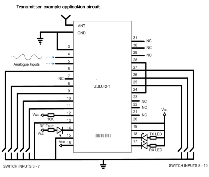
Notes
Watchdog is ON Channel selected is 869.500 Analogue inputs active
The following descriptions apply to the ZULU2 module in RECEIVER mode
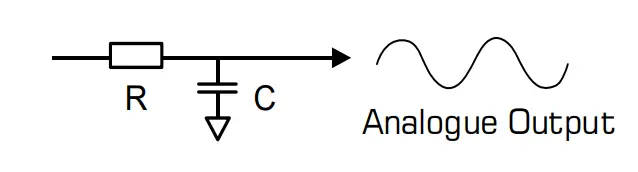
Analogue outputs (pin 4, 5)
- If enabled the ZULU2 RX outputs PWM signal.
- The PWM may be used directly (e.g. for motor control).
- The PWM signal is a proportional digital output representing the analogue input.
- If the analogue input is 0V then the PWM output will be ‘0’.
- If the analogue input is 1/2Vcc then the PWM output will be a square wave with 50% duty cycle, (operating at approx 90-100KHz).
- If the analogue input is Vcc then the PWM output will be ’1’.
- In order to re-create an analogue signal (representing the analogue input at the transmitter), the output should be fed through an RC network as above.

- Digital outputs
CMOS / TTL compatible outputs. Can be connected directly to CMOS/TTL logic or drive. - Analogue / Digital (pin 3)
This input configures outputs 1-2 to be analogue or digital outputs.
Note: this input is read at power-up only. - Watchdog Input (pin 13)
When activated the ZULU2 RX module will automatically expect to receive a watchdog signal from the ZULU2 TX on a regular basis (10seconds). If it has failed to receive this within a 30second period it will assert drop all outputs and flash the RF fault output. - RF fault
Direct drive to LED. Flashes when watchdog fails.
| RF fault status | Description |
| OFF | ZULU2 RX has received watchdog correctly |
| Flashing at 2Hz | No watchdog received |
| OFF | watchdog is inactive |
Receiver Application Circuit 
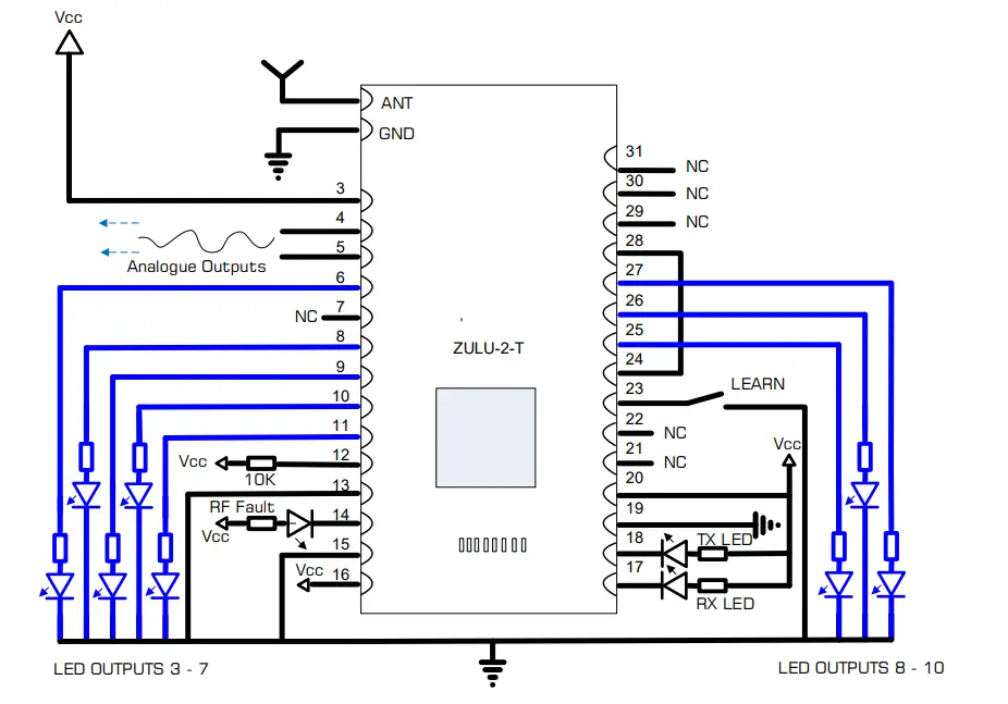
Notes
Watchdog is ON Channel Selected is 869.500 Analogue outputs active
Application Example ONE to ONE 
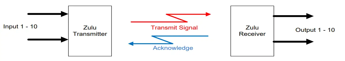
In this application the outputs at the receiver will track the inputs at the transmitter. The receiver outputs are acknowledged back to the transmitter.
If required the Watchdog can be enabled to inform the user if the RF system has a fault.
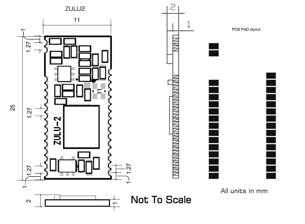
Mechanical Dimensions 
Range
The antenna choice and position directly controls the system range. Keep it clear of other metal in the system. The best position by far, is protruding vertically from the top of the product. This is often not desirable for practical reasons and thus a compromise may be needed. Note that the space around the antenna is as important as the antenna itself. All radio systems are dependant on a radio signal being received through airspace.
The range quoted is the optimal in direct line of sight without obstacles and in good atmospheric conditions.
Range is affected by many things, for example local environmental conditions, atmospheric conditions, interference from other radio transmitters. For evaluating the local environment please see our RF Meter (DS006)
In very worse case applications the range quoted may be reduced below 30% of the optimal range stated.
Recommended Miniature Antenna 868MHz
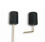
The BEAD Antenna provides a Miniature PCB mounting solution where performance is required from a small space. Available as straight or 90 degree mount this antenna is a general purpose omni-directional. Please see Datasheet: ANT-BEAD-868.
ZULU2 module Version Identification 
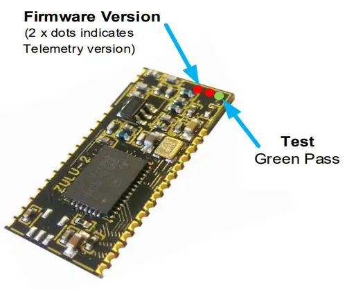
| Firmware versions Uses std Colour Coding | |
| Colour Dot | Rev |
| Brown | 1 |
| Red | 2 |
| Orange | 3 |
| Yellow | 4 |
| Green | 5 |
| Blue | 6 |
| Violet | 7 |
| Grey | 8 |
| White | 9 |
| ZETAPLUS REVISION CHANGE HISTORY | |||
| ECN | New Revision | Ident Dot | Change / Fix |
|
277 |
1.6 |
Red | Reason for Change: ZULU Locks up on saving in OTA Configuration mode. ZULU Locks up when entering local Configuration mode and exiting in succession. Details of Change Update to FW to clear stack pointer to prevent stack overflow same reason for both issues. Impact / risk analysis The parts will function but a chance they may fail in rare occasions. OTA function will not work correctly. |
| 312 | 3 | Orange | Change of Firmware only Addition of User selectable frequency Band 868 / 915MHz |
Technical Specifications
Absolute Maximums
Temperature Range: Storage –50 to +125oC. DC Characteristics
| Parameter | Min | Max | Units |
| Supply Voltage | 3.6 | V | |
| Voltage on any Input VDD >2.2V VDD <2.2V | 5.8 VDD + 3.6 | V V | |
| Max Input power (thro Antenna) | +5 | dBm |
| Parameter | Min | Typical | Max | Units |
| Supply Voltage | 2.2 | 3.6 | V | |
| Operating Temperature | -40 | +85 | oC | |
| ZULU2 TX Supply Current: When Transmitting When sleeping When used as analogue module will not sleep | 85 <1 | mA uA | ||
| ZULU2 RX Supply Current: | 18.5 | mA |
AC Characteristics
| Parameter | Min | Typical | Max | Units |
| Operating Frequency 1 Operating Frequency 2 | 869.500 868.133 | MHz MHz | ||
| Operating Temperature | -40 | +85 | oC | |
| ZULU2 TX Output Power | +20 | dBm | ||
| ZULU2 TX—RX FSK Raw RF Data Rate | 9.6 | Kbps | ||
| ZULU2 Rx Sensitivity | -121 | dBm |
System Characteristics
| Parameter | Min | Typical | Max | Units |
| Time from ZULU2 TX input activation time to ZULU2 RX output Activation | 28 | ms | ||
| Time from ZULU2 TX input activation time to ZULU2 RX output Relaxing | 28 | ms |
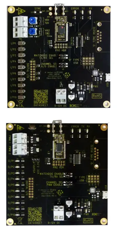
ZULUT Evaluation Board
The ZULU EVAL Boards provide a ready to go platform which can be used for evaluation or complete projects. These boards demonstrate the capabilities of ZULU Modules.
Features
- Provides a Radio Link with;
- 10 Digital Channels
- 2 Analogue Channels (PWM)
- Watchdog Feature
- Direct Antenna Connection
- 9-12Vdc Power in Terminal
- LED Indication of
- Power
- Transmit / Receiver
- RF Error
The Evaluation boards are sold as a TX and RX PCB pair, ready for component use.
Ordering Information
| Part No | Description |
| ZULU-EVALT | Tx and RX PCB Pair |
| PSU-12V1A-UK | Power Supply 12V 100mA |
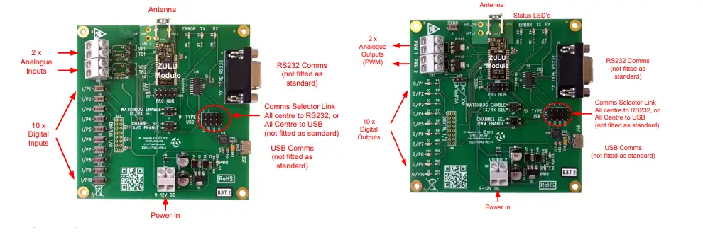
ZULUT Evaluation Board Configuration Overview
 Overview
When paired together the outputs of the receiver will follow the inputs at the transmitter. The serial outputs also provide data from the receiver.
To get up an running complete the following;
- Set the jumper links as below
- Screw in Antenna
- Apply power
- Pair together the receiver and transmitter board
| Reference | Name | When Fitted | When Open |
| J3 | A/D | I/O 1 & 2 are analogue operation | I/O 1 & 2 are set to Digital operation |
| J3 | PWM Enable | Enables PWM Output | Output’s 1& 2 set to Digital |
| J3 | Channel Select | ZULU operates on Channel A | ZULU operates on Channel B |
| J4 | TX/ RX Select | ZULU set as Receiver | ZULU set as Transmitter |
| J4 | Watchdog Enable | Watchdog enabled | Watchdog Disabled |
| LK1-LK4 | Comms Select | All links from Centre to USB All links from Centre to RS232 | N/A |
| LK5 (Receiver) | PWM Supply | Vcc: PWM is powered from Vcc VSUPPLY: PWM is powered from incoming V supply at TB1 |
Pairing Process
In order to pair together a Transmitter and receiver,
- On the Receiver Briefly press the Receiver ‘Sync Button’
- Briefly operate any of the transmitter buttons
For all other operation please refer to the ZULU Module operation.
Analogue in / PWM Out
When using the analogue RF link, by turning the potentiometer VR1 or VR2, outputs 1 and 2 at the receiver will vary between 0 and 100% PWM, the EVAL-T board has these outputs connected to LED’s 1 and 2 which will ‘dim’ their brightness with the adjustment of the transmitter VR1 and 2.
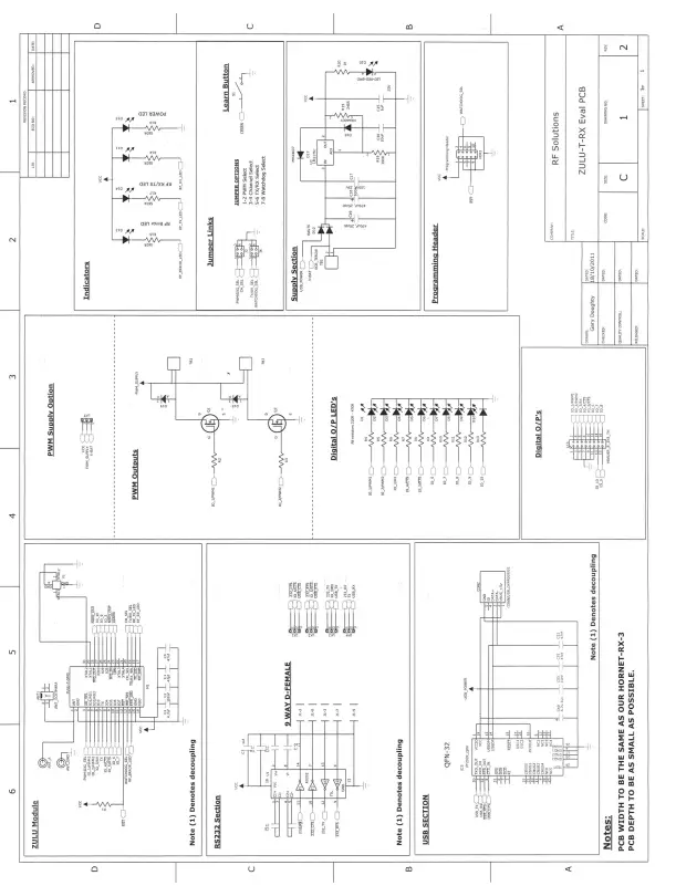
ZULU evaluation board receiver schematic ZULU evaluation board transmitter PCB layout
 ZULU evaluation board transmitter PCB layout
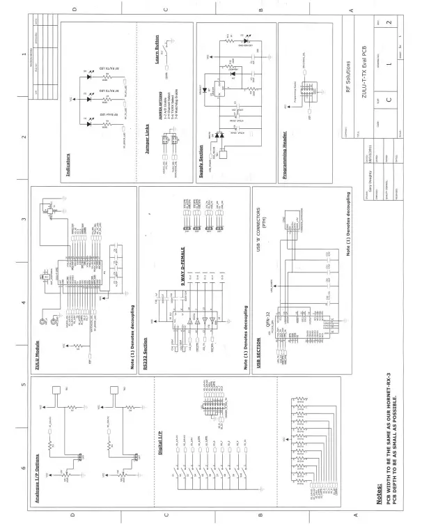
Simplified Declaration of Conformity (RED)
Hereby, RF Solutions Limited declares that the radio equipment type defined within this document is in compliance with Directive 2014/53/EU. The full text of the EU declaration of conformity is available at the following internet address: www.rfsolutions.co.uk
RF Solutions Ltd. Recycling Notice
Meets the following EC Directives
DO NOT Discard normal waste, please recycle. ROHS Directive 2011/65/EU and amendment 2015/863/EU Specifies certain limits for hazardous substances.
WEEE Directive 2012/19/EU
Waste electrical & electronic equipment. This product must be disposed of through a licensed WEEE collection point. RF Solutions Ltd. fulfils its WEEE obligations by membership in an approved compliance scheme.
Environment Agency producer registration number: WEE/JB0104WV.
Disclaimer
Whilst the information in this document is believed to be correct at the time of issue, RF Solutions Ltd does not accept any liability whatsoever for its accuracy, adequacy or completeness. No express or implied warranty or representation is given relating to the information contained in this document. RF Solutions Ltd reserves the right to make changes and improvements to the product(s) described herein without notice. Buy-ers and other users should determine for themselves the suitability of any such information or products for their own particular requirements or specification(s). RF Solutions Ltd shall not be liable for any loss or damage caused as a result of the user’s own determination of how to deploy or use RF Solutions Ltd’s products. Use of RF Solutions Ltd products or components in life support and/or safety applications is not authorised except with express wrote approval. No licences are created, implicitly or otherwise, under any of RF Solutions Ltd’s intellectual property rights. Liability for loss or damage resulting from or caused by reliance on the information contained herein or from the use of the product (including liability resulting from negligence or where RF Solutions Ltd was aware of the possibility of such loss or damage arising) is excluded. This will not operate to limit or restrict RF Solutions Ltd’s liability for death or personal injury resulting from its negligence.


