Jay electronique S5 2.4GHz Radio Module
Document edited by: Conductix Wampfler – Jay Electronique Date: December 10, 2020
Conductix-Wampfler Jay Electronique
ZAC La Bâtie | 37, rue Champrond | 38334 Saint-Ismier Cedex France www.conductix.com
ABOUT MANUAL
This module installation manual is only intended for the module integration in products manufacture of Jay electronique. All recommendations described in this document about this module also extends to the host product instruction manual. Only persons who are ability and who have training deliver by jay electronique are authorized to change this module in the products.
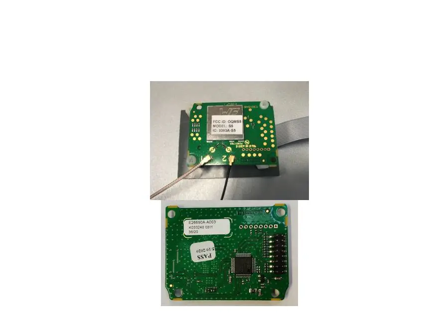
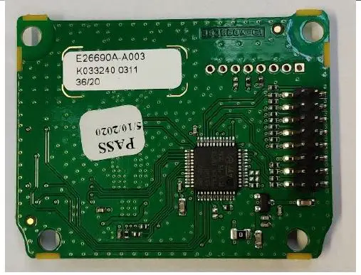
PRODUCT DESCRIPTION
This radio transceiver provides range communication in the band 2.4GHz. The radio module is completely shielded and certified for operation under the US radio regulations for license-free use.
Features
- 2.4GHz transceiver
- High sensitivity
- High-efficiency PA
- Low energy consumption
- DSSS & FSK & GFSK supported modulations
- Excellent blocking immunity
- Easy to use data interface
- Conform with FCC CFR 47 part 15
Applications
Remote-controlled machines Cranes
QUICK REFERENCE DATA
| Parameter | Module |
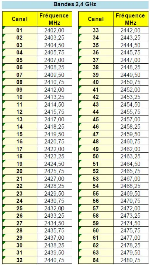
| Frequency band | 2400 – 2483.5 MHz |
| Number of channels | 64 |
| Channel bandwidth | 1.25 MHz |
| Data rate | 44.4 Kb/s |
| Max output power (typ.) | + 10 dBm |
| Sensitivity | -120 dBm |
| Supply voltage | 3.3 to 4.2 Vdc |
| Current consumption, RX | 10 mA |
| Current consumption, TX | 15 to 45 mA |
PIN DESCRIPTION
| Pin no | Pin name | Description |
| 1 | EN_PA | PA / Switch Rx – Tx |
| 2 | PWRF2 | Not used |
| 3 | RTS_TXEN_RADIO | Not used |
| 4 | CTS/RXTX/RXEN_RADIO | Not used |
| 5 | VAccu | Supply voltage input |
| 6 | GND | System ground |
| 7 | SPI_uc_SCK/ON_OFF | SPI Clock |
| 8 | SPI_uc_MISO | SPI MISO |
| 9 | SPI_uc_MOSI | SPI MOSI |
| 10 | RESET_RADIO | Reset |
| 11 | SEL_FILLE | Download microcontroller firmware |
| 12 | SPI_uc_NSS/CONFIG_RADIO | SPI Chip Select |
| 13 | RSSI_RADIO | Not used |
| 14 | DATA_RX | UART RX Data |
| 15 | DATA_TX | UART TX Data |
| 16 | GND | System ground |
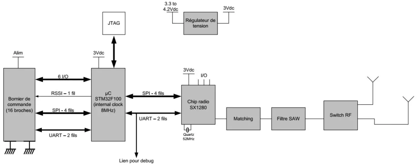
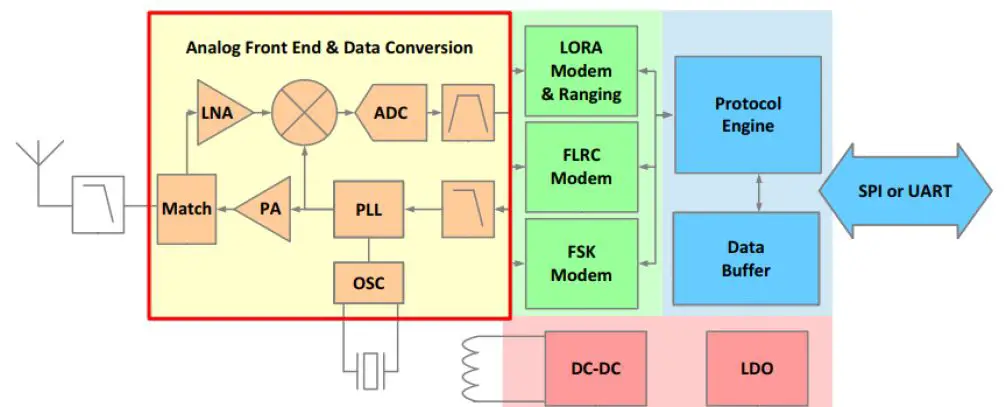
BLOCK DIAGRAM
CHIP RADIO
The chip radio used is the SX1280 of SEMTECH company. The SX1280 are half-duplex transceivers capable of low power operation in the worldwide 2.4 GHz ISM band. The radio features a high-efficiency transmitter and a high linearity receive chain that are both accessed via a common antenna port pin. Frequency conversion between RF and baseband (low-IF) is governed by a digital PLL that is referenced to a 52 MHz crystal. Both transmit and receive chains are interfaced by data converters to the ensuing digital. The analog front end features a single antenna port connection to an integrated matching circuit that permits half- duplex operation of the radio without external RF switching.
Transceiver Block Diagram:
The modem uses spread spectrum modulation and Forward Error Correction (FEC) techniques to increase the range and robustness of radio communication links.
In this modulation the spreading of the spectrum is achieved by generating a chirp signal that continuously varies in frequency. An advantage of this method is that timing and frequency offsets between transmitter and receiver are equivalent, greatly reducing the complexity of the receiver design. The frequency bandwidth of this chirp is equivalent to the spectral bandwidth of the signal.
The wanted data signal is chipped at a higher data rate and modulated onto the chirp signal.
The relationship between the wanted data bit rate, symbol rate and chip rate for the modulation can be expressed as follows:
We can define the modulation bit rate, Rb, as: Rb = SF * 1 / [2SF/BW] bits/sec Where:
Rb = Raw Data Rates
SF = spreading factor (7..12)
BW = modulation bandwidth (Hz)
Below principal parameters configured in the radio chip SX1280:
- Type of modulation: spread spectrum modulation
- Raw Data Rates: 44 kb/s (SF7)
- Bandwidth: 812 kHz
FCC STATEMENT
The OEM integrators are responsible for ensuring that the end-user has no manual instructions to remove or install-module.
The following instructions/statements shall be reported on the User Manual:
This device complies with Part 15 of the FCC Rules.
Operation is subject to the following two conditions: (1) this device may not cause harmful interference, and (2) this device must accept any interference received, including interference that may cause undesired operation.
Caution: the user that changes or modifications not expressly approved by the party responsible for compliance could void the user’s authority to operate the equipment.
NOTE: This equipment has been tested and found to comply with the limits for a Class B digital device, pursuant to part 15 of the FCC Rules. These limits are designed to provide reasonable protection against harmful interference in a residential installation. This equipment generates, uses and can radiate radio frequency energy and, if not installed and used in accordance with the instruction,may cause harmful interference to radio communications. However, there is no guarantee that interference will not occur in a particular installation. If this equipment does cause harmful interference to radio or television reception which can be determined by turning the equipment off and on, the user is encouraged to try to correct interference by one or more of the following measures:
- Reorient or relocate the receiving antenna.
- Increase the separation between the equipment and receiver.
- Connect the equipment into an outlet on circuit different from that to which the receiver is connected.
- Consult the dealer or an experienced radio/TV technician for help.
This device complies with FCC radiation exposure limits set forth for general population.
This device must not be co-located or operating in conjunction with any other antenna or transmitter.
The radio module must be labelled as follows:
FCC ID: OQMS5
Moreover, the host equipment must be labelled as follows:
Contains FCC ID: OQMS5, Model S5, IC: 3393A-S5
Warning:
This module is used exclusively by JAY Electronique. This product and the antennas must be professionally installed.
IC STATEMENT
The OEM integrators are responsible for ensuring that the end-user has no manual instructions to remove or install-module.
These following instructions/statements shall be reported on the User Manual:
This radio transmitter (3393A-S5) has been approved by Industry Canada to operate with the antenna types listed below with the maximum permissible gain and required antenna impedance for each antenna type indicated. Antenna types not included in this list, having a gain greater than the maximum gain indicated for that type, are strictly prohibited for use with this device.
This device contains license-exempt transmitter(s)/receiver(s) that comply with Innovation, Science, and Economic Development Canada’s license-exempt RSS(s). Operation is
subject to the following two conditions:
- this device may not cause interference, and
- This device must accept any interference, including interference that may cause undesired operation of the device.
This device complies with ISED and FCC radiation exposure limits set forth for general population. This device must not be co-located or operating in conjunction with any other antenna or transmitter.
The radio module must be labelled as follows:
FCC ID: OQMS5
Moreover, the host equipment must be labelled as follows:
Contains FCC ID: OQMS5, Model S5, IC: 3393A-S5
Warning:
This modular is used exclusively by JAY Electronique. This module and the antennas must be professionally installed.
| N° | Manufacturer | Reference |
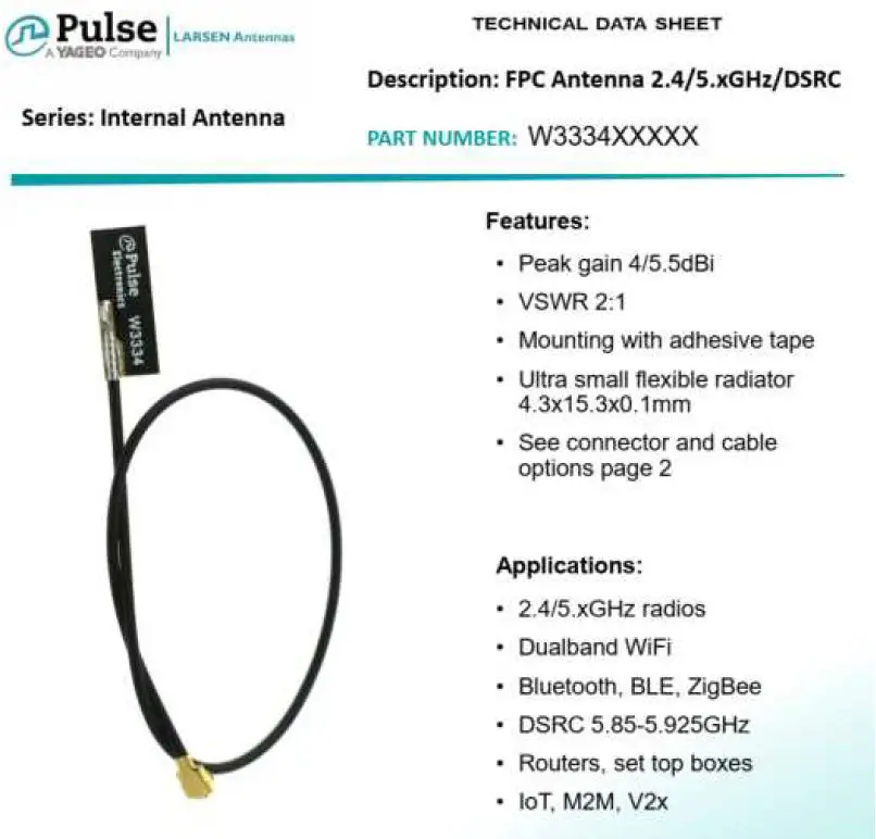
| 1 | Pulse | W3334B0100 |
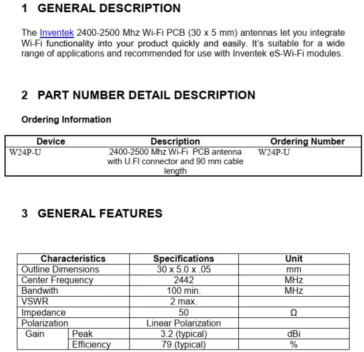
| 2 | Inventek Systems | W24P-U |
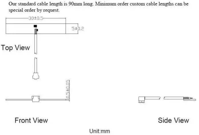
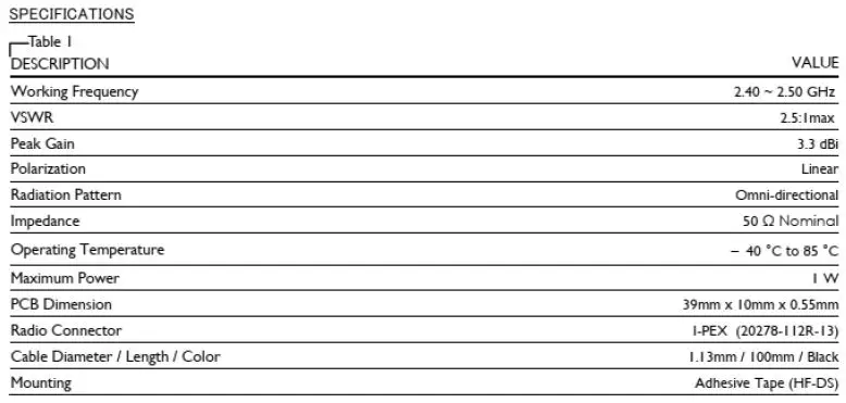
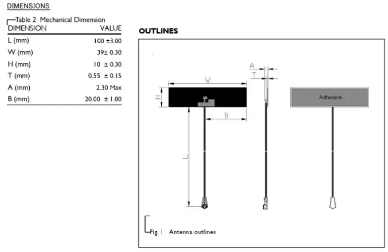
| 3 | Yageo | ANTX100P111B24003 |
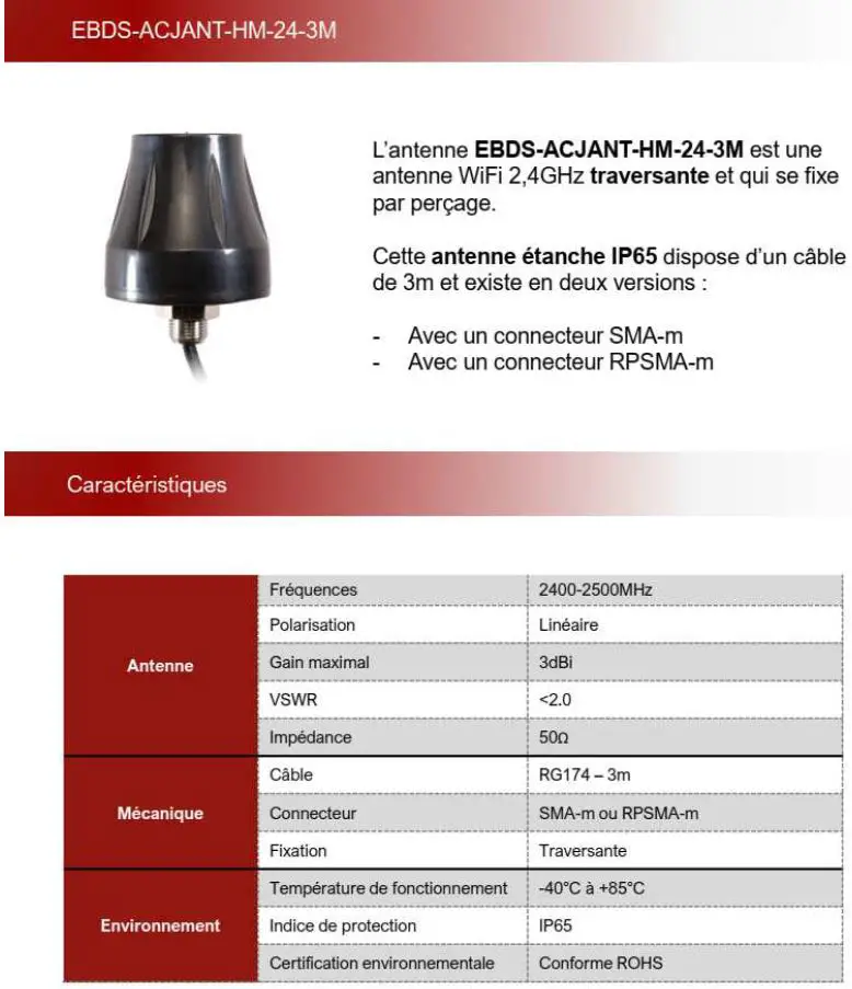
| 4 | EBDS | EBDS-ACJANT-HM-24-3M |
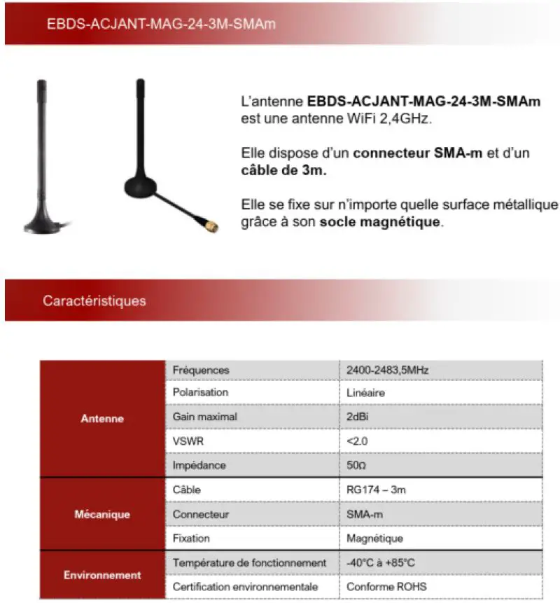
| 5 | EBDS | EBDS-ACJANT-MAG-24-3M-SMAm |
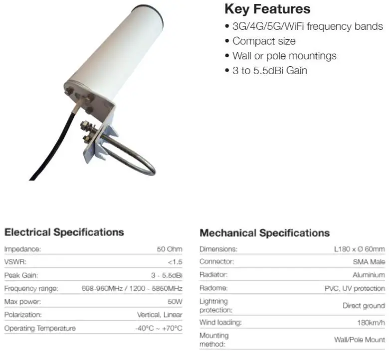
| 6 | Sirreta | OSCAR40/5M/LL/SMAM/S/S/33 |
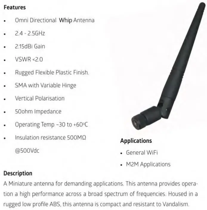
| 7 | RF solution | ANT-24G-WPJ-SMA |
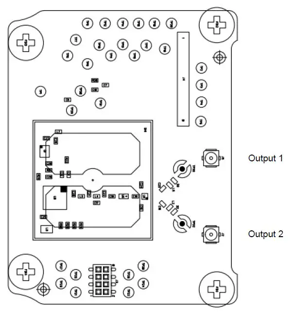
Antennas numbers 1, 2, and 3 can be connected directly to connector UFL on the radio board module. For antennas 4, 5, 6, and 7 it is necessary to have adaptor UFL to SMA females for connected these.
Not ground systems are necessary for installing the antenna and radio module.
Pulse
Inventek System
REVISION HISTORY
| Row | Revision Date | Revision Description | By |
| 1 | 9-12-2020 | Initial version | P.Fourey |
| 2 | 17/12/2020 | Modification of §5 paragraph | P.Fourey |
| 3 | 4/01/2021 | Correction | P.Fourey |
| 4 | 5/01/2021 | Modification §5 and §6 paragraph | P.Fourey |
| 5 | 17/03/2021 | Add “Chip radio” paragraph” | P.Fourey |
| 6 | 26/04/2021 | Add “About manual” paragraph | P.Fourey |
| 7 | 04/06/2021 | Modification “About manual” paragraph | P.Fourey |


