
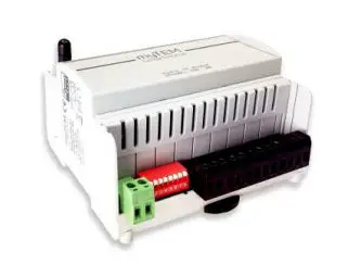
myTEM SmartHome MTIOM-101-WL Radio IO Modul Floor
SAFETY INSTRUCTIONS
- Operate this device only as described in the manual.
- Do not operate this device if it has obvious damage.
- This device shall not be altered, modified, or opened.
- This device is intended for use in buildings in a dry, dust-free location.
- This device is intended for installation in a control cabinet. After installation, it must not be openly accessible.
- Electrical equipment may only be installed and fitted by qualified electricians who are familiar with and comply with the applicable regulations and standards.
- Analog inputs/outputs, digital inputs, and device supply must comply with the ELV requirements. Do not connect ELV and mains voltage together. (ELV = extra-low voltage)
- If several motors are to be connected in parallel at one output, be sure to observe the manufacturer’s instructions and, if necessary, use isolating relays.
- Only use blind motors with mechanical or electronic limit switches. Limit switches must be checked for correct adjustment.
- Do not connect three-phase motors.
DISCLAIMER All rights reserved. This is a translation from the original version in German.
This manual may not be reproduced in any format, either in whole or in part, nor may it be duplicated or edited by electronic, mechanical, or chemical means, without the written consent of the publisher.
The manufacturer, TEM AG, is not liable for any loss or damage caused by failure to follow the instructions in the manual. Typographical and printing errors cannot be excluded. However, the information contained in this manual is reviewed on a regular basis and any necessary corrections will be implemented in the next edition. We accept no liability for technical or typographical errors or the consequences thereof. Changes may be made without prior notice as a result of technological advances. TEM AG reserves the right to make changes to product design, layout, and driver revisions without notice to its users. This version of the manual supersedes all previous versions.
- Trademarks
TEM and TEM are registered trademarks. All other product names mentioned herein may be trademarks or registered trademarks of their respective companies. What is Z-Wave®? - Wave is the international wireless protocol for communication in the smart home. Z-Wave ensures reliable communication by reconfirming every message (two-way communication) and every mains-powered node can act as a repeater for other nodes (meshed network) in case the receiver is not in direct wireless range of the transmitter.
- Wave products from different manufacturers can be used together in a wireless network. Thus, this product with any Z-Wave product from other manufacturers can be used in a common Z-Wave wireless network. All mains operated nodes within the network will act as repeaters regardless of vendor to increase the reliability of the network.
The system Radio IO Modul and the system Radio IO Modul Floor are Z-Wave devices with secure communication (S2) and use the radio frequency of 868.4 MHz. If other devices also support the same secure communication, the data is exchanged in this secure mode. Other-wise it will switch automatically to a lower level of security to maintain backward compatibility.
For more information about frequency regulations please refer to the homepage of Silicon Labs. For more information about Z-Wave technology, devices, tutorials, etc. please refer to www.z-wave.info.
Product description
The system Radio IO Modul and the system Radio IO Modul Floor are Z-Wave devices of the type Binary Switch for use in Europe / Switzerland.
- Switching of lights
- Switching of single-phase fan motors
- Switching of electric blinds or similar shading devices
- Operation by means of buttons, sensors via the central server
Functions
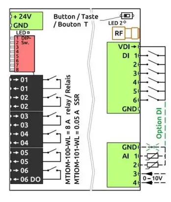
- Supply voltage 24 VDC ± 10%
- Communication via Z-Wave mesh network
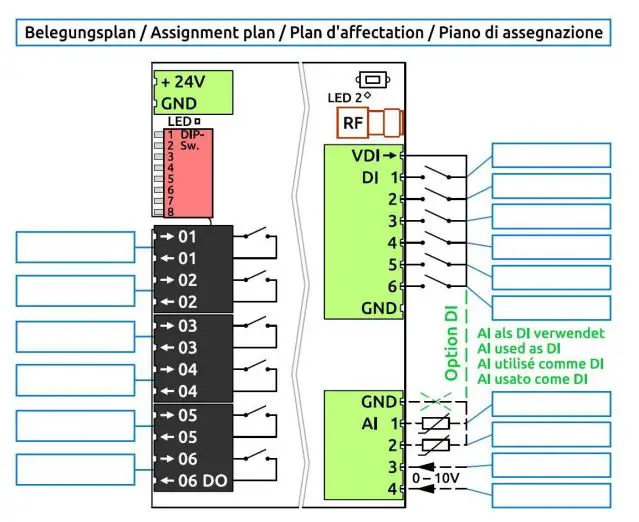
- 6 digital inputs 24 VDC (DI1 – DI6) for e.g. external switches
- 24 VDC power supply, 100 mA, for the digital inputs DI1 – DI6 (VDIout)
- 4 analog inputs (AI1 – AI4), which can be used for 0-10 VDC or NTC-, PTC- or PT1000 sensors. Analog inputs can also be used as digital inputs 24 VDC. They must then beconnectedtoVDIout.
- 6 digital outputs with potential-free relays 8 A, 250 VAC or 30 VDC (DO1 – DO6) in case of the system Radio IO Modul and noiseless SSR 0.05 A, 250 VAC in case of the Radio IOModulFloor.
- Manual positions of the outputs via DIP switch for easy commissioning
- The device is installed in a control cabinet, mounted on a 35 mm DIN rail
Preparation for the installation
In order to include (“Add”) a Z-Wave device to a network, it must be in the factory default state. Please make sure to reset the device into factory default. After power-up the status is displayed as below: Status “Add” (included in a Z-Wave network): The LED 2 lights green for 1-2 secondsStatus “Remove” (not included): The LED 2 flashes red for 1-2 seconds device Reset Locally (Reset to)Please use this procedure only when the network primary controller is missing or otherwise inoperable. Power up the device and then press the button (T) for 10 seconds. Reset The LED lights up briefly in red The device reset deletes the memory chip, including all Z-Wave network settings.
Installation
WARNING! Depending on national safety standards, only authorized and/or trained technicians may be allowed to perform electrical installations on the power grid. Please inform yourself about the legal situation before installation.
WARNING! Different voltages (e.g. 24 VDC, 230 VAC L1 or 230 VAC L2) may only be connected to the digital outputs (relays / SSRs) if one output is left out between them.
Please install the device according to the following steps:
- WARNING! Make sure that the device is disconnected from the power supply or that the devices in the control cabinet are disconnected from the mains.
- WARNING! Connect the device according to the circuit diagram of the system ProgTool or the terminal assignment from the pictures in this manual. Incorrect wiring can result in injury ordeaththe de-vice.
- CAUTION! The device shall only be operated with stabilized power supplies (24 VDC). Connecting to higher voltages will damage the device.
- WARNING! Switch on the power supply and, if necessary, check the wiring with the manual positions via the DIP switch. Take care of your safety as the de-vices are live.
- Include (Add) the module into the Z-Wave network as described below.
Inclusion/Exclusion (“Add/Remove”) of the device
On factory default, the device does not belong to any Z-Wave network. In order to communicate with other Z-Wave devices, it must be included in an existing network or a new network has to be established. In Z-Wave, this process is called “Add”.
Devices can also be removed from networks. In Z-Wave, this process is called “Remove”. The primary controller of the Z-Wave network initiates both processes. This controller is put into the “Add”, respectively the “Remove” mode. The manual of the controller will contain the information on how to switch it into these modes. Only when the primary controller of the Z-Wave network is in the “Add” mode can devices be added. Removing a device from the network will reset it to the delivery state.
SmartStart
SmartStart-enabled products can be added to a Z-Wave network by scanning the Z-Wave QR code present on the product with a controller providing SmartStart inclusion. No further action is required and the SmartStart product will be added automatically within 10 minutes of being switched on in the network vicinity. The DSK label (QR code) is located on the long side of the housing. When the device is in the “Add” mode, the LED flashes green.
When finished, the new status is:
- Add: The LED 2 lights up briefly in green
- Remove: The LED 2 lights up briefly in red
Manual inclusion/exclusion (“Add/Remove”)
If the system Radio IO Modul or system Radio IO Modul Floor shows the status “Add”, the “Remove” can be performed with any controller in the network or with the help of a new controller. However, it is recommended to use the primary controller of the previous network unless it is no longer available or damaged.
“Remove” deletes the memory chip, including all Z-Wave network settings.
- Activate the “Add” or “Remove” mode on your controller.
- Press the button (T) four times in quick succession to start to include/exclude (“Add / Remove”).
When the device is in the “Add” mode, the LED flashes green.
When finished, the new status is:
- Add: The LED 2 lights up briefly in green
- Remove: The LED 2 lights up briefly in red
Manual positions via DIP switch With the aid of the DIP switch, the outputs can be checked after installation.
- CAUTION! While manual settings are used, the control commands from the system Smart Server or system Radio Server are ignored.
- CAUTION! Before starting, set all DIP switches to position OFF, i.e. upwards. This avoids that e.g. OPEN / CLOSE commands are set at the same time.
- To check the digital outputs (relays / SSRs) set DIP switch 8 down to ON. With the DIP switches 1 – 6 you can now switch the outputs DO1 – DO6 on and off.
- LED 1 display The LED 1 next to the power connector may show the following states:
- LED 1 green: The device started and worked according to commands from the system Smart Server or system Radio Server
- LED 1 flashing green: The device is in the manual position, i.e. the outputs are according to the DIP-switch setting
- LED 1 off: Device not powered, not started or bro-ken
Quick troubleshooting
The following hints may help solve trouble:
- Make sure that the power supply is connected with the correct polarity. With the wrong polarity, the device does not start.
- Make sure that new devices are in the factory reset state. The Z-Wave status is displayed at power-up.
- If a connection cannot be established, check that the controller and the device are working on the same radio frequency.
- If a connection cannot be established, the control cabinet may reduce the radio signal. Please use in this case an external antenna, such as, for example, the myTEM MTANT-100-WL.
- Remove devices that are no longer available in the Z-Wave network from all association groups. Otherwise, significant delays in the execution of commands are possible.
- Make sure you have enough mains-powered devices to benefit from the meshing network.
- Never use “sleeping” battery-powered devices without a central controller and do not poll battery-powered devices
Technical specifications
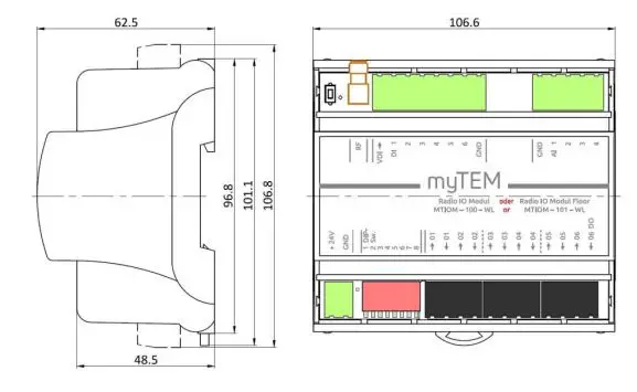
| Dimensions (W × H × D) | 106.6 × 101.1 × 62.5 mm (height with connectors 106.8 mm) | |
| Installation / mounting | On 35 mm DIN rail | |
| Operating voltage | 24 VDC ± 10% | |
| Power consumption in standby | Continuous operation for a wireless network, therefore no standby operation | |
| Power consumption in operation (module only, without external loads) | 0.5 W, if the inputs are open and the outputs are turned off 5.0 W, if the inputs are short-circuited to VDIout and the outputs are turned on | |
| Switchable load | MOM-100-WL MTIOM-101-WL | 6× 8.0 A, 250 VAC or 30 VDC, cos(φ) =1.0 (Relay version – Radio IO Modul) 6× 0.05 A, 250 VAC or 30 VDC, cos(φ) =1.0 (SSR version – Radio IO Modul Floor) |
| Ambient temperature for operation | 0 °C – 50 °C | |
| Ambient temperature for storage | -20 °C – 60 °C | |
| Ambient humidity | 5 %RH – 85 %RH (non condensing) | |
| Wire cross-section connectors | 0.25 mm² – 2.5 mm² | |
| Stripping length for connectors | ca. 7 mm | |
| Tightening torque for connectors | 0.5 Nm | |
| Degree of protection provided by the enclosure | IP 20 (after installation) (according to EN 60529) | |
| Protection class | II (according to EN 60730-1) | |
| Overvoltage category | II (according to EN 60730-1, resp. EN 60664-1) | |
| Pollution degree | 2 (according to EN 60730-1) | |
| Safety main unit | EN 60730-1:2016 + A1:2019 | |
| EMC main unit | EN 60730-1:2016 + A1:2019 EN IEC 61000-6-2:2019 EN 61000-6-3:2007 + A1:2011 / AC:2012 | |
| Safety radio part | EN 62368-1:2014 / AC:2017 EN 62479:2010 | |
| EMC radio part | EN 301 489-1 V2.2.3 EN 301 489-3 V2.1.1 | |
| Radio spectrum | EN 300 220-2 V3.2.1 | |
| RoHS | EN IEC 63000:2018 | |
| CE conformity | 2014/35/EU (LVD) 2014/53/EU (RED) 2014/30/EU (EMC) 2011/65/EU (RoHS) | |
| Z-Wave hardware platform | Z-Wave series 700 (ZGM130) | |
| Device Type | Binary Switch | |
| Role Type | Always On Slave (AOS) | |
Explanation of some Z-Wave specific terms
The controller… is a Z-Wave device with the capability to manage a network. They are typically gateways, remote controls, or wall controllers.
The primary controller … is the central administrator of the Z-Wave network. In a Z-Wave network, only one primary controller is allowed.
Slave … is a Z-Wave device without the ability to manage a network. Slaves can be sensors, actuators, and even remote controls.
Add (Inclusion) … is the process of adding new Z-Wave devices into a network.
Remove (Exclusion) … is the process of removing Z-Wave devices from the network.
Wakeup Notification … is a special wireless message issued by battery-powered Z-Wave devices to announce that they are awake and able to communicate.
Node Information Frame (NIF) … is a special wireless message issued by a Z-Wave device to announce its capabilities and function
Z-Wave Association – Devices control each other
The Association Command Class is used to manage associations to NodeID destinations. An association group sends commands to the config-ured destinations when triggered by an event.
Association groups:
| Group ID | Profile / Name | Max. no of units | Command Class | Type / Event | Description |
|
1 |
General: Lifeline / Lifeline |
5 |
Notification Report | T: System (0x09) E: Heartbeat (0x05) | Reports to be alive (interval according to configuration) |
| T: Power Management (0x08) E: Power has been applied (0x01) | Reports the device had a start-up (sent after each power-up only) | ||||
| Device Reset Locally | Reports resetting network and configuration parameter | ||||
| Central Scene | Actuation of digital inputs DI1 – DI6 |
The reports “Heartbeat” and “Power Management” can be activated/deactivated separately via the command class Notification.
Endpoints 1 … 6 (DO1 – DO6, n = 1 … 6)
Each endpoint reflects a digital outpu
| Group ID | Profile / Name | Max. no of units | Command Class | Description |
| 1 | General: Lifeline / Lifeline | 5 | Binary Switch Report | Reports output DO<n> state, when it changed |
Endpoints 7 … 12 (DI1 – DI6, n = 1 … 6)
Each endpoint reflects a digital input.
| Group ID | Profile / Name | Max. no of units | Command Class | Type / State | Description |
| 1 | General: Lifeline / Lifeline | 5 | Notification Report | T: System S: High state / Open | Report “Open” (input open), “High state” (input closed) DI<n> |
| Group ID | Profile / Name | Max. no of units | Command Class | Type / State | Description |
| 1 | General: Lifeline / Lifeline | 5 | Notification Report | T: System S: High state / Open | Report “Open” (input open), “High state” (input closed) DI<n> |
Endpoints 13 … 16 (AI1 – AI4, n = 1 … 4)
Each endpoint reflects an analog input.
| Group ID | Profile / Name | Max. no of units | Command Class | Description |
| 1 | General: Lifeline / Lifeline | 5 | Multilevel Sensor Report | Temperature or voltage value input AI<n> |
| 5 | Multilevel Sensor Supported Report | Reports the actual supported sensor type (temperature or voltage) |
- Wave configuration parameters
- Wave products can be used out of the box after inclusion (“Add”) into the network. With the configuration, however, the behavior can be better adapted to the application. CAUTION! Depending on the function the server may change some default settings
| Par# | Description | Unit | Min | Max | Default | Digits | R/W | Size | |
| 1 | Heartbeat rate | min | 1 | 1440 | 60 | 0 | r/w | 2 bytes | |
| 2 | Digital input 1 type | (0 = disabled; 1 = binary / Binary Sensor Report; 2 = key / Central Scene Report) X) | – | 0 | 2 | 0 | 0 | r/w | 2 bytes |
| 3 | Digital input 1 sends interval | min | 0.1 | 120.0 | 5.0 | 1 | r/w | 2 bytes | |
| 4 | Digital input 2 type (see Par# 2) X) | – | 0 | 2 | 0 | 0 | r/w | 2 bytes | |
| 5 | Digital input 2 sends interval | min | 0.1 | 120.0 | 5.0 | 1 | r/w | 2 bytes | |
| 6 | Digital input 3 types (see Par# 2) X) | – | 0 | 2 | 0 | 0 | r/w | 2 bytes | |
| 7 | Digital input 3 sends interval | min | 0.1 | 120.0 | 5.0 | 1 | r/w | 2 bytes | |
| 8 | Digital input 4 types (see Par# 2) X) | – | 0 | 2 | 0 | 0 | r/w | 2 bytes | |
| 9 | Digital input 4 sends interval | min | 0.1 | 120.0 | 5.0 | 1 | r/w | 2 bytes | |
| 10 | Digital input 5 types (see Par# 2) X) | – | 0 | 2 | 0 | 0 | r/w | 2 bytes | |
| 11 | Digital input 5 sends interval | min | 0.1 | 120.0 | 5.0 | 1 | r/w | 2 bytes | |
| 12 | Digital input 6 type (see Par# 2) X) | – | 0 | 2 | 0 | 0 | r/w | 2 bytes | |
| 13 | Digital input 6 send interval | min | 0.1 | 120.0 | 5.0 | 1 | r/w | 2 bytes | |
| 14 | Analog input 1 enable (0 = disabled / 1 = enabled) | – | 0 | 1 | 0 | 0 | r/w | 2 bytes | |
| 15 | Analog input 1 select NTC5k (0), NTC10k (1), PTC1k (2), PT1000 (3), 0-10V (4), digital (5) | – | 0 | 5 | 0 | 0 | r/w | 2 bytes | |
| 16 | Analog input 1 sends interval | min | 0.1 | 120.0 | 5.0 | 1 | r/w | 2 bytes | |
| 17 | Minimum delta temperature 1 send Y) | K | 0.1 | 10.0 | 0.5 | 1 | r/w | 2 bytes | |
| 18 | Minimum delta voltage 1 sends Y) | V | 0.1 | 10.0 | 0.5 | 1 | r/w | 2 bytes | |
| 19 | Analog input 2 enable (0 = disabled / 1 = enabled) | – | 0 | 1 | 0 | 0 | r/w | 2 bytes | |
| Par# | Description | Unit | Min | Max | Default | Digits | R/W | Size |
| 20 | Analog input 2 select NTC5k (0), NTC10k (1), PTC1k (2), PT1000 (3), 0-10V (4), digital (5) | – | 0 | 5 | 0 | 0 | r/w | 2 bytes |
| 21 | Analog input 2 sends interval | min | 0.1 | 120.0 | 5.0 | 1 | r/w | 2 bytes |
| 22 | Minimum delta temperature 2 send Y) | K | 0.1 | 10.0 | 0.5 | 1 | r/w | 2 bytes |
| 23 | Minimum delta voltage 2 sends Y) | V | 0.1 | 10.0 | 0.5 | 1 | r/w | 2 bytes |
| 24 | Analog input 3 enable (0 = disabled / 1 = enabled) | – | 0 | 1 | 0 | 0 | r/w | 2 bytes |
| 25 | Analog input 3 select NTC5k (0), NTC10k (1), PTC1k (2), PT1000 (3), 0-10V (4), digital (5) | – | 0 | 5 | 0 | 0 | r/w | 2 bytes |
| 26 | Analog input 3 sends interval | min | 0.1 | 120.0 | 5.0 | 1 | r/w | 2 bytes |
| 27 | Minimum delta temperature 3 send Y) | K | 0.1 | 10.0 | 0.5 | 1 | r/w | 2 bytes |
| 28 | Minimum delta voltage 3 send Y) | V | 0.1 | 10.0 | 0.5 | 1 | r/w | 2 bytes |
| 29 | Analog input 4 enable (0 = disabled / 1 = enabled) | – | 0 | 1 | 0 | 0 | r/w | 2 bytes |
| 30 | Analog input 4 select NTC5k (0), NTC10k (1), PTC1k (2), PT1000 (3), 0-10V (4), digital (5) | – | 0 | 5 | 0 | 0 | r/w | 2 bytes |
| 31 | Analog input 4 sends interval | min | 0.1 | 120.0 | 5.0 | 1 | r/w | 2 bytes |
| 32 | Minimum delta temperature 4 send Y) | K | 0.1 | 10.0 | 0.5 | 1 | r/w | 2 bytes |
| 33 | Minimum delta voltage 4 send Y) | V | 0.1 | 10.0 | 0.5 | 1 | r/w | 2 bytes |
- With buttons at the input, the Central Scene Report should be used, with switches at the input the Binary Sensor Report should be used
- Delta value in relation to the last sent value
Central Scene Command
The digital inputs can be used for Central Scene Commands. The assignment of the scene number is according to the table.
| Digital input.(use buttons) | DI1 | DI2 | DI3 | DI4 | DI5 | DI6 |
| Scene number | 1 | 2 | 3 | 4 | 5 | 6 |
Supported Command Classes
Root Device
| Command Class (CC) | Version | Not added | Non-secure added | Securely added, non-secure CC | Securely added, secure CC |
| Application Status CC | 2 | Support | Support | Support | |
| Association CC | 2 | Support | Support | Support | |
| Association Group Information CC | 3 | Support | Support | Support | |
| Basic CC | 2 | Support | Support | Support | |
| Binary Switch CC | 2 | Support | Support | Support | |
| Central Scene CC | 3 | Support | Support | Support | |
| Configuration CC | 4 | Support | Support | Support | |
| Device Reset Locally CC | 1 | Support | Support | Support | |
| Firmware Update Meta Data CC | 5 | Support | Support | Support | |
| Indicator CC | 3 | Support | Support | Support | |
| Manufacturer Specific CC | 2 | Support | Support | Support | |
| Multi Channel Association CC | 3 | Support | Support | Support | |
| Multi Channel CC | 4 | Support | Support | Support | |
| Notification CC | 8 | Support | Support | Support | |
| Powerlevel CC | 1 | Support | Support | Support | |
| Security_2 CC | 1 | Support | Support | Support | |
| Supervision CC | 1 | Support | Support | Support | |
| Transport Service CC | 2 | Support | Support | Support | |
| Version CC | 3 | Support | Support | Support | |
| Z-Wave Plus Info CC | 2 | Support | Support | Support |
Announced CC in endpoints:
The inputs and outputs are mapped to the following endpoints:
| Input / Output | Fix / Dynamic | Number | Remark | Abbreviation | Default |
| Digital outputs | Fix | 6 | DO1 … DO6 | ||
| Digital inputs | Fix | 6 | DI1 … DI6 | ||
| Analog inputs | Fix | 4 | Individually selectable between: § Temperature sensor § 0-10 VDC sensor | AI1 … AI4 | Temperature sensor |
Endpoints 1 … 6 (DO1 – DO6, n = 1 … 6) Device Type: Switch Binary
| Command Class (CC) | Version | Non-secure added | Securely added, non-secure CC | Securely added, secure CC |
| Association CC | 2 | Support | Support | |
| Association Group Information CC | 3 | Support | Support | |
| Binary Switch CC | 2 | Support | Support | |
| Multi Channel Association CC | 3 | Support | Support | |
| Security_2 CC | 1 | Support | ||
| Supervision CC | 1 | Support | Support | |
| Z-Wave Plus Info CC | 2 | Support | Support |
|
Endpoints 7 … 12 (DI1 – DI6, n = 1 … 6)
- Device Type: Notification Sensor
- Sensor Type: System (0x09)
- Event/State: digital input short-circuited (0x09), digital input open (0x0B)
| Command Class (CC) | Version | Non-secure added | Securely added, non-secure CC | Securely added, secure CC |
| Association CC | 2 | Support | Support | |
| Association Group Information CC | 3 | Support | Support | |
| Central Scene CC | 3 | Support | Support | |
| Multi Channel Association CC | 3 | Support | Support | |
| Notification Sensor CC | 8 | Support | Support | |
| Security_2 CC | 1 | Support | ||
| Supervision CC | 1 | Support | Support | |
| Z-Wave Plus Info CC | 2 | Support | Support |
Endpoints 13 … 16 (AI1 – AI4, n = 1 … 4; change capabilities)
- Device Type: Multilevel Sensor
- Sensor Type: Air Temperature (0x01) / Voltage (0x0F)
- Scale: Celsius (0x00) / Volt (0x00) or mV (0x01)
| Command Class (CC) | Version | Non-secure added | Securely added, non-secure CC | Securely added, secure CC |
| Association CC | 2 | Support | Support | |
| Association Group Information CC | 3 | Support | Support | |
| Multi Channel Association CC | 3 | Support | Support | |
| Multilevel Sensor CC | 11 | Support | Support | |
| Security_2 CC | 1 | Support | ||
| Supervision CC | 1 | Support | Support | |
| Z-Wave Plus Info CC | 2 | Support | Support |


