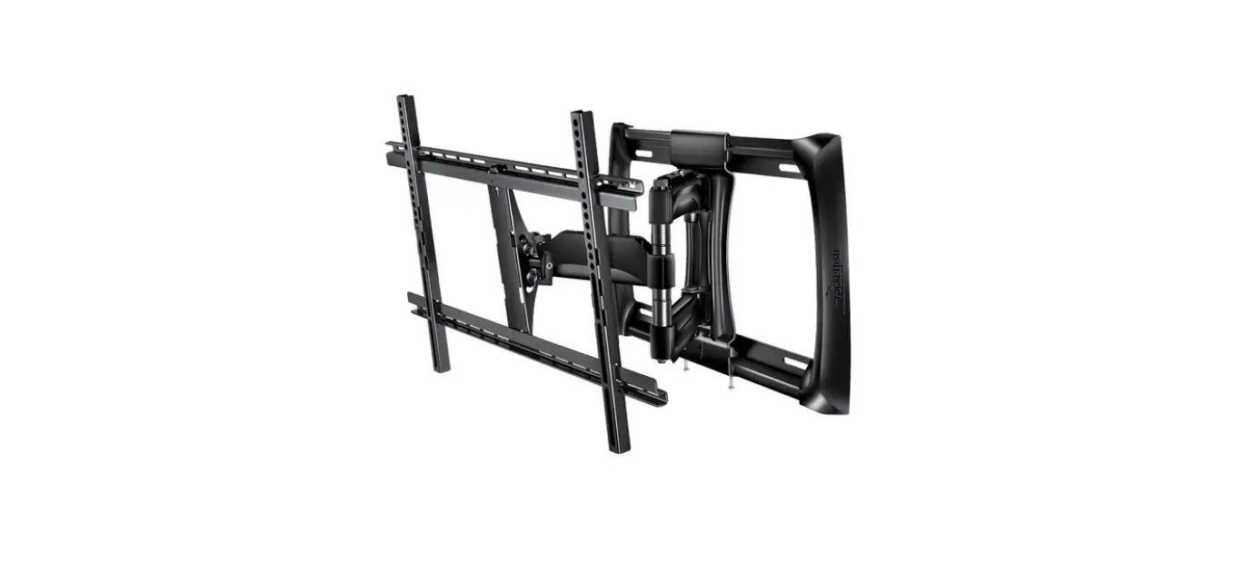
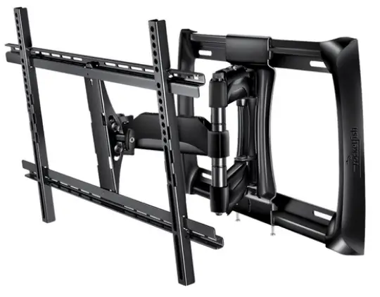
 ROCKETFISH RF-HTVMM170C TV WALL MOUNT User Manual
Safety information and specifications
- Maximum TV weight: 100 lbs. (45.3 kg)
- Screen size: 40″ to 75″ diagonal
- Overall dimensions (H × W × D): 16.7 x 24.9 x 3.5 in. (425 x 632 x 90 mm)
- Wall-mount weight: 19.4 lbs. (8.8 kg) We’re here for you
CAUTION:
Do not use this product for any purpose not explicitly specified by Rocketfish. Improper installation may cause property damage or personal injury. If you do not understand these 1-800-620-2790 (U.S. and Canada) directions or have doubts about the safety of the installation, contact Customer Service or call a qualified contractor. Rocketfish is not responsible for damage or injury caused by incorrect installation or use.The weight of your TV must not exceed 100 lbs. (45.3 kg). The wall must be capable of supporting five times the weight of your TV and wall mount combined. This product contains small items that could be a choking hazard if swallowed. Keep these items away from young children!
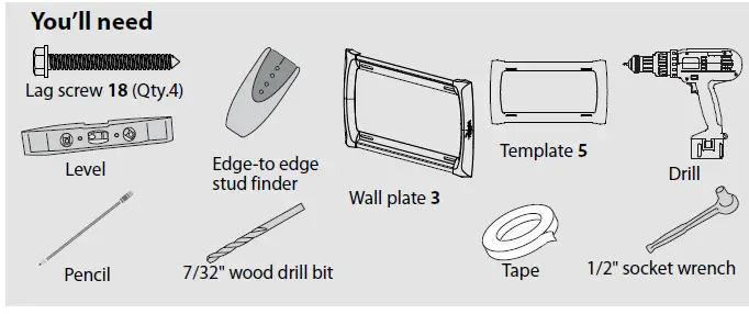
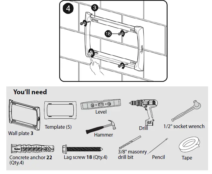
Tools needed
You will need the following tools to assemble your new TV wall mount: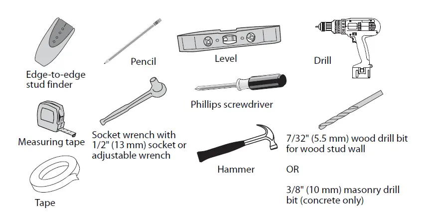
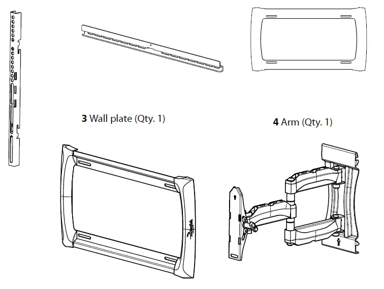
Package contents
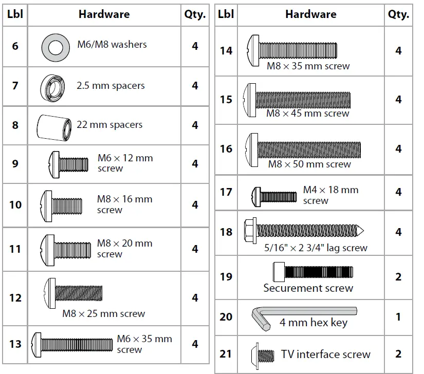
Make sure that you have all the hardware necessary to assemble your new TV wall mount:
- Vertical Brackets (Qty. 2)
- Horizontal brackets (Qty. 2)
- Wall plate (Qty. 1)
- Arm (Qty. 1)

TV Hardware
Concrete Installation Kit CMK1 (not included)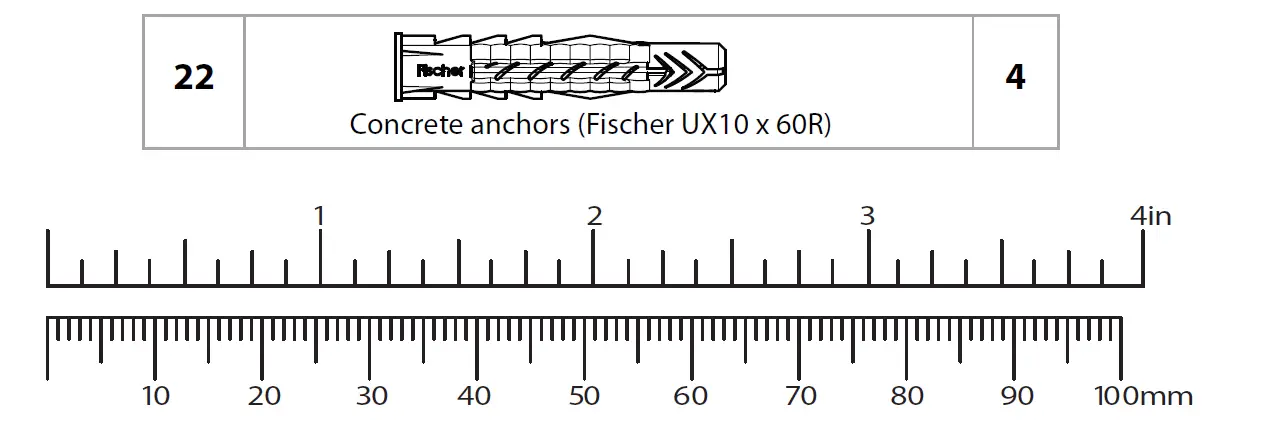
Contact customer service at 1-800-359-5520 to have these additional parts shipped directly to you.
Installation instructions
Step 1 – Determine whether your TV has a flat back or an irregular or obstructed back
- Carefully place your TV screen face-down on a cushioned, clean surface to protect the screen from damage and scratches.
- If your TV has a tabletop stand attached, remove the stand. See the documentation that came with your TV for instructions.
- Temporarily lay the vertical brackets (1) on the back of your TV.
- Align the screw holes in the vertical brackets with the mounting screw holes on your TV.
- Identify which type of back your TV may have:
- Flat back: The brackets lay flush against the back of your TV and do not block any jacks. You do not need spacers when assembling the wall mount.

- Obstructed back: The brackets block any of the jacks on the back of your TV. You will need spacers (7 or 8) when assembling the wall mount.

- Irregularly shaped back: There is a gap between the brackets and some part of the back of your TV. You will need spacers (7 or 8) when assembling the wall mount.

- Flat back: The brackets lay flush against the back of your TV and do not block any jacks. You do not need spacers when assembling the wall mount.
- Remove the vertical brackets.
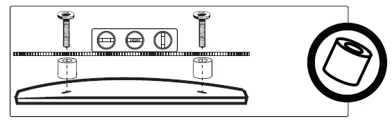
STEP 2 – Select screws, washers, and spacers
Select the hardware for your TV (screws, washers, and spacers). A limited number of TVs come with mounting hardware included. (If there are screws that came with the TV, they are almost always in the holes on the back of the TV.) If you don’t know the correct length of the mounting screws your TV requires, test various sizes by hand threading the screws. Select one of the following types of screws:
- M6 × 12 mm screws (9)
- M8 × 16 mm screws (10)
- M8 × 20 mm screws (11)
- M8 × 25 mm screws (12)
- M6×35mm screws 13
- M8×35mm screws 14
- ( M8×45mm screws 15
- ( M8×50mm screws 16
Use M6/M8 washers (6) for all screws.
For irregular or obstructed TV back, also use the 2.5 mm (7) or 22 mm spacers (8).
CAUTION:
To avoid potential personal injuries and property damage, make sure that there are adequate threads to secure the brackets to your TV. If you encounter resistance, stop immediately and contact customer service. Use the shortest screw and spacer combination to accommodate your TV. Using hardware that is too long may damage your TV. However, using a screw that is too short may cause your TV to fall from the mount.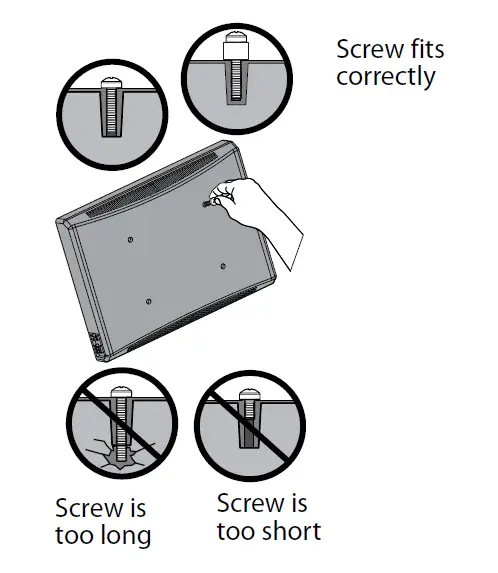
Remove the screws. For a flat-back TV, go to Attaching the vertical brackets to TVs with a flat back” on page 7. -OR- For an irregular or obstructed back, go to “STEP 3 – Option 2: Attaching the vertical brackets to TVs with irregular or obstructed backs” on page 8.
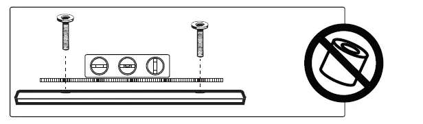
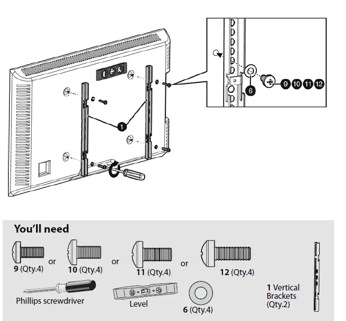
STEP 3 – Option 1: Attaching the vertical brackets to TVs with a flat back
- Align the holes you noted on the vertical brackets (1) with the screw holes on the back of your TV. Make sure the brackets are level.
- Place the washers (6) over the holes in the vertical brackets that align with the screw holes on the back of your TV, then insert the screws (9, 10, 11, or 12) through the washers.
- Tighten the screws until they are snug against the vertical brackets. Do not over-tighten.

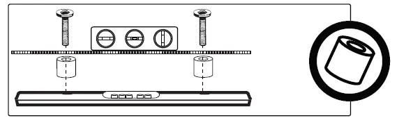
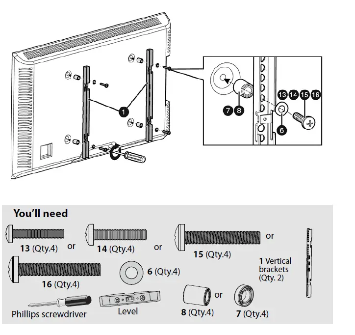
STEP 3 – Option 2: Attaching the vertical brackets to TVs
with irregular or obstructed backs
- Place the 2.5 mm (7) or 22 mm spacers (8) over the screw holes on the back of the TV.
- Align the vertical brackets (1) over the spacers (7 or 8), then place the washers (6) over the holes in the vertical brackets and insert the screws (13, 14, 15, or 16) through the washers, vertical brackets, and spacers. Make sure that the brackets are level.
- Tighten the screws until they are snug against the vertical brackets. Do not over-tighten.

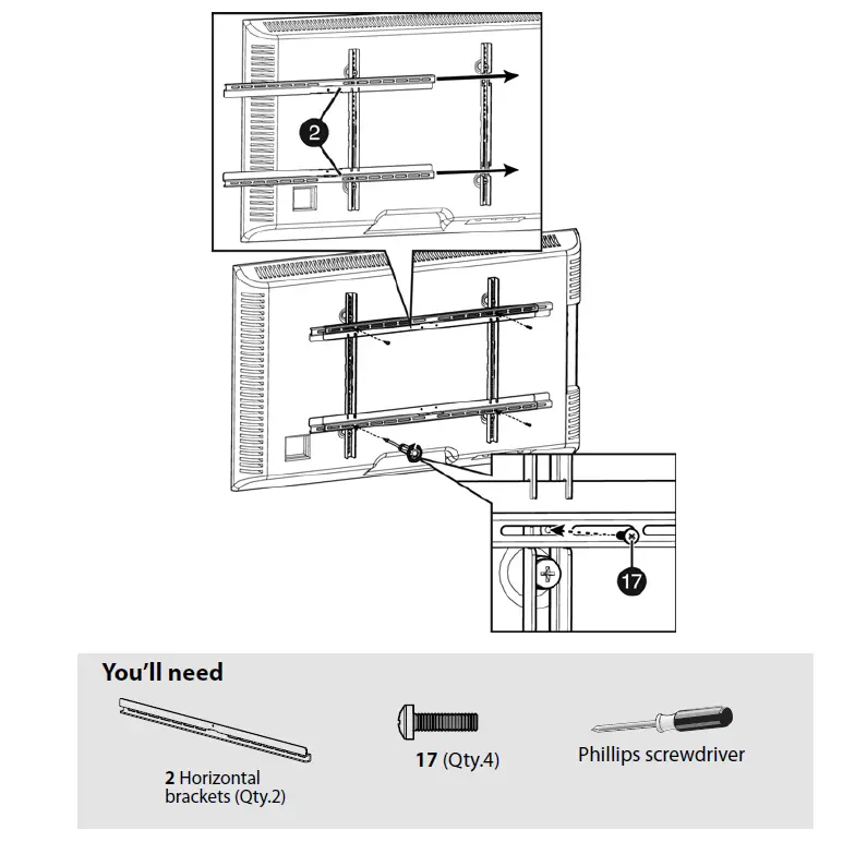
STEP 4 – Attaching the horizontal brackets
- Slide the horizontal brackets (2) through the slots in the vertical brackets (1), as shown below. Make sure that the brackets are centered.
- Secure the horizontal brackets (2) to the vertical brackets (1) with the M4 x 18 screws (17). Tighten the screws until they are snug against the horizontal brackets. Do not over-tighten.

STEP 5 – Determine the wall-mount location
- For more detailed information on determining where to drill your holes, visit our online height-finder at: http://mf1.bestbuy.selectionassistant.com/index.php/heightfinder
- Your TV should be high enough so your eyes are level with the middle of the screen. Normally, 40 to 60 inches from the ground.
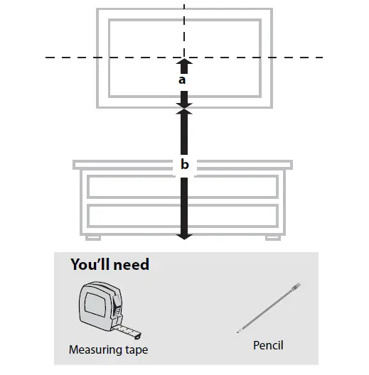
The center of your TV will match the center of the wall plate (3). Before you drill holes in the wall:
- Measure the distance from the bottom of your TV to the middle of the four mounting screw holes. This is measurement a.
- Measure the distance from the floor to where you want the bottom of the TV to be placed on the wall. Keep in mind that the bottom of the TV should be placed above any furniture (such as entertainment centers or TV stands). The TV should also be above items placed on top of the furniture (like a Blu-ray player or cable box). This is measurement b.
- Add a + b. The total measurement is the height where you want the center of the wall plate (3) to be on the wall.
- Use a pencil to mark this spot on the wall.

STEP 6 – Option 1: Installing on a wood stud wall
Note: Drywall covering the wall must not exceed 5/8″ (16 mm).
- Locate the stud. Verify the center of the stud with an edge-to-edge stud finder. 2 Make sure that the distance between the studs is 16 inches.
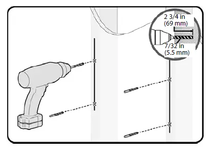
- Align the center of the wall plate template (5) at the height you determined in the previous step and make sure that it is level. Tape the wall plate template to the wall, then use a pencil to mark the four lag screw hole locations of the stud centers. Remove the wall plate template.

- Drill four pilot holes to a depth of 2 3/4 in. (69 mm) using a 7/32 in. (5.5 mm) diameter drill bit.

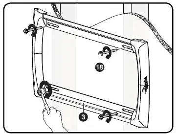
- Align the wall plate (3) with the pilot holes, insert the lag screws (18) through the holes in the wall plate assembly, then tighten the lag screws only until they are firm against the wall plate assembly.
CAUTION:
Avoid potential injuries or property damage! DO NOT over-tighten the lag screws (18).
STEP 6 – Option 2: Installing on a solid concrete or concrete block wall
CAUTION:
To prevent property damage or personal injury, never drill into the mortar between the blocks. Mount wall plate directly onto the concrete surface.
Note Minimum solid concrete thickness: 8 in (203 mm). Minimum concrete block size: 8 x 8 x 16 in. (203 x 203 x 406 mm).
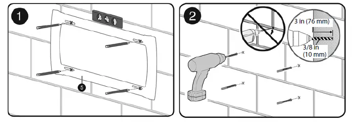
- Align the center of the wall plate template (5) at the height you determined in the previous step and make sure that it is level. Tape the wall plate template to the wall, then use a pencil to mark the four lag screw hole locations. Remove the wall plate template.
- Drill pilot holes to a depth of 3 in. (76 mm) using a 3/8 in. (10 mm) diameter masonry drill bit.

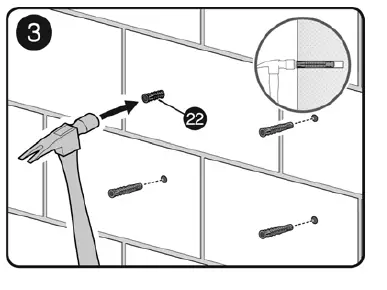
- Insert the concrete wall anchors (22) (refer to “Concrete Installation Kit CMK1 (not included)” on page 4) into the pilot holes and use a hammer to make sure that the anchors are flush with the concrete surface.

- Align the wall plate (3) with the anchors, insert the lag screws (18) through the holes in the wall plate assembly, then tighten the lag screws only until they are firm against the wall plate.
CAUTION:
Avoid potential injuries or property damage! DO NOT over-tighten the lag screws (18).
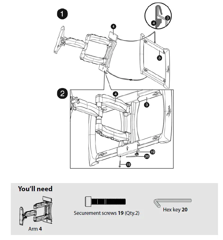
STEP 7 – Attach the arm to the wall plate
- Hang the earm4 onto the wall plate (3) by first hooking the top support, then lowering the bottom of the arm into place.
- Lock the earm4)to the wall plate (3) with the securement screws (19), using the hex key (20).
IMPORTANT:
These securement screws must be installed to secure the TV onto the wall plate assembly.
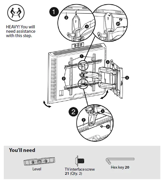
STEP 8 – Attach the TV to the arm
- To make it easier to attach your TV to the wall plate, position the arm (4) so the elbow is bent 90 degrees and pressed against the wall.
- Hang the TV onto the arm (4) by first hooking the top support, then lowering the bottom of the TV into place.
- Lock the TV to the arm (4) with the TV interface screws (21).

STEP 9 – Making adjustments and managing cables
- The following adjustments are available by loosening the tilt control knob.
NOTE:
Once your TV is in place, tighten the tilt tension knob to prevent unwanted movement.
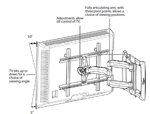
Manage cables by fully extending the arms to provide enough slack, then routing cables along the arms and inserting them into the channels on the arms, providing a clean look to your installation.
Removing the TV from the wall mount
- To remove your TV from the wall plate assembly, disconnect all cables, then reverse the procedures in Step 8.
IMPORTANT:
Your TV is heavy. You may need assistance with this step. For customer service, call: 1-800-620-2790 (U.S. and Canada) or www.rocketfishproducts.com
(800) 620-2790 (U.S. and Canada) ROCKETFISH is a trademark of Best Buy and its affiliated companies. Registered in some countries. Distributed by Best Buy Purchasing, LLC 7601 Penn Ave South, Richfield, MN 55423 U.S.A. ©2016 Best Buy. All rights reserved. Made in China


