![]() LED-AN
LED-AN
LED ANNUNCIATOR
Features
| Standby Current | 35 mA |
| Alarm Current | 75 mA |
| Ambient Operating Temp | 0°C-49°C (32°F-120°F) |
| Maximum Wire Length | 4000° |
| Maximum Annunciators | 31 |
| Size (H x W x D) | 5-7/8″x7″x1-1/2″ |
| Wire Gauge | 14 AWG-22 AWG |
Description
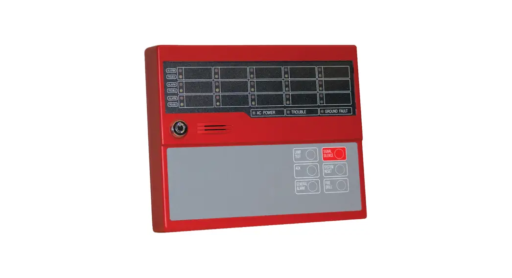
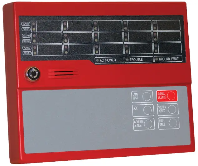
The LED-AN is a LED remote annunciator for the PFC-8060 and PFC-8500 addressable fire control panel. The LED-AN communicates using a RS-485 connection to the main panel providing common indication of Alarms, Supervisory, Trouble and other system status and control functions.
The LED-AN features 14 front panel L.E.D.s with LED’s for Power, Alarm, Supervisory, Trouble, and Silenced conditions. It can be mounted on a 2-gang electrical box or a standard 4″ sqaure electrical box. The keypad is only operable when a key-locked security switch is set to the enable position.
Installation
NOTICE
Install in accordance with installation manual # 5403556.
The LED-AN is connected to the PFC-8500 using a four wire RS-485 connection. The connection is power limited and supervised. Up to thirty-one (31) remote annunciators can be connected using Class B(Style 4) wiring.
Configuration Characteristics
- The RS-485 maimum wire length is 4000 feet (1219.2 meters)
- Maximum wiring resistance is less than 40 ohms
- Maximum capacitance between wiring is less than 0.4 micro F
LED-AN Class B Wiring Example
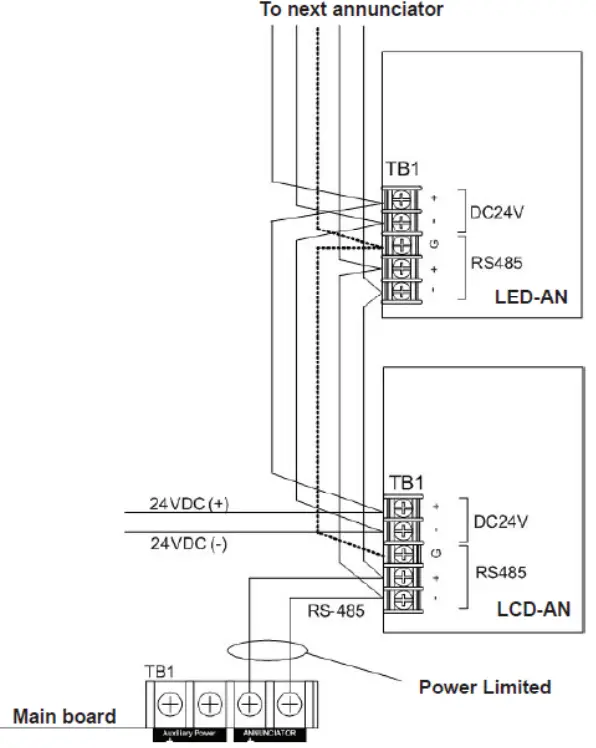
Notes
- JP of the farthest annunciator shall be shorted, and JP of other annunciators shall be open
- Any connection to ground of 10,000 ohms will be annunciatedas a ground fault
- Remote annunciators must be mounted on either a 2-gang or standard 4-inch square electrical box
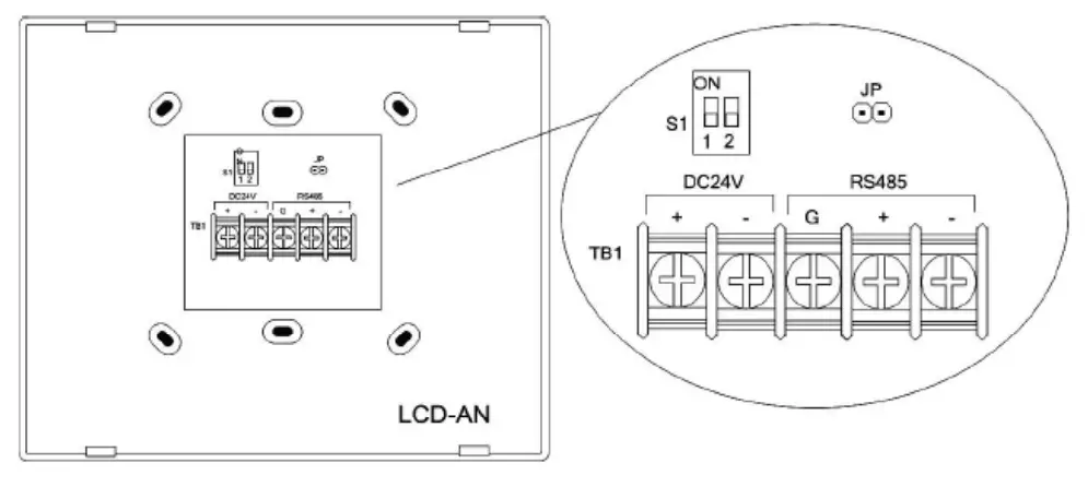
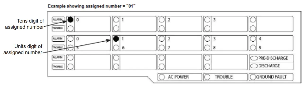
Address Settings
- Switch 1 of Dip Switch S1 set on, after that input 24 VDC to TB1.

- The LED-AN shows LED display as follows.

- The tens digit of the assigned number by LAMP TEST key / SIGNAL SILENCE key. After that, push ACK key.
- Set the units digit of the assigned number by LAMP TEST key / SIGNAL SILENCE key. After that, push ACK key.
- Switch 1 of Dip switch S1 set off, LED-AN will proceed to initializing.
![]()
MKT. #8830026 – REV B1
10/11
PRINTED IN USA
firealarmresources.com![]()


