aoni E93G Smart Battery Doorbell Camera User Guide
Welcome
Thank you for choosing our smart camera. Getting started is easy
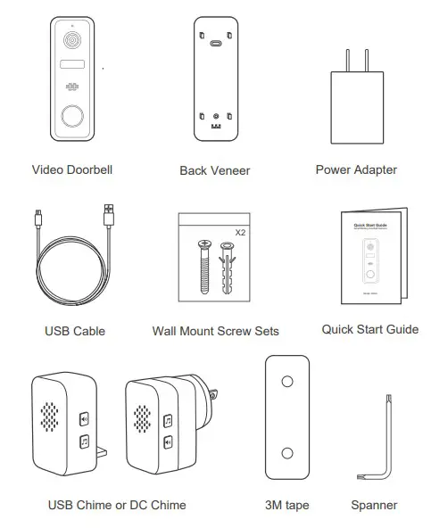
What’s Included
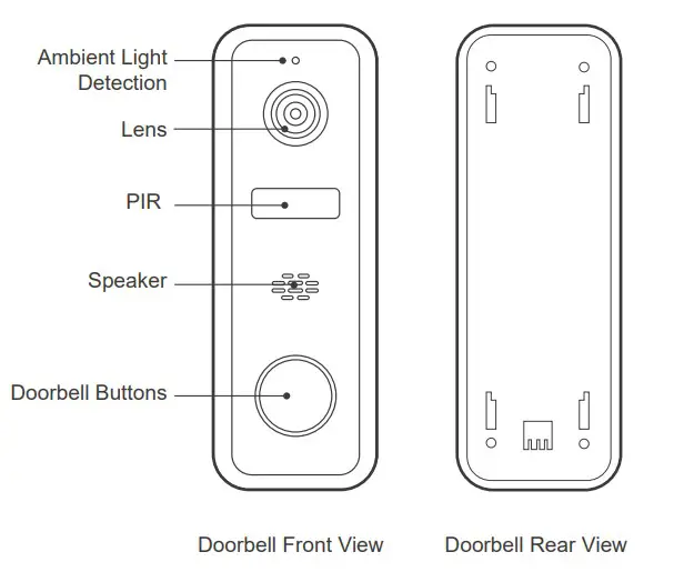
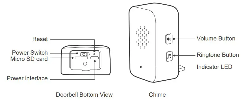
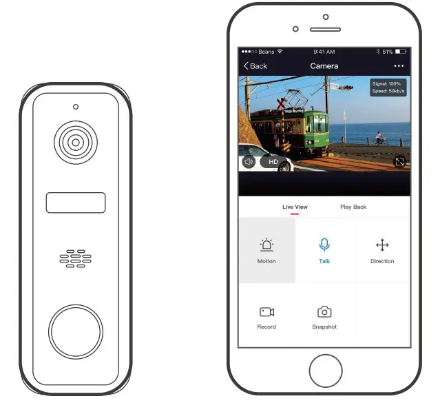
Product Details
Connection Preparation
Bring the doorbell and phone within 1 to 3 feet (30 to 100 centimeters) of the router.
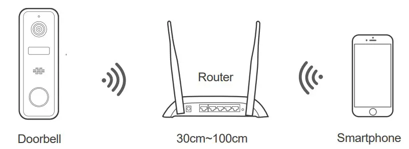
Note: Make sure smart phone is connected with your wireless router.
Please note the doorbell is only working under 2.4G Wi-Fi, not support 5G Wi-Fi.
Get the APP and Account
For the best experience, please download the “Tuya smart” APP to your smartphone from App Store or Google Play, or you can also scan the QR code below, the APP icon will be displayed after installed successfully.


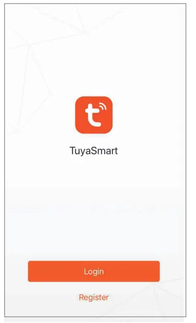
Launch the app from your smartphone and click the Sign Up button. Follow the on-screen instructions.
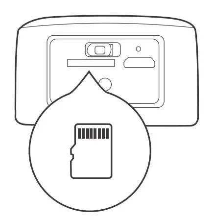
Insert the Micro SD card
Insert the Micro SD card gently on the side edge of doorbell.
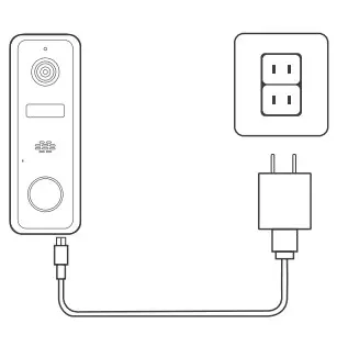
Connect the power to the doorbell
Connect the power to the doorbell by Micro USB Power Adapter.(DC5V/1.5A)
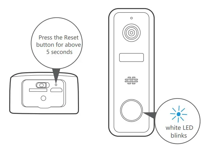
Set up your doorbel
- Press the Reset button for above 5 seconds, then release the button to reset the camera, then the LED light will blink in white slowly.
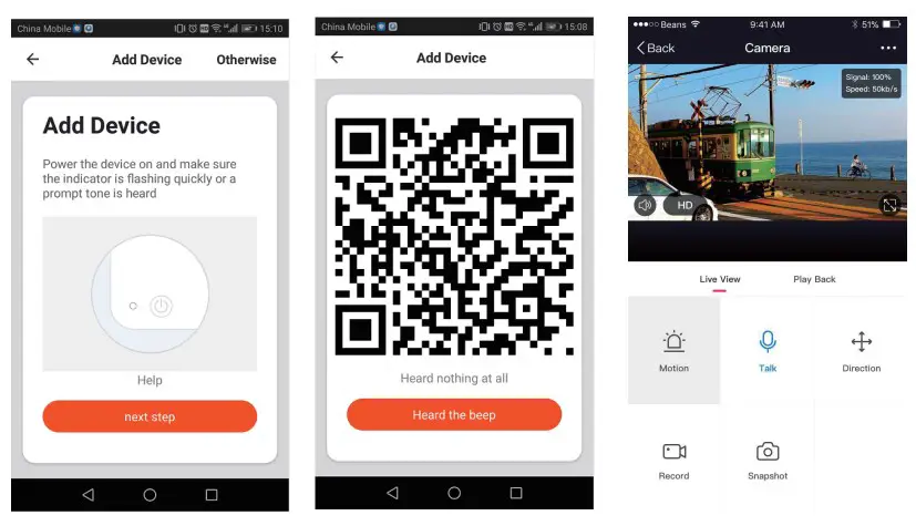
- Click “Add Device” or “+” on the right corner to add device; Then click” Security&Video Surveillance” to select ” Smart Doorbell” 5. Set up your doorbell
- Follow the App’s instructions and input the right wifi password; Point the QR code to the camera lens for 15-20cm ; Click”HEARD THE BEEP” when you heard “dingding”. After processing, it paired successfully


Pairing of doorbell and chime
- Press and keep the volume button of chime, until you hear the sound of “Ding Ding Ding Ding” from chime.
- Press the doorbell button, you can hear” Ding dong” too.
- Press the doorbell button again, the chime rings mean the paring is successful.
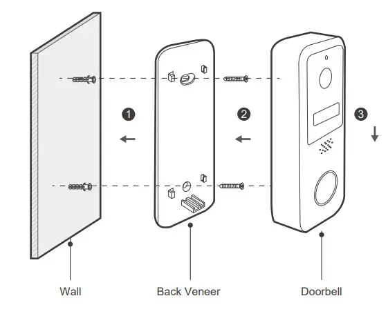
Schematic diagram of doorbell installation
- Hammer expansion bolt into wall body as per the hole position of locating sticke;
- Use a screw to fix the back plate;
- Put the doorbell downward to buckle it on the back plate to complete installation.

You’re done!
Congratulations! Your doorbell is set up and ready to go.
Appendix: Camera LED Guide
| NO. | LED Status | Camera Status |
| 1 | White LED on for 2 seconds | System starting up |
| 2 | White LED blinks slowly | Standby for configuration |
| 3 | White LED blinks quickly | Doorbell networking failure |
| 4 | White LED on for 2 seconds | Doorbell networking successful |
| 5 | White LED goes out | Doorbell sleeping normally |
| 6 | White LED breath flash | Doorbell wake up |
| 7 | White LED breath flash | Press the doorbell button |
| 8 | White LED blinks slowly | OTA upgrade |
| 9 | Green LED on | Doorbell charging |
| 10 | Green LED goes out | Doorbell charging complete |
| 11 | Green LED blinks quickly | Doorbell charging abnormally |
| 12 | White LED always on | Doorbell working abnormally |
FCC Statement
- This device complies with Part 15 of the FCC Rules. Operation is subject to the following two conditions: (1) This device may not cause harmful interference. (2) This device must accept any interference received, including interference that may cause undesired operation.
- Changes or modifications not expressly approved by the party responsible for compliance could void the user’s authority to operate the equipment.
Note:This equipment has been tested and found to comply with the limits for a class B digital device,pursuant to Part 15 of the FCC Rules. These limits are designed to provide reasonable protection against harmful interference in a residential installation.
This equipment generates uses and can radiate radio frequence energy and,if not installed and used in accordance with the instructions,may cause harmful interference to radio communications.However,there is no guarantee that interference will not occur in a particular installation.if this equipmemt does cause harmful interference to radio or television reception,which can be determined by turning the equipment off and on,the user is encouraged to try to correct the interference by one or more of the following measures:
- Reorient or relocate the receiving antenna.
- Increase the separation between the equipment and receiver.
- Connect the equipment into an autlet on a circuit different from that to which the receiver is connected.
- Consult the dealer or an experienced radio/TV technician for help.
This equipment should be installed and operated with a minumum distance of 20 cm between the radiator and your body.

All trademarks are used for reference purposes only.
Thanks again for choosing our smart camera! Makelife safe in your hands! Boost security mobility in your smartphone!


