![]()
30AMP PWM SOLAR
CONTROLLER
User Manual
GP-PWM-30-SQ
INSTALLATION OVERVIEW
INTRODUCTION
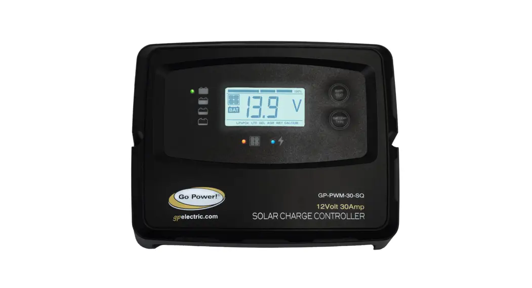
A Solar Controller (or Charge Controller / Regulator) is an essential component of your photovoltaic solar system. The Controller maintains the life of the battery by protecting it from overcharging. When your battery has reached a 100% state of charge, the Controller prevents overcharging by limiting the current flowing into the batteries from your solar array.
The GP-PWM-30-SQ is rated for a continuous solar current input of 30 amps, uses Pulse Width Modulation (PWM) technology, and a unique four-stage charging system that includes an optional equalize setting to charge and protect your battery bank.
SPECIFICATIONS
| DESCRIPTION | VALUE | |
| Rated solar panel amps for 10A/10AW Nominal System Voltage | 3 OA 15-22 VDC | Dimensions (H x W x D): 155 x 125 x 38 mm 6.10 x 4.92 x 1.50 in Weight: 151 grams / 5.34 oz Maximum Wire Gauge: #6 AWG Warranty: 1 year • PWM charging • 6 Battery charging profiles • 5 Stage charging • Monthly equalize option •Displays charging current, Battery voltage and battery state of charge • Reverse polarity protected • Temperature compensated • RoHS compliant • Accepts up to 30 Amps DC Input Current The total rated Maximum Power Current (Imp) of the PV input should not exceed 30 Amps |
| Max. solar cell array voltage (output has no load) | 25 VDC | |
| Lowest operating voltage (solar or battery side) | 8 VDC min | |
| Max voltage drop-solar panel to the battery | 0.25 VDC | |
| Min battery start charging voltage | 3 VDC | |
| Soft start charging voltage | 3-10 VDC (+/-0.2) | |
| Soft start charging current (50% PWM duty) | Up to 15 Amps | |
| Bulk charge voltage | 10-14.6 VDC (+/-0.2) | |
| Absorption charging voltage at 25°C | ||
| LTO type battery | 14.0 VDC (+1-0.2) | |
| GEL | 14.1 VDC (+/-0.2) | |
| AGM (Default) | 14.4 VDC (+1-0.2) | |
| LiFePO4 | 14.4 VDC (+/-0.2) | |
| WET | 14.7 VDC (+/-0.2) | |
| Calcium | 14.9 VDC (+1-0.2) | |
| Absorption transits to Equalizing or Float condition: | ||
| Charging current drops to | 14.9 Amps (+1-0.1) | |
| Or Absorption charging timer timed out | 4 hours | |
| Equalizing charging active | ||
| Only for WET or Calcium battery | 10 VDC (+/-0.2) | |
| Automatic equalizing charging periodical | 28 days | |
| Equalizing charging voltage at 25°C | 15.5 VDC (+1-0.2) | |
| Equalizing charging timer timed out | 2 hours | |
| Float charging voltage at 25°C | 13.6 VDC (+1-0.2) | |
| For LTO and LiFePO4 battery | 13.4/14.0 VDC (+1-0.2) | |
| For Gel, AGM, WET, and Calcium | 13.6 VDC (+1-0.2) | |
| Voltage control accuracy | +1-1% | |
| Battery temperature compensation coefficient | -24 mVI°C | |
INSTALLATION OVERVIEW
| Temperature compensation range | -20~+50 °C |
| Operating Temperature | – 20 to 50°C / -13 to 122°F |
| Over-temperature protection during charging | 65 °C |
| Storage temperature | – 40 to 85°C / -40 to 185°F |
| Transient over-voltage protection with TVs or varistor | |
| Power terminal max stranded wire size | #12 AWG stranded -3mm, |
| Mounting | Vertical wall mounting |
| Humidity | 99% N.0 |
| Net Weight | Approx. 0.25kg / 0.55Ib |
| Protection | BReverse polarity & short circuit, No reverse current from the battery to solar at night |
 | Disconnect all power sources | Electricity can be very dangerous. Installation should be performed only by a licensed electrician or qualified personnel. |
 | Battery and wiring safety | Observe all safety precautions of the battery manufacturer when handling or working around batteries. When charging, batteries produce hydrogen gas, which is highly explosive. |
 | Wiring connections | Ensure all connections are tight and secure. Loose connections may generate sparks and heat. Be sure to check connections one week after installation to ensure they are still tight. |
 | Work safely | Wear protective eyewear and appropriate clothing during installation. Use extreme caution when working with electricity and when handling and working around batteries. Use properly insulated tools only. |
 | Observe correct polarity at all times | Reverse polarity of the battery terminals will cause the controller to give a warning tone. The reverse connection of the array will not cause an alarm but the controller will not function. Failure to correct this fault could damage the controller. |
 | Do not exceed the GP-PWM30-SQ Amp current and max voltage ratings | The current rating of the solar system is the sum of the Maximum Power Current (Imp) of the solar PV strings in parallel. The resulting system Imp current is not to exceed 30A. The voltage of the array is the rated open-circuit voltage (Voc) of the PV array and is not to exceed 25V. If your solar system exceeds these ratings, contact your dealer for a suitable controller alternative. |
CHOOSING A LOCATION
The GP-PWM-30-SQ is designed to be mounted against a wall, out of the way but easily visible.
The GP-PWM-30-SQ should be:
- Mounted as close to the battery as possible
- Mounted on a vertical surface to optimize cooling of the unit
- Indoors, protected from the weather
Solar should connect directly to the controller. Positive and negative battery connections must connect directly from the controller to the batteries. Use of a positive or negative distribution bus is allowed between the controller and battery as long as it is properly sized, electrically safe, and adequate wire size is maintained. Note: In an RV, the most common controller location is above the refrigerator. The wire from the solar array most commonly enters the RV through the fridge vent on the roof.
INSTALLATION INSTRUCTIONS
1. Select wire type and gauge. If this GP-PWM-30-SQ was purchased as part of a Go Power! Solar Power Kit, appropriate wire type, gauge, and length is provided. Please continue to Section 5, “Operating Instructions.” If the GP-PWM-30-SQ was purchased separately, follow the instructions included here. Wire type is recommended to be a stranded aluminum UV resistant wire. Wire fatigue and the likelihood of a loose connection are greatly reduced in stranded wire compared to solid wire. Wire gauge should be able to sustain rated current as well as minimize voltage drop.
Suggested Minimum Wire Gauge
(Cable length 25 ft. max. from the solar array to battery bank)
| 80 Watt Solar Module | #12 Wire Gauge |
| 95 Watt Solar Module | #10 Wire Gauge |
| 170 Watt Solar Module | #10 Wire Gauge |
| 190 Watt Solar Module | #10 Wire Gauge |
For other applications, please refer to the standard wire guide.Identify the polarity (pos. and neg.) on the cable used for the battery and solar module. Use colored wires or mark the wire ends with tags. Although the GP-PWM-30-SQ is protected, a reverse polarity contact may damage the unit
2. Wiring the GP-PWM-30-SQ. Wire the GP-PWM-30-SQ according to the wiring schematic in Section 8. Run wires from the solar array and the batteries to the location of the GP-PWM-30-SQ. Keep the solar array covered with an opaque material until all wiring is completed. Torque all terminal screws to 16 inch-pounds (1.8N.m). Connect the battery wiring to the controller first and then connect the battery wiring to the battery
Use appropriate circuit protection on any conductor attached to a battery.
With battery power attached, the controller should power up and display information. Connect the solar wiring to the controller and remove the opaque material from the solar array. The negative solar array and battery wiring must be connected directly to the controller for proper operation. Do not connect the negative solar array or negative battery controller wiring to the chassis of the vehicle.
3. Mounting the GP-PWM-30-SQ. Mount the GP-PWM-30-SQ to the wall using the included two mounting screws. After 30 days of operation, re-torque all terminal screws to ensure the wires are properly secured to the controller. Congratulations, your GPPWM-30-SQ should now be operational. If the battery power is low and the solar array is producing power, your battery should begin to charge.
You must set the battery type on the GP-PWM-30-SQ before you begin to use the controller.
POWER UP
Please check your battery manufacturer’s specifications to select the correct battery type. The unit provides 6 battery types for selections: LTO, Gel, AGM, LiFePO4, WET (conventional lead-acid), and Calcium.
SETTING THE BATTERY CHARGING PROFILE
Press the BATTERY TYPE button and hold for 3 seconds to go into your battery type selection mode, the battery types you select will be shown on the LCD meter. The controller will automatically memorize your battery type setting.Incorrect battery type settings may damage your battery.
When the controller powers on, the unit will run self-test mode and automatically show below items on LCD before going into the charging process. Refer to the Battery Charge Profile Chart for details on each profile.
 | Self-test starts, digital meter segments test |  | Software version test |
 | Rated voltage |  | Current test |
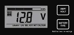
After going into the charging process, the LCD displays the charging states as below. Press VOLT / AMP button in sequence, the LCD will display in turn with Battery Voltage, Charging Current, Charged capacity (Amp-hour), and Battery Temperature (if external temperature sensor connected).
BATTERY CHARGING PROFILE CHART
| The 6 LED’s indicate the charging status and the battery condition |  |  |  |  |  |  |
| RED | BLUE | GREEN | GREEN | YELLOW | RED | |
| Solar Power Present- No battery connected | ON | OFF | OFF | OFF | OFF | Flash |
| Soft charging | ON | Flash | OFF | OFF | OFF | ON |
| Bulk charging (Vb < 11.5V) | ON | ON | OFF | OFF | OFF | ON |
| Bulk charging (11.5V < Vb < 12.5V) | ON | ON | OFF | OFF | ON | OFF |
| Bulk charging (Vb > 12.5V) | ON | ON | OFF | ON | OFF | OFF |
OPERATING INSTRUCTIONS
| Absorption charging | ON | ON | OFF | ON | OFF | OFF |
| Float charging | ON | OFF | ON | OFF | OFF | OFF |
| Solar panel weak | Flash | OFF | OFF | Subject to battery voltage | ||
| At night no charge | OFF | OFF | OFF | Subject to battery voltage | ||
WET CELL BATTERY CHARGING ALGORITHM
Auto Equalize: The GP-PWM-30-SQ has an automatic equalize feature that will charge and recondition your batteries once a month at a higher voltage to ensure that any excess sulfation is removed. This feature is recommended for Flooded batteries only. Check with your battery manufacturer. This feature is only available for wet cell or flooded
batteries
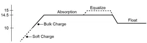
Soft Charge- When batteries suffer an over-discharge, the controller will softly ramp the battery voltage up to 10V.
Bulk Charge-Maximum current charging until batteries rise to the Absorption level
Absorption Charge-Constant voltage charging and battery is over 85%
Equalization Charge*– Only for WET battery (Flooded lead acid) or Calcium battery type, when the battery is deeply drained below 10V, it will automatically run this stage to bring the internal cells to an equal state and fully complement the loss of capacity. (Gel and AGM battery does not run Equalization charge)
Float Charge-Battery is fully charged and maintained at a safe level. The battery is fully charged and maintained at a safe level. A fully charged battery has a voltage of more than 13.6 Volts. A fully charged LiFePO4 battery has a voltage level of 14.6V. LTO has a voltage level of 13.4V.
FAULT CODES
| SOLAR PANEL ABNORMAL MODE | LCD DISPLAY | LED INDICATION | LCD BACKLIGHT |
| Solar panel weak | FLASH | ON | |
| Solar panel reverse connection |  | FLASH | FLASH |
| Solar panel overvoltage (> 26.5V) |  | FLASH | FLASH |
| BATTERY ABNORMAL MODE | LCD DISPLAY | LED INDICATION | LCD BACKLIGHT | ||
| Battery disconnected or less than 3.0V |  | FLASH | FLASH | ||
| Battery reverse connection |  | FLASH | FLASH | ||
| Battery over-voltage than > 17.5V |  | FLASH |  FLASH FLASH | FLASH | FLASH |
| Battery temperature over 65°C |  | FLASH | FLASH | FLASH | FLASH |
| SOLAR CONTROLLER ABNORMAL MODE | LCD DISPLAY | LED INDICATION | LCD BACKLIGHT |
| The controller over temp. protection |  | FLASH |
Lithium Battery Reset
This solar controller has a lithium reset feature that allows a BMS-protected over-discharged battery to be manually recovered without having to disconnect the battery. In order for this to work, there must be solar power available to power the solar controller. The reset is performed by holding both the VOLT/AMP button and the BATTERY TYPE button for 1S.
FREQUENTLY ASKED QUESTIONS (FAQs)
Visit gpelectric.com to read the Frequently Asked Questions section on our website.
TROUBLESHOOTING
PROBLEMS WITH DISPLAY
Display Reading: Blank
Time of Day: Daytime/Nighttime
Possible Causes:
Battery or fuse connection and/or solar array connection (Daytime only) or battery or fuse connection (Nighttime only).
How to tell:
- Check the voltage at the controller battery terminals with a voltmeter and compare it with a voltage reading at the battery terminals.
- If there is no voltage reading at the controller battery terminals, the problem is in the wiring between the battery and the controller.
If the battery voltage is lower than 6 volts the controller will not function. - For the solar array, repeat steps 1 and 2 substituting all battery terminals with solar array terminals.
Remedy:
Check all connections from the controller to the battery including checking for correct wire polarity. Check that all connections are clean, tight, and secure. Ensure the battery voltage is above 6 volts.
PROBLEMS WITH VOLTAGE
OPERATING INSTRUCTIONS
Voltage Reading: Inaccurate
Time of Day: Daytime/Nighttime
Possible Causes:
Excessive voltage drops from batteries to controller due to loose connections, small wire gauge, or both.
How to tell:
- Check the voltage at the controller battery terminals with a voltmeter and compare it with the voltage reading at the battery terminals.
- If there is a voltage discrepancy of more than 0.5 V, there is an excessive voltage drop.
Remedy:
Check all connections from the controller to the battery including checking for correct wire polarity. Check that all connections are clean, tight, and secure. Shorten the distance from the controller to the battery or obtain a larger gauge wire. It is also possible to double up the existing gauge wire (i.e. two wire runs) to simulate a larger gauge wire.
PROBLEMS WITH CURRENT
Current Reading: 0 A
Time of Day: Daytime, clear sunny skies
Possible Cause:
Current is being limited below 1 Amp as per normal operation or poor connection between solar array and controller.
How to tell:
- The State of Charge (SOC) screen is close to 100% and the Sun and Battery icons are present with an arrow between them.
- With the solar array in sunlight, check the voltage at the controller solar array terminals with a voltmeter.
- If there is no reading at the controller solar array terminals, the problem is somewhere in the wiring from the solar array to the
controller.
Remedy:
Check all connections from the controller to the array including checking for correct wire polarity. Check that all connections are clean, tight, and secure. Continue with the solutions below for additional help on low current readings.
Current Reading: Less than expected
Time of Day: Daytime, clear sunny skies
Possible Causes:
- Current is being limited below 1 Amp as per normal operation.
- Incorrect series/parallel configuration and/or wiring connections and/or wire gauge.
- Dirty or shaded module or lack of sun.
- The blown diode in the solar module is when two or more modules are connected in parallel.
How to tell:
- The battery State of Charge screen is close to 100% and the Sun and Battery icons is present with an arrow in between.
- Check that the modules and batteries are configured correctly. Check all wiring connections.
- Modules look dirty, the overhead object is shading modules or it is an overcast day in which a shadow cannot be cast.
Avoid any shading no matter how small. An object as small as a broomstick held across the solar module may cause the power output to be reduced. Overcast days may also cut the power output of the module - Disconnect one or both array wires from the controller. Take a voltage reading between the positive and negative array wire. A single 12-volt module should have an open circuit voltage between 17 and 22 volts. If you have more than one solar module, you will need to conduct this test between the positive and negative terminals of each module junction box with either the positive or the negative wires disconnected from the terminal.
Remedy:
- Reconnect in the correct configuration. Tighten all connections. Check wire gauge and length of wire run. Refer to Suggested Minimum Wire Gauge in Section 4.
- Clean modules, clear obstruction or wait for conditions to clear.
- If the open-circuit voltage of a non-connected 12-volt module is lower than the manufacturer’s specifications, the module may be faulty. Check for blown diodes in the solar module junction box, which may be shorting the power output of the module.
WIRING DIAGRAM
The GP-PWM-30-SQ is based on a 30 amp max input from the solar modules. Use the wiring diagram to connect your battery to the battery terminals on the solar controller. First, connect the battery to the controller and then connect the solar panel to the controller. The controller will not work unless there is a battery connected to the battery terminals.
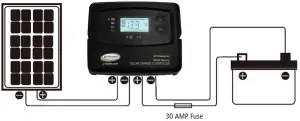
Note: The fuse or breaker used should be no larger than 30 amps.
Solar Panel +
Solar Panel –
Battery +
Battery –
WARRANTY
Go Power! warrants the GP-PWM-30-SQ for a period of one (1) year from the date of shipment from its factory. This warranty is valid against defects in materials and workmanship for the one (5) year warranty period. It is not valid against defects resulting from, but not limited to:
- Misuse and/or abuse, neglect, or accident
- Exceeding the unit’s design limits
- Improper installation, including, but not limited to, improper environmental protection and improper hook-up
- Acts of God, including lightning, floods, earthquakes, fire, and high winds
- Damage in handling, including damage encountered during shipment
This warranty shall be considered void if the warranted product is in any way opened or altered. The warranty will be void if any eyelet, rivets, or other fasteners used to seal the unit are removed or altered, or if the unit’s serial number is in any way removed, altered, replaced, defaced, or rendered illegible.
REPAIR AND RETURN INFORMATION
Visit www.gpelectric.com to read the “frequently asked questions” section of our website to troubleshoot the problem. If trouble persists:
- Fill out our online Contact Us form or Live Chat with us
- Email [email protected]
- Return defective product to the place of purchase
![]()
© 2021 Go Power!
Worldwide Technical Support and Product Information gpelectric.com
Go Power! | Dometic
201-710 Redbrick Street Victoria, BC, V8T 5J3
Tel: 1.866.247.6527
GP_MAN_GP-PWM-30-SQ


